

Page 1
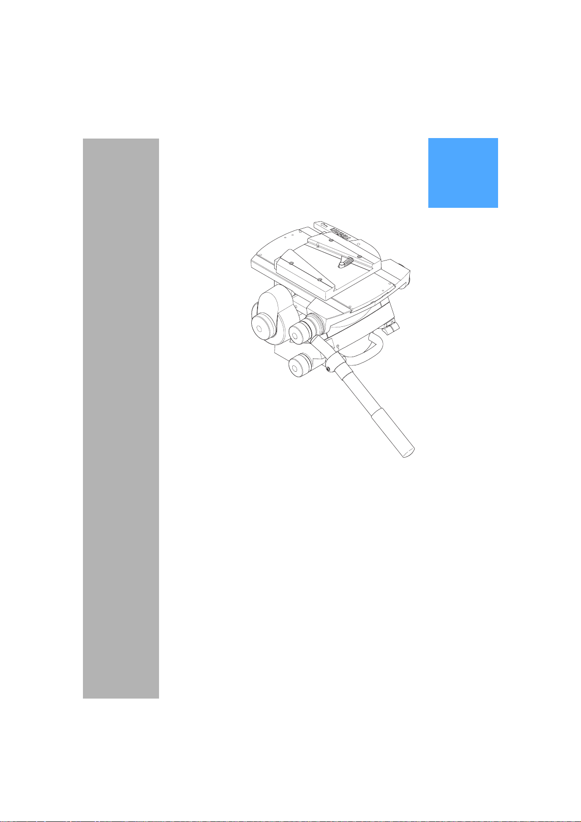
Vector 700/700H
Pan & Tilt Head
Vinten
Operators Guide
Camera Control Solutions
Page 2

Vector 700/700H
Pan and Tilt Head
Publication Part No. 3448-8 Issue 2
Copyright © Vinten Broadcast Limited 1997
All rights reserved throughout the world. No part of this document may be stored in a retrieval system, transmitted, copied
or reproduced in any way including, but not limited to, photocopy, photograph, magnetic or other record without the prior
agreement and permission in writing of
Vinten Broadcast Limited.
Vinten, Vector and Quickfix are registered trademarks of Vinten Broadcast Limited.
Page 3

Safety - Read This First
Warning Symbols in this Operators Guide
Where there is a risk of personal injury, injury to others, or damage to the pan
and tilt head or associated equipment, comments appear, highlighted by the
word WARNING! and supported by the warning triangle symbol.
Technical data
Maximum payload 70 kg (154 lb)
Payload Centre of Gravity height range
Vector 700 80 mm (3 in.) to 200 mm (8 in.)
Vector 700H 80 mm (3 in.) to 250 mm (10 in.)
Weight (complete with pan bar and wedge adaptor)
Vector 700 18.85 kg (41.5 lb)
Vector 700H 19.15 kg (42.1 lb)
Overall dimensions
Height (flat base with wedge adaptor )
Minimum balance setting 255 mm (10.0 in.)
Maximum balance setting 355 mm (14.0 in.)
Length (without pan bar) 355 mm (14.0 in.)
Width (without pan bar) 350 mm (13.8 in.)
Width (with two pan bars) 445 mm (17.5 in.)
Tilt range
Vector 700 ±60°
Vector 700H ±52°
Pan range 360°
3
Page 4

Further information
For further information or advice re garding this pan and tilt h ead, please contact Vinten Broa dcast
Limited, your local Vinten distributor or visit our website.
For details on maintenance and spare pa rts, please refer to the Vector 700/700H Pan and Tilt
Head (Grey) Maintenance Manual and Illust rate d Parts List (Pub licat ion Part No. 3 354-9) o r Vector 700/700H Pan and Tilt Head (Black) Maintenance Manual an d Illustrated Parts List (Publication Part No. 3458-9), obtainable from Vinten Broadcast Limited or your local Vinten distributor.
For information on-line, visit our website at
www.vinten.com.
4
Page 5

Contents
Page
Safety - Read This First . . . . . . . . . . . . . . . . . . . . . . . . . . . . . . . . . . . . . . . . . . . . . . . . . . . . . . 3
Technical data . . . . . . . . . . . . . . . . . . . . . . . . . . . . . . . . . . . . . . . . . . . . . . . . . . . . . . . . . . . . . . 3
Further information. . . . . . . . . . . . . . . . . . . . . . . . . . . . . . . . . . . . . . . . . . . . . . . . . . . . . . . . . . 4
Introduction
Operation
Unpacking . . . . . . . . . . . . . . . . . . . . . . . . . . . . . . . . . . . . . . . . . . . . . . . . . . . . . . . . . . . . . . . 9
Mounting the head. . . . . . . . . . . . . . . . . . . . . . . . . . . . . . . . . . . . . . . . . . . . . . . . . . . . . . . . . 9
Pan bars. . . . . . . . . . . . . . . . . . . . . . . . . . . . . . . . . . . . . . . . . . . . . . . . . . . . . . . . . . . . . . . . 10
Fitting a camera. . . . . . . . . . . . . . . . . . . . . . . . . . . . . . . . . . . . . . . . . . . . . . . . . . . . . . . . . . 10
Balancing the head . . . . . . . . . . . . . . . . . . . . . . . . . . . . . . . . . . . . . . . . . . . . . . . . . . . . . . . 11
Locking the platform . . . . . . . . . . . . . . . . . . . . . . . . . . . . . . . . . . . . . . . . . . . . . . . . . . . . . . 12
Pan and tilt brakes. . . . . . . . . . . . . . . . . . . . . . . . . . . . . . . . . . . . . . . . . . . . . . . . . . . . . . . . 12
Pan and tilt drag. . . . . . . . . . . . . . . . . . . . . . . . . . . . . . . . . . . . . . . . . . . . . . . . . . . . . . . . . . 12
Servicing
General . . . . . . . . . . . . . . . . . . . . . . . . . . . . . . . . . . . . . . . . . . . . . . . . . . . . . . . . . . . . . . . . 13
Cleaning. . . . . . . . . . . . . . . . . . . . . . . . . . . . . . . . . . . . . . . . . . . . . . . . . . . . . . . . . . . . . . . . 13
Cleaning balance mechanism tracks . . . . . . . . . . . . . . . . . . . . . . . . . . . . . . . . . . . . . . . 13
Routine maintenance. . . . . . . . . . . . . . . . . . . . . . . . . . . . . . . . . . . . . . . . . . . . . . . . . . . . . . 16
Level bubble illumination unit battery replacement. . . . . . . . . . . . . . . . . . . . . . . . . . . . . 16
Adjustments. . . . . . . . . . . . . . . . . . . . . . . . . . . . . . . . . . . . . . . . . . . . . . . . . . . . . . . . . . . . . 17
Platform slide clamp adjustment. . . . . . . . . . . . . . . . . . . . . . . . . . . . . . . . . . . . . . . . . . . 17
Repositioning the wedge adaptor. . . . . . . . . . . . . . . . . . . . . . . . . . . . . . . . . . . . . . . . . . 18
Pan and tilt brake adjustment . . . . . . . . . . . . . . . . . . . . . . . . . . . . . . . . . . . . . . . . . . . . . 19
Parts List . . . . . . . . . . . . . . . . . . . . . . . . . . . . . . . . . . . . . . . . . . . . . . . . . . . . . . . . . . . . . . . . . 21
Associated publications
Vector 700/700H Pan and Tilt Head (Grey)
Maintenance Manual
Publication Part No. 3448-9
Vector 700/700H Pan and Tilt Head (Black)
Maintenance Manual
Publication Part No. 3458-9
5
Page 6
(1)
(2)
(3)
(11)
(10)
(9)
(8)
(7)
(4)
(5)
(6)
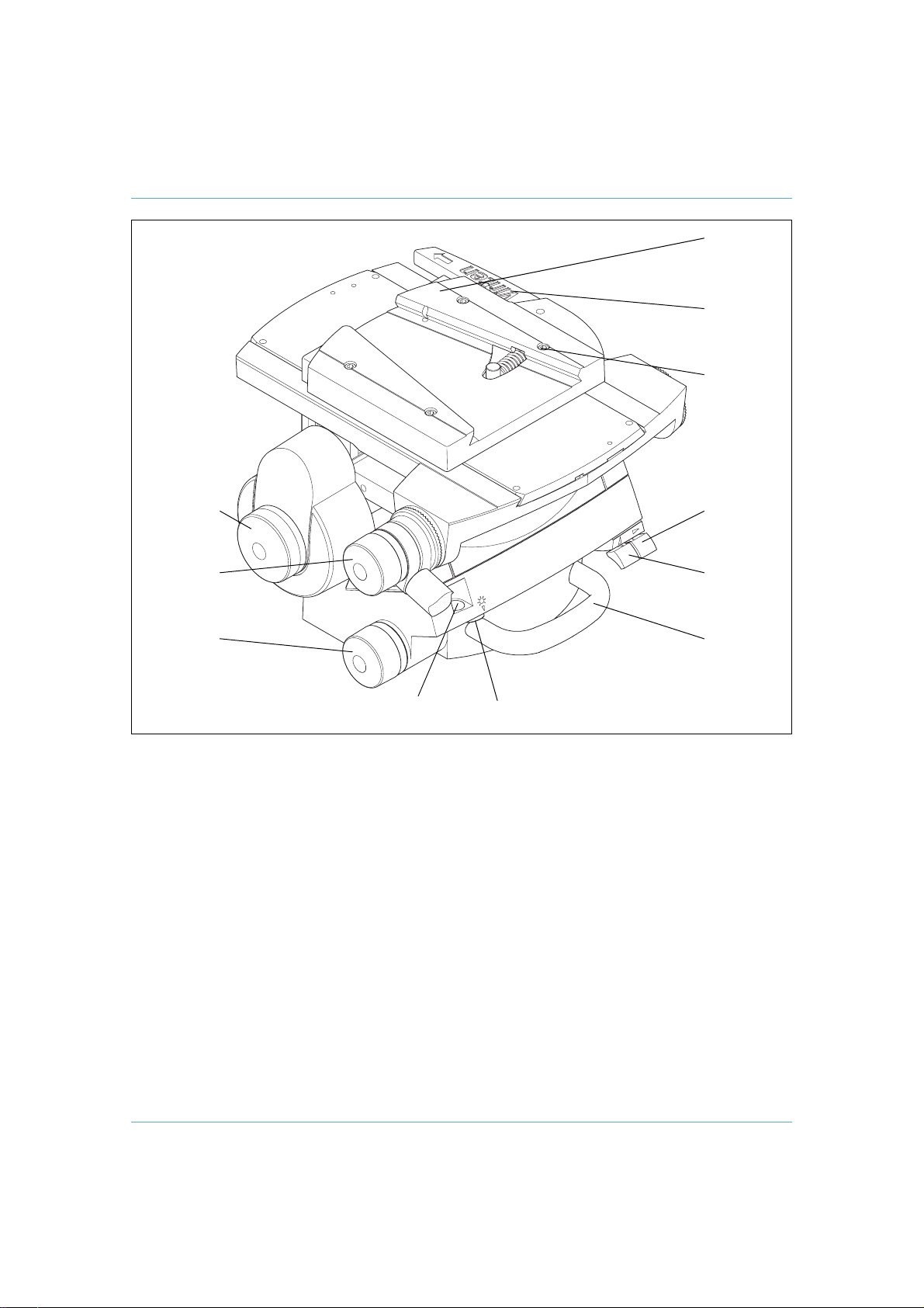
Vector 700/700H Pan and Tilt Head (Left-Hand Side)
(1) Wedge adaptor
(2) Wedge adaptor operating lever
(3) Wedge adaptor screw
(4) Pan brake lever
(5) Tilt brake lever
(6) Carrying handle
(7) Level bubble illumination switch
(8) Level bubble
(9) Pan drag adjustment knob
(10) Pan bar clamp
(11) Tilt drag adjustment knob
6
Page 7
(18)
(12)(17)
(13)(16)
(14)(15)
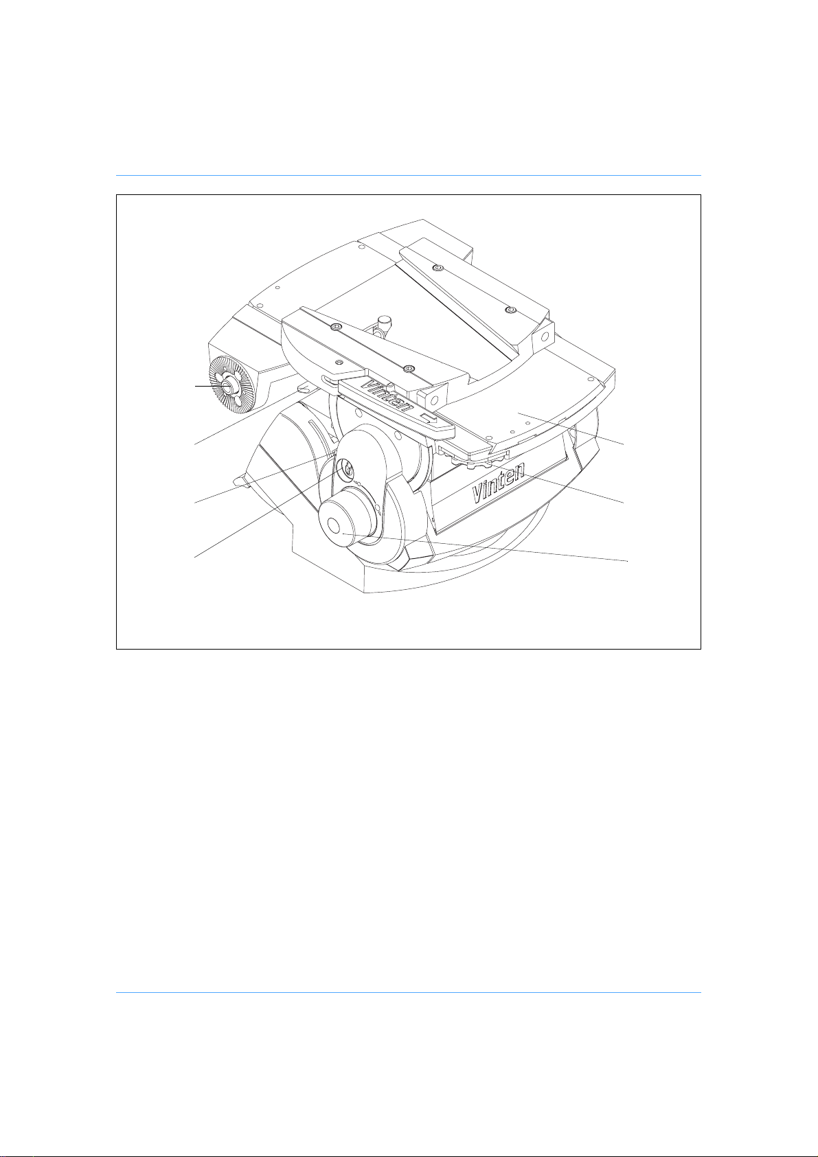
Vector 700/700H Pan and Tilt Head (Right-Hand Side)
(12) Sliding plate
(13) Sliding plate adjustment knob
(14) Balance adjustment knob
(15) Centre lock plunger
(16) Centre lock release lever
(17) Sliding plate clamp
(18) Pan bar mounting
7
Page 8

Introduction
The Vector 700/700H pan and tilt head embodies a unique lin kage counterbalancing mechanism,
thin film (TF) drag assemblies for pan and tilt motions and an adjustable camera mounting plate.
The balance system is easily adjusted by a knob (14) on the right-hand side of the head . The balance adjustment control compensates for di ffering platform load C of G heights by varyin g the mechanical advantage of a bell-crank in the counterbalance mechanism.
Both the pan and tilt mechanisms incorporate TF drag systems to ensure smooth movement of
the camera about these axes and are fitted with control knobs (9)(11) to adjust the drag setting.
The drag controls are mounted on the left-hand side of the head. The whip-pan facility is unaffected by the pan drag setting.
Friction brakes on each axis allow the head to be locked at any chosen position. The operating
levers for both brakes (4)(5) are fitted at t he right-hand rear of the hea d. A tilt axis centre lock (15)
is provided on the right-hand side of the head to secure the platform in the horizontal posit ion during transport or load changing.
A level bubble (8) is fitted to the rear of the head and is provided with a time-delay illumination
unit, operated by a switch (7). The battery for the illumination unit is contained in the base.
Pan bar mounting points (18) are located at the rear of the head, on either side of the camera
mounting platform. A telescopic pan bar is supplied and is attached using a pan bar clamp (10),
with angular adjustment available on the mo u nt serr at ion s. A seco n d pa n ba r ma y be fitte d, and
fixed and short pan bars are available as optional extras.
The camera is attached to the head by means of a wedge adaptor (1).
8
Page 9

Operation
Unpacking
The head is supplied with one pan bar and a battery (fitted) for the level bubble illumination unit.
The flat base version is supplied with four moun ting bolts, four washer s and a spanner. The Mitch-
ell fixing version is supplied with a lightweight Mitchell adaptor.
A second telescopic pan bar or short pan bar for use with a zoom or focus controller are optio nal.
Ensure that all items are unpacked prior to disposal of the packing materials.
After unpacking ensure that:
The centre lock (15) is engaged (See Locking the platform). Always engage the centre
lock before lifting or carrying the head. Lift the head by the base and/or the carrying handle,
not the platform.
The pan and tilt brakes (4)(5) are on (See Pan and tilt brakes).
Mounting the head
NOTE: When mounted on Vinten ‘Hawk’ or ‘Teal’ pedestals, clearance between the
head and the pedestal weight tray prevents the use of 5.5 lb (1.6 kg) and 1.0 lb
(0.47 kg) trim weights. Use alternati ve weights or fit the adaptor plate kit (Part
No. 3354-900SP) between the head and pedestal.
Flat base
WARNING! Before installing the head, hold a fixing bolt in position and
check that the threaded end does not project more than 12 mm
(1/2 in.) above the mounting face.
The head is mounted on a tripod, pedestal or su ita ble firm sur fa ce using t he fou r f ixing bolts an d
washers. Tighten the bolts with the spanner provided.
After mounting the head, use t he level bubble (8) to set it level. The level bubble may be illuminated by pressing the switch (7). The light will go out after approximately 15 seconds.
Mitchell-type fixing
Remove the clamp knob and washer. Position the head on the tripod or pedestal, ensuring that
the spigot is seated and the key is engaged in the slot. Re fit the clamp washer and knob a nd tighten securely.
After mounting the head, use t he level bubble (8) to set it level. The level bubble may be illuminated by pressing the switch (7). The light will go out after approximately 15 seconds.
9
Page 10

Pan bars
Fit the pan bars to the head and adjust the position of each o ne bef or e ti gh tenin g t he cla mp (10)
on the mounting (18). Adjust the length of the telescopic pan bars.
Fitting a camera
WARNING! Do not rely on the tilt brake whe n c h ang ing t he payload. Always
To fit a camera, proceed as follows:
Lower the mounting to a convenient working height.
If not already fitted, install t he wedge adap tor (1) in the middle position on the sliding plate
(12) (See Servicing).
Attach the wedge to the camera/lens.
Ensure that the centre lock (15) is engaged (See Locking the platform).
Slide the wedge adaptor operating lever (2) forward (parallel to the wedge) about 6 mm
(1/4 in.) against spring tension. Pull the operating lever out, aw ay fr om the bod y of the
wedge adaptor, as far as it will go.
Insert the camera wedge into the wedge adaptor an d push it forward into full engage ment.
Push in the operating lever (1) until it lies parallel with the wedge adaptor body. During this
operation resistance of the spring-loaded over-centre mechanism will be felt. As the lever
reaches the end of its travel it will slide back (parallel to the wedge) to the locked position.
Confirm that the lever is in the locked position. This is indicated by coloured bands above
the lever. When the green band only is visible, the lever is locked. If any of the red ban d can
be seen, the lever is not locked.
Install the remainder of the payload (lens, zoom and focus controls, viewfinder, prompter
etc).
engage the centre lock.
Ensure that the weight and C of G height of the total payload is
within the range for which the head is designed
Vector 700 - up to 70 kg (150 lb) with C of G height from 80 mm
(3 in) to 200 mm (8 in).
Vector 700H - u p to 70 kg (150 lb) with C of G height from 80 mm
(3 in) to 250 mm (10 in).
10
Page 11

Balancing the head
NOTE: It is important that the pan bar(s) and all camera accessories (lens, zoom and
focus controls, vie wfinder, prompter etc.) are fitted in their operational position
before balancing the head. Any equipment fitted or adjusted later will
unbalance the head.
Balancing the head consists of positioning the payload fo re and aft on the head so that it s C of G
is immediately above the platform pivot, then com p en sa tin g fo r the pa yloa d C of G heig ht us ing
the balance adjustment knob.
Position the payload fore and aft as follows:
Ensure that the centre lock is engaged (See Locking the platform) and that the camera
and all accessories are fitted.
Turn the tilt drag adjustment knob (11) to its minimum setting.
WARNI NG! If the balance control is se t to minimum, a heavy out-of-balance
payload will cause the platform to tip violently when the centre
lock is disengaged. Increase the C of G height setting (see
below) prior to balancing a heavy payload.
Holding the pan bar to steady the platform, disengage the centre lock (See Locking the
platform).
Release the sliding plate clamp (17) and turn the sliding plate adjustment knob (13) to move
the sliding plate fore and aft to achieve horizontal bala nce. The horizontal balance is correct
when no perceptible tilting force can be felt on t he pan bar with the platform leve l. Apply the
sliding plate clamp (17).
If there is insufficient movement in the sliding plate to achieve balance, reposition the
wedge adaptor (See Servicing), refit the load and repeat the horizontal balancing proce-
dure.
When fore and aft balance has been achieved, carry ou t the payload C of G height adjustment as
follows:
Using the pan bar, tilt the platform forward and backward. When corre ctly balanced, t here
should be no perceptible tilting force on the pan bar at a ny angle of tilt and th e head should
remain in any tilt position to which it is set.
If the head tends to fall away when the platform is tilted, push in and turn the balance ad-
justment knob (14) clockwise to increase the C of G height setting. If the head tends to
spring back to centre, push in and turn the balance adjustment knob (14) counter-clockwise
to decrease the C of G height setting.
NOTE: The balance adjustment knob is a multi-turn control. To enable the knob to be
turned more easily, slightly tilt the platform using the pan bar whilst turning t he
knob.
When the payload C of G height adjustment is complete, check that the fore and af t balance
remains satisfactory. Re-adjust the position of the sliding plate if necessary.
11
Page 12

After balancing, release the brakes and exercise the h ead through b oth axes to co nfirm that it operates smoothly.
Locking the platform
The centre lock mechanism is operated by a plunger on the right-hand side of the head. To engage the lock, hold the platform in the horizontal position and push the plunger (15) inwards until
it latches and the release lever (16) appears. Use the pan bar to rock the platform slightly whilst
pushing the button.
To release the centre lock, rock the platform slightly and push down on the release lever (16).
Pan and tilt brakes
The pan and tilt brakes (4)(5) are operated by levers at t he rear of the h ead. The y are a pplied by
pulling the appropriate lever up and back and released by pushing the leve r forwards.
The brakes should be applied whenever the camera is left unattended.
Pan and tilt drag
To increase drag, turn the knob clockwise, towards a higher graduation. To decrease drag, turn
the knob anti-clockwise, towards a lower graduation.The whip-pan facility is unaffected by the pan
drag setting.
The pan drag adjustment knob (9) is mounted on the left-hand lower part of the main body. Tilt
drag is adjusted by a knob (11) mount ed on the f ace of th e tilt d rag housing on the left-h and side
of the head.
Turn the knobs clockwise to increase drag and counter-clockwise to decrease drag.
WARNING! Use only hand force to adjust drag. Do not overtighten
12
Page 13

Servicing
General
The Vector 700/700H pan and tilt head is robustly made to high engineering standards and little
attention is required to maintain serviceability save regular cleaning.
Routine maintenance on the Vector 700/700H pan and tilt head is limited to annual replacement
of the level bubble illumination unit battery. No further routine maintenance is required.
During normal use, check the effectiveness of the platform slide clamp and the adequacy of level
bubble illumination.
Refer to the appropriate section in the Maintenan ce Manual if any defect is apparent. Adjustments
and repairs should be carried out only by a comp etent person.
Cleaning
During normal use the only cleaning required should be a regu lar wipe over with a lint-free cloth .
Dirt accumulated during storage or periods of disuse may be removed with a semi-stiff brush. Particular attention should be paid to the wedge location faces of the wedge adaptor.
NOTE: Use only detergent-based c leaner s. DO NO T use solvent- or oil-based c leaner s,
Use out-of-doors under adverse conditions may require specia l attention and the head should be
covered when not in use. Salt spray should be wa shed off using fresh water at t he earliest opportunity. Sand and dirt act as an abrasive and should be removed using a semi-stiff brush or a vacuum cleaner.
abrasives or wire brushes to remove accumulations of dirt as these damage
the protective surfaces
Cleaning balance mechanism tracks
The balance mechanism tracks are automatically cleaned by built-in wipers, but after use in particularly adverse conditions the tr acks may require cleaning. Some disma ntling of the head is necessary and it is recommended that this be carried out in clean workshop conditions.
Vertical tracks
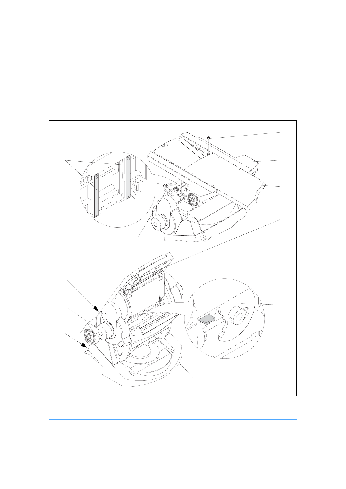
To clean the vertical tracks it is necessary to remove the platform. Proceed as follows:
Remove the payload (if fitted). It is not necessary to remove the wedge adaptor.
Release the sliding plate clamp (17). Use th e adjustment knob (13) to wind the sliding plate
(12) backwards until it is clear of fixing screws (19).
Level the platform.
Remove six screws (19) securing the platform (20) to the balance mechanism (21). Lift off
the platform.
Using a pipe cleaner (or similar) moistened with an isopropanol-based cleaner (3M VBH or
similar), clean the two vertical tracks (22). Upwards pressure on the balance mechanism
will allow the area of track under the vertical rollers to be cleaned.
13
Page 14
Install the platform (20) on the balance mechanism (21) and secure with six screws (19),
using Loctite 222E.
Using the adjustment knob (13) wind the sliding plate forwards to the central position.
Refit the payload (if required) and reba lance the head.
(19)
(22)
(17)
(14)
(20)
(12)
(13)
(21)
(23)
(5)
(24)
Cleaning balance mechanism tracks
14
Page 15

Horizontal tracks
No dismantling is necessary to clean the horizontal tracks. Proceed as follow:
Remove the payload (if fitted).
Set the balance mechanism to its maximum setting by pushing in the knob (14) and turning
it clockwise to its stop.
Tilt the platform fully backwards and apply the tilt brake (5).
Pull down the flap guard (24) to reveal t he be vel gear (23). Access to the horizontal tracks
is through the holes in the bevel gear, which may be rotated freely.
Using a pipe cleaner (or similar) moistened with an isopropanol-based cleaner (3M VBH or
similar), clean the two horizontal tracks. Upwards pressure on the balance mechanism will
allow the area of track under the horizontal rollers to be cleaned.
Release the flap guard (24) and the tilt brake (5) and return the platform to the horiz on ta l
position.
Refit the payload (if required).
15
Page 16
Routine maintenance
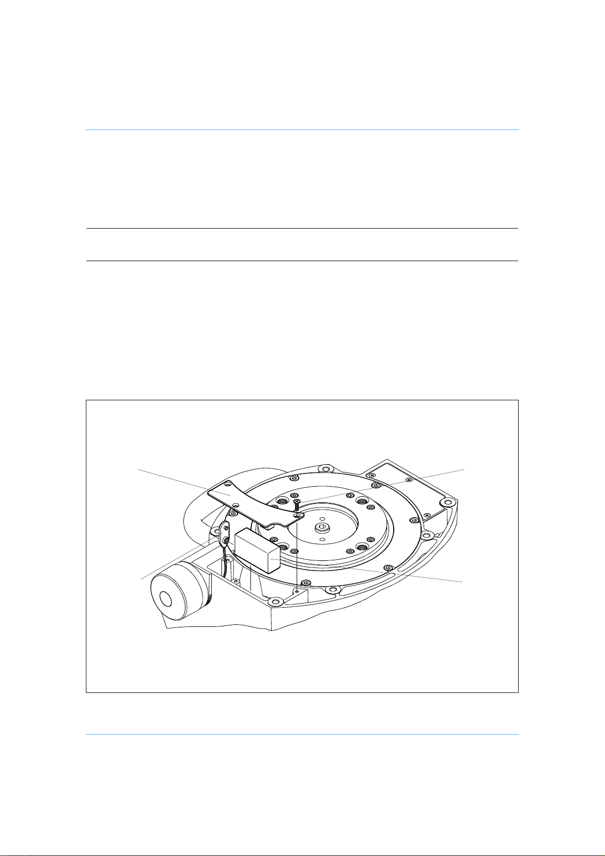
Level bubble illumination unit battery replacement
The level bubble on the Vector 700/700H pan and tilt head is illuminated by a battery-powered
light-emitting diode (LED). A time-delay circuit initiated by a switch controls the LED. The ba ttery
should be replaced at yearly intervals or whenever the illumination is considered inadequate.
NOTE: Dependent on the type of mounting, it may be necessary to remove the head
from the mounting for access to the battery compartment.
To install or replace the battery:
Remove three screws (25) which secure the battery compartment cover plate (28) to the
head.
Install or replace the battery (26), pushing the connector (27) onto the battery terminals.
Position the battery in the battery compartment, ensuring that the wiring is not trapped.
Refit the battery cover plate (28), ensuring battery locates in cover plate. Secure with three
screws (25).
Press the switch (7) and ensure the lamp is lit for approximately 15 seconds.
(28)
(27)
Level bubble illumination unit battery replacement
(25)
(26)
16
Page 17
Adjustments
After considerable use the platform slide clamp may require adjustment.
To enable the payload to be correctly balanced, the wedge adaptor may require repositioning.
The pan and tilt brakes may require adjustm en t after considerable use.
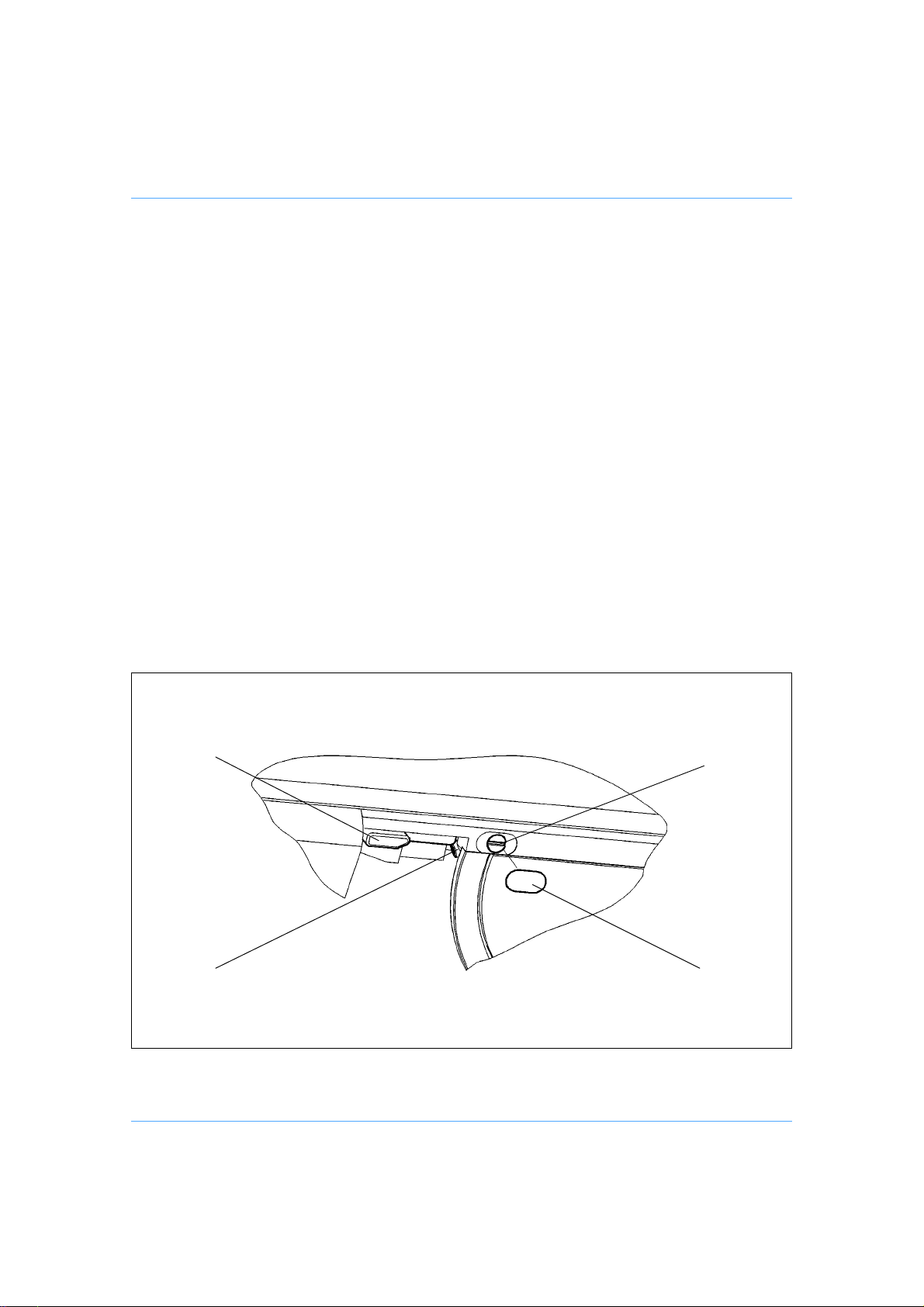
Platform slide clamp adjustment
The platform slide clamp should be set so that, in the up or clamped position it prevents the platform slide from being moved, while in the down or released position it allows free adjustment of the
slide. To adjust the clamp, proceed as follows:
On the right-hand side of the platform, carefully remove the self-adhesive label (17.2) to re-
veal the slotted shaft (17.1).
Pull the slide clamp lever (17) fully upwards.
Slacken the clamp screw (17.3).
Turn the slotted shaft (17.1) fully clockwise to apply the clamp.
Tighten the clamp screw (17.3).
Move the lever over its full range and ensure that, in the clamped position, it prevents the
slide from being moved, while in the released position it a llows free adjustm ent of the slide.
Re-adjust if necessary.
Replace the self-adhesive label (17.2) in the recess in the platform.
(17)
(17.3)
(17.1)
(17.2)
Platform slide clamp adjustment
17
Page 18
Repositioning the wedge adaptor
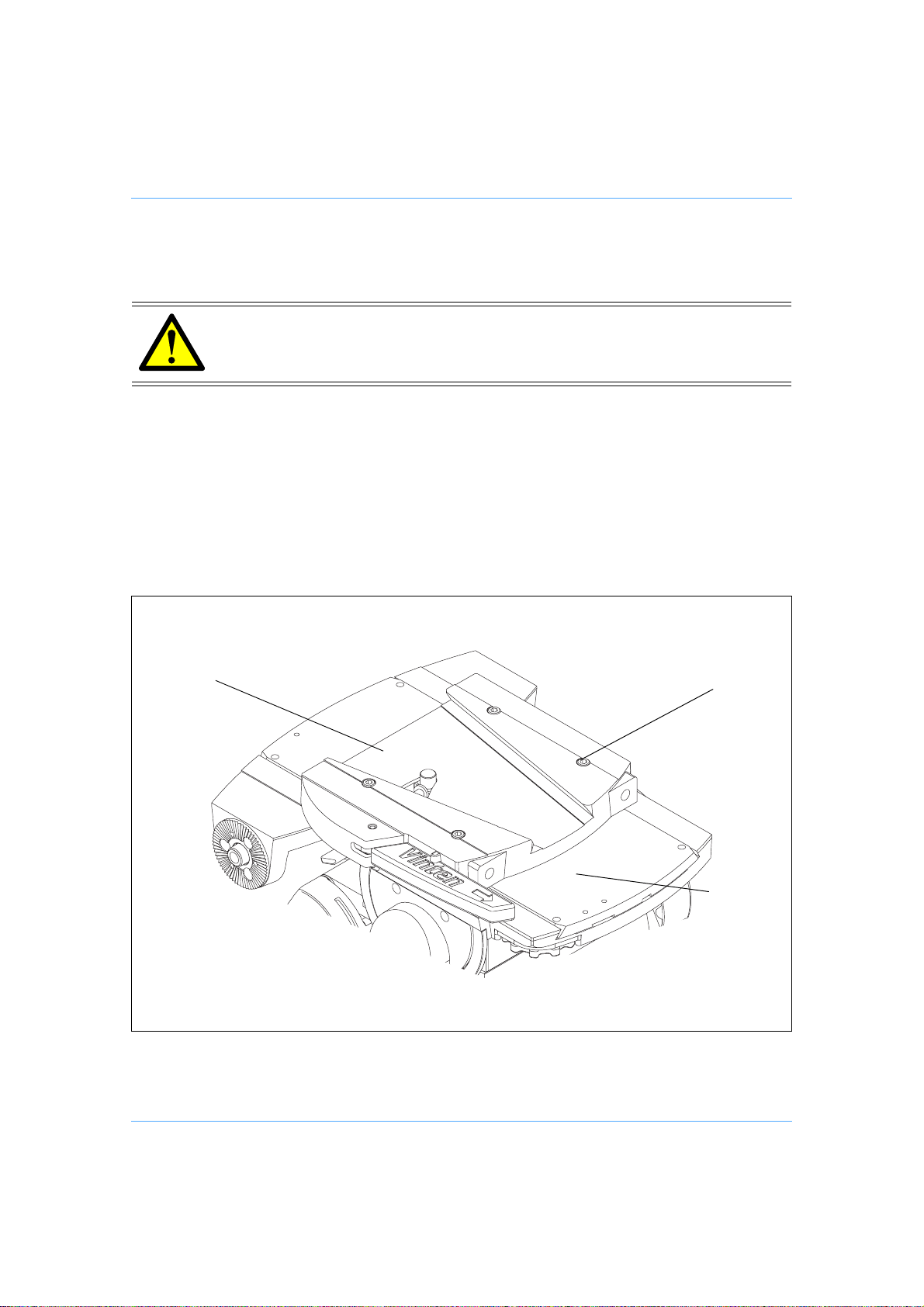
The wedge adaptor (1) is secured by four cap head screws (3) which pass through the wedge
adaptor into the sliding plate (12).
WARNING! Overlong screws will prevent the sliding plate from operating.
Always use the screws provided (M6 x 30 mm).
To reposition the wedge adaptor:
Engage the centre lock (See Locking the platform) and remove the load.
Hold the body of the wedge adaptor (1) and use a 4 mm hexagon wrench to remove four
securing screws (3).
Reposition the wedge adaptor (1) on the sliding plate (12), ensuring that the narrow end of
the wedge adaptor faces forwards
Insert the four screws (3) in the holes in the wedge adaptor and tighten.
(1)
(3)
(12)
Repositioning the wedge adaptor
18
Page 19
Pan and tilt brake adjustment
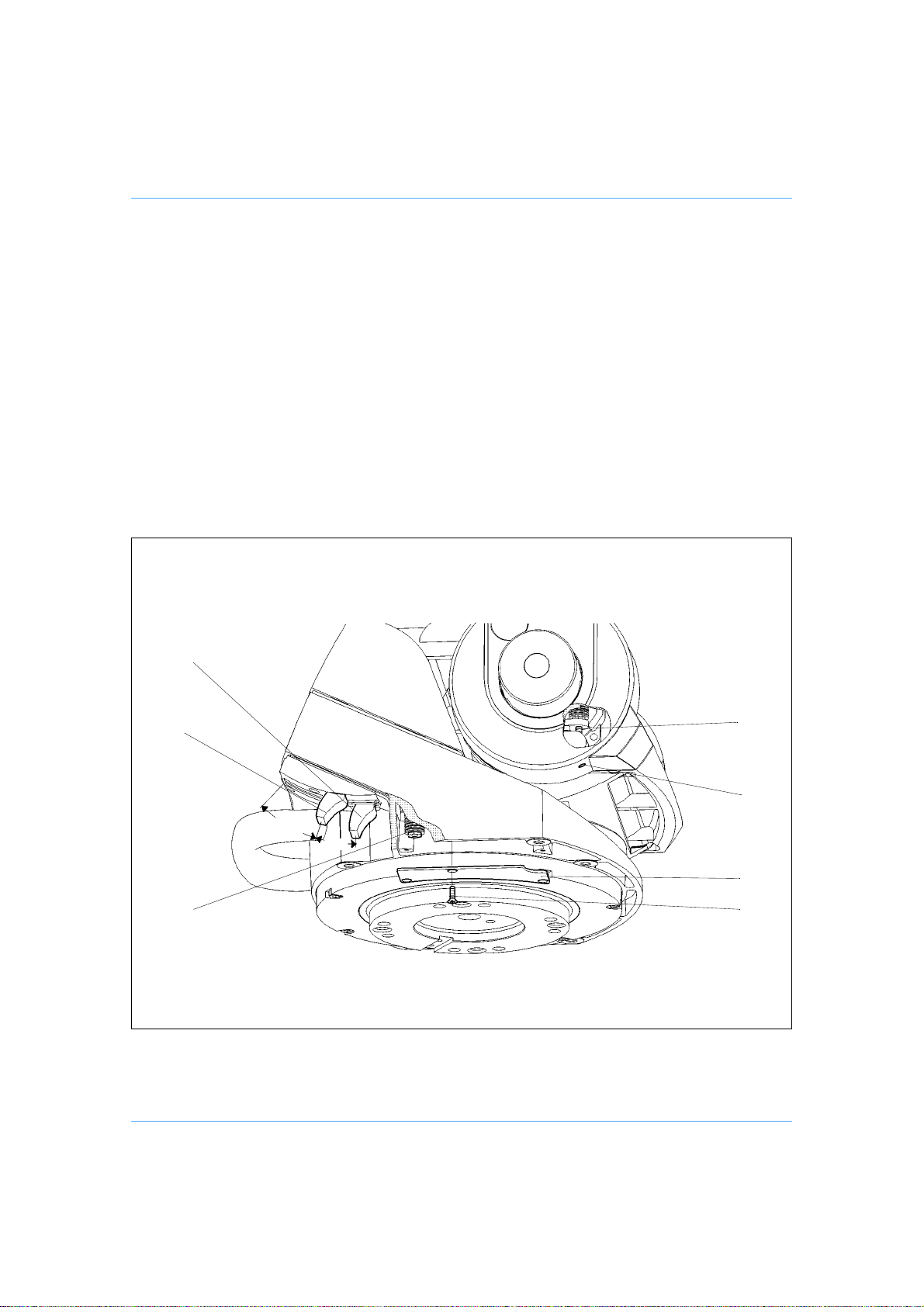
The pan and tilt brakes should be set so that the brakes begin to be applied after approximately
one-third of the lever travel.
The tilt brake is adjusted by inserting a 2 mm he xagon wrench through the hole (5.2) in the bottom
of the tilt unit cover and turning the grub screw (5.1). To adjust the tilt brake, proceed as follows:
Operate the tilt brake lever (5) from the OFF to the ON position.
If brake pressure is not felt after approximately one-third of the lever travel, turn the grub
screw (5.1) clockwise until this is achieved.
Operate the tilt brake lever (5) to the OFF position and ensure that the platform is free to
move.
(5)
(4)
(4.1)
(5.1)
(5.2)
2/3
1/3
(29)
(30)
Pan and tilt brake adjustment
19
Page 20

The pan brake is adjusted by turning the pin (4.1). To gain access to the pin it is necessary to re-
move the payload from the head, remove the head from its mounting and remove a cover plate
(29) from the underside of the head. To adjust the pan brake, proceed as follows:
WARNING! Remove the payload before adjusting the pan brake.
Remove the payload from the head.
Remove the head from its mounting.
On the underside of the head, remove three screws (30) securing cover plate (29).
Operate the pan brake lever (4) from the OFF to the ON position.
If brake pressure is not felt after approximately one-third of the lever travel, turn the pin (4.1)
clockwise until this is achieved.
Operate the pan brake lever (4) to the OFF position and ensure that the head is free to ro-
tate.
Refit cover plate (29) and secure with three screws (30).
20
Page 21

Parts List
The following list includes the main assemblies, user-replaceable sp are parts and optional acce ssories. For further information regarding repair or spare parts, please contact Vinten Broadcast
Limited or your local distributor.
For information on-line, visit our website at
www.vinten.com
Main assemblies
Vector 700 pan and tilt head - flat base (Gre y) 3448-3
Vector 700 pan and tilt head - Mitchell adaptor (Grey) 3448-5
Vector 700H pan and tilt head - flat base (Grey) 3448-3H
Vector700H pan and tilt head - Mitchell adaptor (Grey) 3448-5H
Vector 700 pan and tilt head - flat base (Black) 3458-3
Vector 700H pan and tilt head - flat base (Black) 3458-3H
Wedge adaptor (Grey) 3389-3
Wedge adaptor (Black) 3460-3
Camera wedge f or wedge adaptor 3391-3
Te lescopic pan bar and clamp (Grey) 3219-62
Te lescopic pan bar and clamp (Black) 3219-82
Fixed pan bar and clamp (Grey) 3219-65
Fixed pan bar and clamp (Black) 3219-94
Short fixed pan bar and clamp (Grey) 3219-66
Short fixed pan bar and clamp (Black) 3219-93
Fixing bolt L054-714
Washer - for fixing bolt L602-122
Spanner - for head bolts J551-001
User-replaceable spare parts
Battery - 9V, 6LR61 (PP3, 6AM6, MN1604, E-BLOCK or equivalent) C550-023
21
Page 22

Optional accessories
Lightweight Mitchell adaptor 3103-3
Heavy-duty Mitchell adaptor - for Vinten pedestal
mounting in conjunction with Hi-hat adaptor Part No. 3055-3 3724-3
Adaptor plate kit - for use on Hawk and Teal pedestals 3354-900SP
22
 Loading...