

Page 1
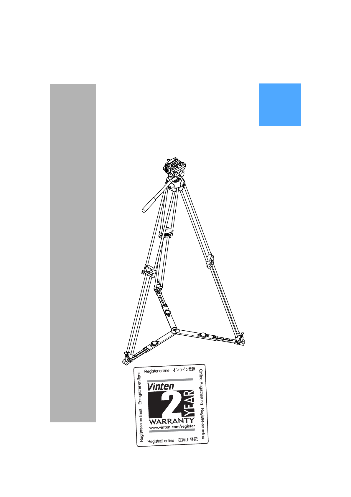
protouch
PRO-5
Plus
System
Vinten
Operators Guide
Camera Control Solutions
Page 2

protouch
PRO-5
Publication Part No. V4057-4980-EN
Issue 1
Original Instructions
System
Plus
Copyright © The Vitec Group plc 2009
All rights reserved throughout the world. No part of this document may be stored in a retrieval system, transmitted, copied
or reproduced in any way including, but not limited to, photocopy, photograph, magnetic or other record without the prior
agreement and permission in writing from the Vitec Group plc.
Vinten® is a registered trademark of The Vitec Group plc.
Page 3

Preface
Thank you and congratulations on your new
Protouch PRO-5
plus
system from Vinten
Back
We want you to get the most from your new PRO-5
read this operators guide to familiarize yourself with its many features, some of which may be new
to you. It also covers essential health and safety information and a section on maintenance that
will ensure you keep your new product in perfect condition.
To receive additional benefits, regi ster with Vinten now on line by visiting www.vinten.com/regi ster
(see Warranty Details and Terms and Conditions on page 25).
Features and benefits of your new PRO-5
The PRO-5plus system is perfectly suited for all types of event videography using the latest generation of small format digital Camcorders and DSLR's.
• 0 to 4.5kg (9.9lb) @ 55mm C of G
• Two-step (zero and 1) spring counterbalance system for positive camera control.
• Top-loading 'Side Load' quick-release slide plate, with 1/4 in. and 3/8 in. camera
screws and locating pin, accommodating the latest generation of digital Camcor d er s
and DSLR's.
• Integral 75mm ball base for reliable levelling.
• Pozi-Loc tripod c lamping system requires lo w effort with a 90° turn fr om on to off , providing the user with a positive indication that the tripod is securely locked.
• Single stage Aluminium Pozi-Loc tripod offering extensive height range, unrivalled
torsional stiffness, rapid setup and convenient carrying.
plus
system, and therefore encourage you to
plus
system
• Protouch branded Petrol system case.
Once again, thank you for choosing the PRO-5
plus
system.
We are confident it will give you many years of reliable
performance.
3
Page 4

Safety - Read This First
Warning Symbols in this Operators Guide
Where there is a risk of personal injury or injury to other s, comments appear
highlighted by the word WARNING!—supported by the warning tria ngle symbol.
Where there is a risk of damage to the product, associated equipment, process
or surroundings, comments appear highlighted by the word CAUTION!
Usage
Back
The Pro-5
balance a camera and ancillary equipment weighing up to 4.5 kg (9.9 lb). The Pro-5
intended for use by professional camera operators.
plus
system is designed for event videography and the corporate sector to support and
WARNING!
1. Do NOT attempt to use this product if you do not understand
how to operate it.
2. Do NOT use this pr oduct for any other purpose than that
specified in the Usage statement above.
3. Maintenance beyond that detailed in this Operators Guide
must be performed only by competent personnel in
accordance with the procedures specified in the Maintenance
Manual.
plus
system is
Further information
For full details on maintenance and spare parts, please refer to Protouch PRO-5
Maintenance Manual and Illustrated Parts List (Publicatio n Part No. V4057-4990) This is obtainable from Vinten or your local Vinten distributor. For inform ation on-line, visit our website at
www.vinten.com.
plus
System -
4
Page 5

Technical specification
Back
PRO-5
Weight:
Height to mounting face 11.2 cm (4.4 in.)
Length 12.1 cm (4.8 in.)
Width 15.3 cm (6.0 in.)
Load capacity (@ 55 mm centre of gravity) 4.5 kg (9.9 lb)
Counter balance on/off
Tilt range +90° -60°
Pan range 360°
Tripod fixing 75 mm ball
Operating temperature -10°C to 60°C
Pozi-Loc tripod
Levelling bowl diameter 75 mm
Maximum height with floor spreader 156.2 cm (61.5 in.)
Minimum height with floor spreader 41.6 cm (16.4 in.)
plus
pan and tilt head
Head with bowl clamp 1.65 kg (3.63 lb)
Pan bar 0.2 kg (0.44 lb)
Weight 3.2 kg (7.0 lb)
Transport length 71 cm (28.0 in.)
Recommended maximum load 25 kg (55 lb)
Floor spreader
Maximum leg radius 77 cm (22.5 in.)
Minimum leg radius 38 cm (15 in.)
Weight 0.7 kg (1.5 lb)
5
Page 6

Back
Contents
Page
Preface. . . . . . . . . . . . . . . . . . . . . . . . . . . . . . . . . . . . . . . . . . . . . . . . . . . . . . . . . . . . . . . . . . . . 3
Safety - Read This First . . . . . . . . . . . . . . . . . . . . . . . . . . . . . . . . . . . . . . . . . . . . . . . . . . . . . . 4
Technical specification. . . . . . . . . . . . . . . . . . . . . . . . . . . . . . . . . . . . . . . . . . . . . . . . . . . . . . . 5
Usage. . . . . . . . . . . . . . . . . . . . . . . . . . . . . . . . . . . . . . . . . . . . . . . . . . . . . . . . . . . . . . . . . . . . . 4
Further information. . . . . . . . . . . . . . . . . . . . . . . . . . . . . . . . . . . . . . . . . . . . . . . . . . . . . . . . . . 4
Introduction
PRO-5plus pan and tilt head . . . . . . . . . . . . . . . . . . . . . . . . . . . . . . . . . . . . . . . . . . . . . . . . 11
Pozi-Loc tripod. . . . . . . . . . . . . . . . . . . . . . . . . . . . . . . . . . . . . . . . . . . . . . . . . . . . . . . . . . . 12
Tripod spreader . . . . . . . . . . . . . . . . . . . . . . . . . . . . . . . . . . . . . . . . . . . . . . . . . . . . . . . . . . 12
Operation
Mounting the camera. . . . . . . . . . . . . . . . . . . . . . . . . . . . . . . . . . . . . . . . . . . . . . . . . . . . . . 14
Checking camera balance . . . . . . . . . . . . . . . . . . . . . . . . . . . . . . . . . . . . . . . . . . . . . . . . . . 15
Pan and tilt brakes. . . . . . . . . . . . . . . . . . . . . . . . . . . . . . . . . . . . . . . . . . . . . . . . . . . . . . . . 17
Pan and tilt drag. . . . . . . . . . . . . . . . . . . . . . . . . . . . . . . . . . . . . . . . . . . . . . . . . . . . . . . . . . 17
Optional equipment
Carrying strap . . . . . . . . . . . . . . . . . . . . . . . . . . . . . . . . . . . . . . . . . . . . . . . . . . . . . . . . . . . 18
Dollies . . . . . . . . . . . . . . . . . . . . . . . . . . . . . . . . . . . . . . . . . . . . . . . . . . . . . . . . . . . . . . . . . 18
Servicing
General . . . . . . . . . . . . . . . . . . . . . . . . . . . . . . . . . . . . . . . . . . . . . . . . . . . . . . . . . . . . . . . . 20
Cleaning. . . . . . . . . . . . . . . . . . . . . . . . . . . . . . . . . . . . . . . . . . . . . . . . . . . . . . . . . . . . . . . . 20
Routine maintenance. . . . . . . . . . . . . . . . . . . . . . . . . . . . . . . . . . . . . . . . . . . . . . . . . . . . . . 20
Adjustments. . . . . . . . . . . . . . . . . . . . . . . . . . . . . . . . . . . . . . . . . . . . . . . . . . . . . . . . . . . . . 21
Parts list. . . . . . . . . . . . . . . . . . . . . . . . . . . . . . . . . . . . . . . . . . . . . . . . . . . . . . . . . . . . . . . . . . 24
Warranty Details and Terms and Conditions . . . . . . . . . . . . . . . . . . . . . . . . . . . . . . . . . . . . 25
Associated publications
Protouch PRO-5
Publication Part No. V4057-4990
plus
System - Maintenance Manual
6
Page 7

Back
(1)
(2)
(3)
(4)
(5)
(7)
(6)
(8)
(9)(11)
(13)
(14)
(16)
(17)
(15)
(10)
(12)
Fig. 1 PRO-5
Plus
Pan and Tilt Head
7
Page 8

Back
(1) Tilt drag control
(2) 1/4 in. camera screw
(3) 3/8 in. camera screw stowage
(4) 3/8 in. camera screw
(5) Pan bar
(6) Camera slide plate bung
(7) Levelling bubble
(8) Pan drag con trol
(9) Pan bar mounting
(10) Pan brake
(11) Bowl clamp
(12) Balance selector
(13) Tilt brake
(14) Camera slide plate release
(15) Camera slide plate clamp
(16) Locating pin
(17) Camera slide plate
8
Page 9
Back
(18)
(19)
(20)
(21)
(23)
(22)
(24)
(25)
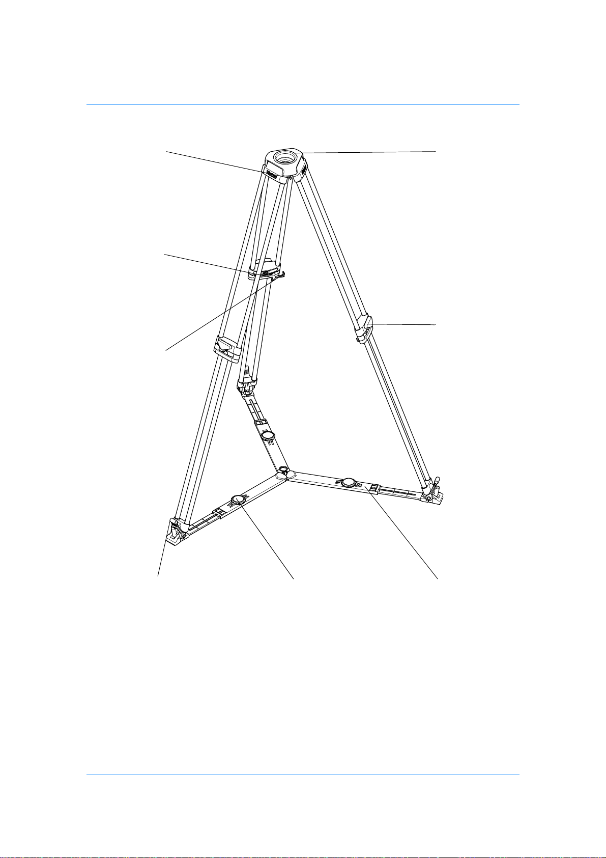
Fig. 2 Pozi-Loc Tripod and Floor Spreader
9
Page 10

Back
(18) Tripod bowl
(19) Clamp knob
(20) Floor spreader
(21) Floor spreader adjuster
(22) Foot securing strap
(23) Leg tie strap
(24) Attachment point for mid-level spreader
(25) Tie down hook
10
Page 11

Introduction
Back
The protouch PRO-5
Loc single-stage tripod, a floor spreader and a soft case.
PRO-5
The PRO-5
cameras, up to 4.5 kg (9.9 lb) in weight. It embodies fluid drag assemblies for pan and tilt motions
with brakes on each axis to lock the head in any position. A levelling bubble is fitted to the rear of
the head and a quick-release, side-loading adju stable slide plate is provided for camera mounting.
A single fixed pan bar is supplied.
plus
plus
plus
system from Vinten comprises of a PRO-5
pan and tilt head
pan and tilt head (Fig. 1) is designed to support the latest professional digital video
plus
pan and tilt head, a Pozi-
Balance
The PRO-5
lb) at a centre of gravity (C of G) height o f 55 mm (2.2 in.) or may be deselected for free tilt rotation.
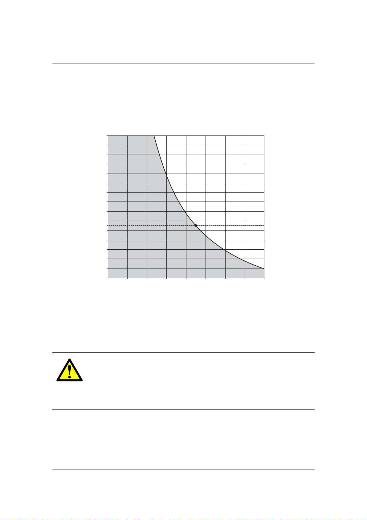
The graph (Fig. 4) shows the relationship between C of G height and payload for optimum performance.
plus
pan and tilt head’s two-step balance system is set for payloads up to 4.5 kg (9.9
Pan and tilt drag
Both the pan and tilt mechanisms incorporate fluid drag assemblies to en sure smooth movement
of the camera about these axes and are f itted with cont rol knobs (1) (8) to adjust the drag setting.
Pan and tilt brakes
Brakes (10) (13) on each axis are provided to lock the head in any position
Levelling bubble
To enable the head to be levelled, a levelling bubble (7) is fitted to the rear of the head.
Camera mounting
The camera is attached to the head by means of a slide plate (17), which is provided with a springloaded locating pin (16) an d 1/4 in. (2) and 3/8 in. (4) screws. When not in use, the screws are
stowed in the camera mounting platform (3). The slide plate (17) is loaded from above into the
side-loading clamp mechanism, and a clamp (15) is provided to hold the slide plate in position.
The release button (14) allows removal of the slide plate (17) from the head.
Pan bar
Pan bar mounting points (9) are located at the rear of the head, on either side of the camera
mounting platform. The pan bar (5) is attached using a pan bar clamp , with ang u lar adju stm e nt
available on the mount serrations. A single fixed pan bar (5) is supplied. A second pan bar may
be fitted.
11
Page 12

Back
Pozi-Loc tripod
The Pozi-Loc single-stage tripod (Fig. 2) has aluminium legs and a 75 mm levelling bowl (18). It
is fitted with the highly-efficient Pozi-Loc leg clamp (19), which provides quick set-up and easy adjustment.
Tripod spreader
The tripod is supplied with a floor spreader (Fig. 2) which increases the rigidity of the tripod. The
floor spreader which, being flexible, compen sates for uneven ground, p rotects floors a nd carpets
and prevents the tripod legs sinking into soft ground. It should be used at all times.
Each arm of the spreader is adjustable for length (21) and the tripod feet are secured by rubber
straps (22). At the fullest extension of the spreader, and with all tripod legs fully retracted, the tripod can be used at its lowest operating height.
WARNING!
Do NOT use the tripod without a spreader to obtain a lower height, the
tripod geometry will become unstable.
NOTE: The spreader may be removed and the tripod fitted to a dolly.
12
Page 13

Operation
Assembly
If not already done, assemble the system as follows:
Tripod and floor spreader
To install the floor spreader (Fig. 2):
Lift the tripod out of the case using the finger holes just below the top clamps.
Release the leg tie strap (23) and spread the legs.
Secure the spreader to the tripod feet with the rubber straps (22).
NOTE: Once assembled, keep the spreader attached to the tripod.
To adjust the tripod:
Back
Adjust the operating height by undoing t he leg clamps (19) and pulling the tripod up to the
desired height. Adjust the spreader (21) if necessary.
Tighten the clamps (19) until an audible click is heard and the knob is in the horizontal,
locked position.
In adverse conditions secure the tripod using the tie-down hook (25), or su spend a weight
from the hook.
1. Always set the floor spreader to the widest practicable setting to
increase stability. Use care when the tripod is fully extended and
the floor spreader is in the closed position, as stability will be
reduced.
2. Do NOT hang items on pan bar handles (5). This will severely
reduce tripod stability.
3. Use care when setting the tripod on uneven s urface s, pa rticularly
stairs—stability will be reduced. Using a mid-level spreader is
recommended on stairs (see Optional accessories on page 24).
4. Secure the tripod using the tie-down hook (25) if the tripod is
mounted in an elevated position above personnel—such as a
platform or gantry.
WARNING!
13
Page 14
Pan and tilt head
1
2
(15)
Back
The PRO-5
able which enable the head to be installed on tripods or pedestals fitted with other mountings.
These are listed under Optional accessories.
To install the head, remove the bowl clamp assembly (11) fr om the head, position the head on the
tripod and refit the bowl clamp assembly f rom below. Level th e he ad with t he ai d of t he leve l bubble (7) and tighten the bowl clamp (11).
plus
pan and tilt head (Fig. 1) is supplied with a 75 mm ball mount. Adaptors are avail-
Mounting the camera
Remove the slide plate (17) from the head by releasing the slide plate clamp (15), pressing the
slide lock release (14) and lifting the plate upward.
Install the required camera fixing screw (2) or (4) in the slide plate and retain with the rubber b ung
(6). Stow the unused screw in the appropriate stowage (3) in the platform.
Attach the slide plate (17) to the camera or camera mounting plate approximately under the centre
of the camera's weight using the fixing screw (2) or (4) and locating pi n (16) (if appropriate).
Set the platform level and apply both the pan (10) and tilt brakes (13).
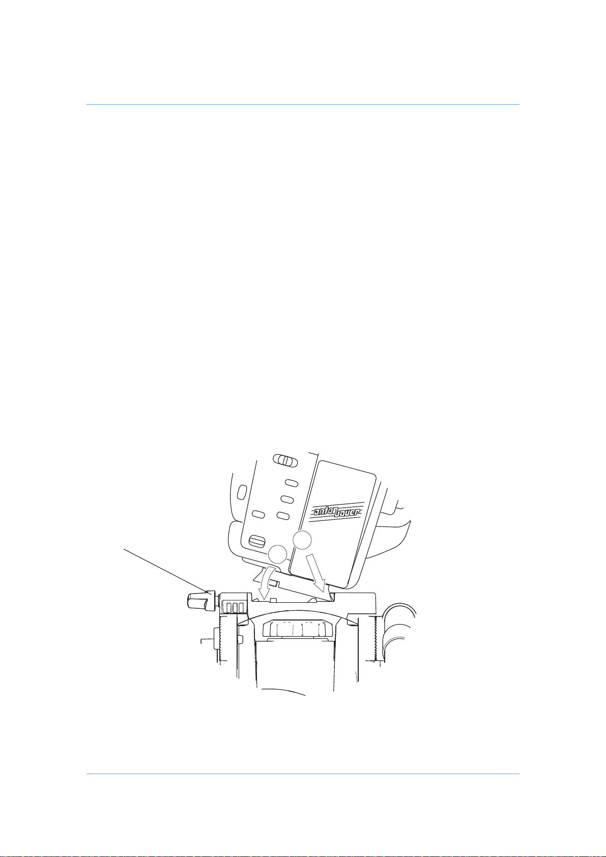
Lower the camera onto the plat form (Fig. 3) ensuring that the edge of the slide plate opposite t he
slide clamp engages first, and then push downward so the slide clamp ‘snaps’ into position.
Tighten the slide plate clamp (15).
Fig. 3 Mounting the camera
14
Page 15
Back
mm
kg
0
10
20
30
40
50
60
70
80
90
100
110
120
130
140
150
0 12345678
Payload
Centre of Gravity (C of G) Height
Checking camera balance
The PRO-5plus head has an on/off selectable balance system, set for payloads of 4.5kg (9.9lb)
at a centre of gravity (C of G) height of 55 mm (2.2 in. ). The gr aph (Fig. 4) shows the relationship
between C of G height and payload for optimum performance.
Fig. 4 Balance graph
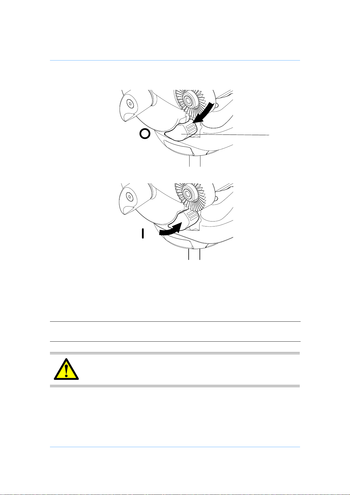
The balance selector (12) allows two balance levels to be utilized. Pushing the selector (12) downward (Fig. 5) offers free rotation of the tilt axis with no counter-balance engagement. Lifting the
selector (12) upward (Fig. 5) offers full balance capacity (Fig. 4).
1. Do NOT exceed the maximum capacity of either the head or the
tripod. The system will become unstable and may fail.
2. Always support the camera payload if disengaging the counterbalance mechanism to prevent it falling away suddenly.
3. Keep hands clear of the moving platform to avoid trapping
fingers.
WARNING!
15
Page 16
Back
(12)
Fig. 5 Balance selector
Check the camera balance as follows, ensuring that the pan bar(s) (5) and any ancillary equip-
ment have been fitted:
Reduce tilt drag (1) to minimum level.
NOTE: When changed, the selected balance le ve l (12) engages as th e platform moves
through the horizontal position.
Steady the camera payload using the pan bar. Be prepared to prevent the
WARNING!
head falling away suddenly. Keep hands clear of the moving platform to
avoid trapping fingers.
Release the tilt brake (13).
Using the pan bar (5), tilt the head backwards and forwards to de termine if th e camera po-
sition is equally balanced in both directions. If not, set the platform level and apply the tilt
brake (13). Position the camera correctly on the head by releasing the slide plate clamp (15)
16
Page 17

Back
and sliding the camera backwards or forward until it balances horizontally. Apply the slide
plate clamp (15). Re-check and adjust as necessary.
Using the pan bar (5), tilt the head backwards and forwards. If the head tends to spring
back, de-select the balance system (12) and apply sufficient tilt drag (1) to co nt ro l camera
tilt as required. If the head tends to fall away, the payload exce eds the capacity of the head
(Fig. 4). If possible, reduce the C of G height of any ancillary equipment or remove com-
pletely.
Securely apply the slid e plate clamp (15) when balance has been achieved,
to prevent the camera payload slipping.
WARNING!
Pan and tilt brakes
Brakes on each axis allow the head to be locked at any chosen position. The operating lever for
the pan brake (10) is at the rear of the head. The tilt brake (13) is operated by a lever on the lefthand side of the head.
To apply the pan brake, turn the lever (10) fully clockwise. To release the brake, turn the lever
counter-clockwise.
To apply the tilt brake, turn the lever (13) fully clockwise. To release the brake, turn the lever counterclockwise.
CAUTION! DO NOT use the brakes to supplement drag, the head may be damaged.
When the brakes are not in use, always ensure they are fully released.
Pan and tilt drag
Both the pan and tilt mechanisms incorporate a fluid drag system to ensure smooth movement of
the camera about these axes.
The tilt drag adjustment knob (1) is on the left-hand side of the head, the pan drag knob (8) is on
the top of the body, beneath the platform.
To increase drag, turn the appropriat e kn ob clockwise. To decrease drag, turn the knob counterclockwise.
CAUTION! Reduce drag to a minimum when the head is out of use f or long periods, to
minimize wear on drag components.
17
Page 18

Back
Optional equipment
Carrying strap
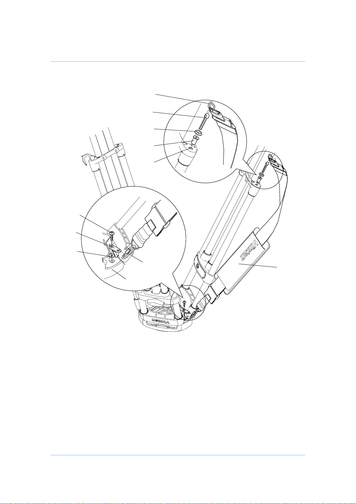
A carrying strap (26) is available as an optional accessory and is installed as follows (Fig. 6):
On the lower moulding of the leg with the strap, drive in the 'knock-out' (23.1) using a suitable tool. If possible, remove the b lank from inside the moulding to preven t subsequent rattle.
Push a blind captive nut (26.4) into the hole in the lower moulding.
Using a suitable M5 screw, fully compress the blind captive nut. Remove the M5 screw.
Install a washer (26.3) on the lower strap anchor (26.2) a nd screw into the captive nut
(26.4). Ensure that the hole in the strap anchor is oriented so that the ka rabiner (26.1) can
be attached.
On the underside of the tripod bowl (18), remove and discard the screw (26.5) securing the
corresponding leg clamp (18.2). Do not remove the washer (18.1).
Position the bowl strap anchor (26.6) on the leg clamp, ensuring it is correctly oriented. Us-
ing Loctite 221, secure the bowl strap anchor (26.6) with the 25 mm M6 screw (26.5) supplied with the strap. Tighten screw to a torque of 4.5 Nm (40 lbf in.).
Using the karabiners (26.1), clip the strap (26) to the strap anchors and adjust to length.
Dollies
The PRO-5
der Optional accessories on page 24.
plus
system may be mounted on a variety of OB and studio dollies, which are listed un-
18
Page 19
Back
(26.3)
(26.2)
(26)
(26.4)
(23.1)
(26.5)
(26.6)
(18.1)
(26.1)
(26.1)
(18)
(18.2)
Fig. 6 Carrying strap
19
Page 20

Back
Servicing
General
Protouch products are robustly made to high engineering standards and little attention is required
to maintain serviceability save regular cleaning. Attention to the following points will ensure a long
and useful service life with minimum need for repair.
Cleaning
During indoor use, the only cleaning required should be a regular wipe over with a lint-free cloth.
Dirt accumulated during storage may be removed using a semi-stiff brush. Particular attention
should be paid to the ball mounting face of the h ead, the spa ce between the tilt ing assembly and
the base and the mounting bowl of the tripod.
Use out-of-doors under adverse conditions will require special attention. Salt spray should be
washed off with fresh water at the earliest opportunity. Sand and dirt acts as an abrasive and
should be removed using a semi-stiff brush or vacuum cleaner.
CAUTION! DO NOT use solvent or oil-based cleaners, abrasives or wire brushes to
remove accumulat ions of dirt, as these damage the protective surfaces.
Use only detergent-based cleaners.
Routine maintenance
During use, check the following:
Check the effectiveness of the pan and tilt brakes. Reset as necessary.
Check the effectiveness of the tripod leg clamps. Reset as necessary.
Check for ageing and cracking of the rubber foot securing straps on the spreader and renew
if necessary.
No further routine maintenance is required.
20
Page 21

Back
Adjustments
Pan brake knob adjustment
Because its movement is restricted, the pan brake knob (10) may require adjustment after prolonged use.
To adjust the pan brake knob (Fig. 7):
Remove the securing screw (10.1) and pull the knob (10) off the shaft (10.2).
Turn the shaft (10.2) clockwise until the pan brake is fully applied.
Install the knob (10) on the shaft (10.2) positioned just beyond right angles (clockwise) to
the body of the head.
Turn the knob fully counterclockwise and ensure th e brake is released. Turn the knob clock-
wise and ensure the brake is applied before the knob reaches the end of its travel.
Readjust as necessary and secure the knob with the screw (10.1).
Tilt brake knob adjustment
The tilt drag knob (13) may also require adjustment after prolonged use:
To adjust the tilt brake knob (Fig. 7):
Remove the securing screw (13.1) and pull the knob (13) off the shaft (13.2).
Turn the shaft (13.2) clockwise until the pan brake is fully applied.
Install the knob (13) on the shaft (13.2) with the lever approximately horizontal in a 3 o’clock
position, pointing toward the rear of the head.
Turn the knob counterclockwise by half a turn and ensure the brake is released. Turn the
knob clockwise and ensure the brake is applied before the knob reaches the end of its travel
or interferes with other head controls.
Readjust as necessary and secure the knob with the screw (13.1).
21
Page 22
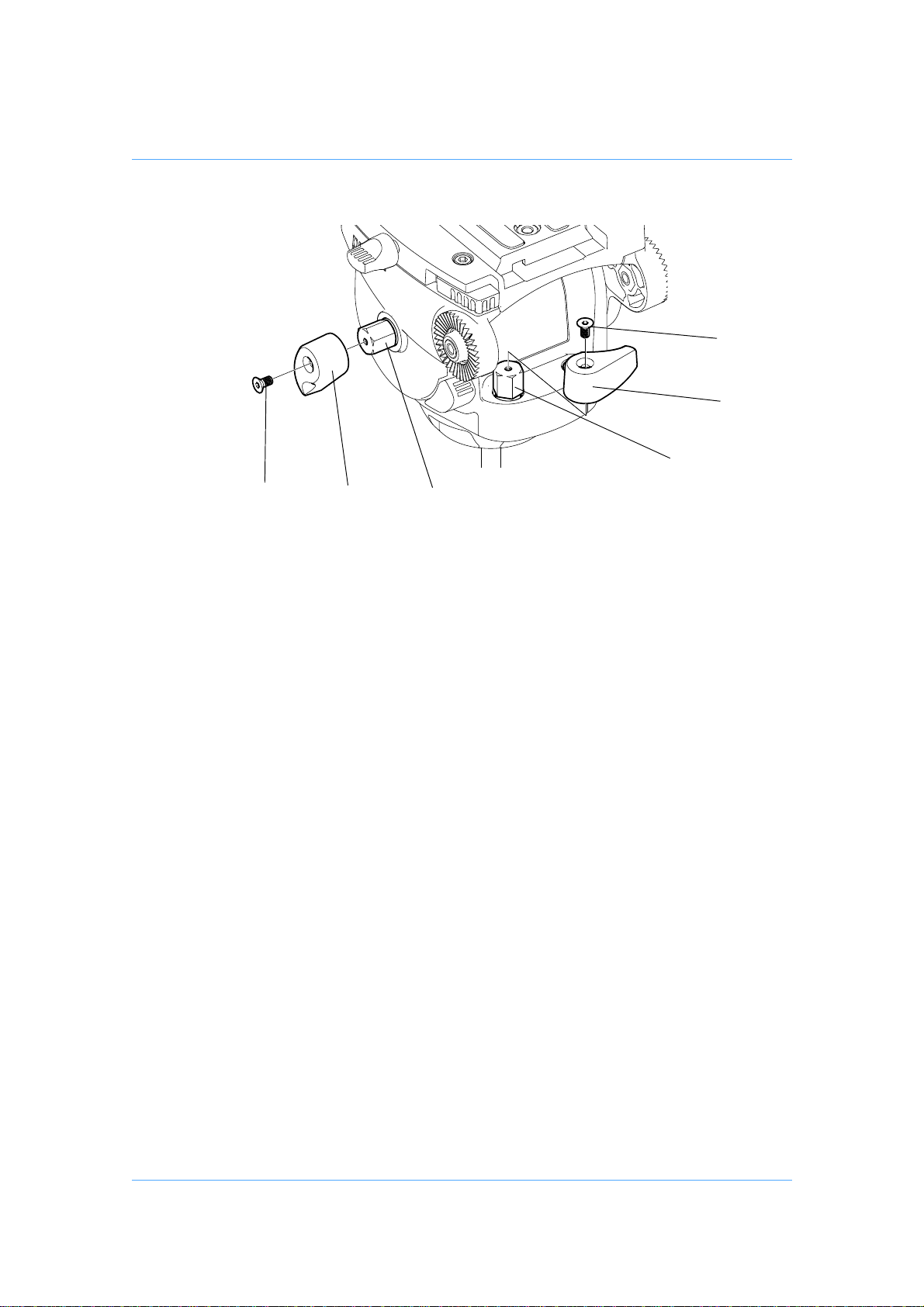
Fig. 7 Pan and Tilt brake adjustments
(10.1)
(10)
(10.2)
(13.2)
(13)
(13.1)
Back
‘Pozi-Loc’ tripod leg clamp adjustment
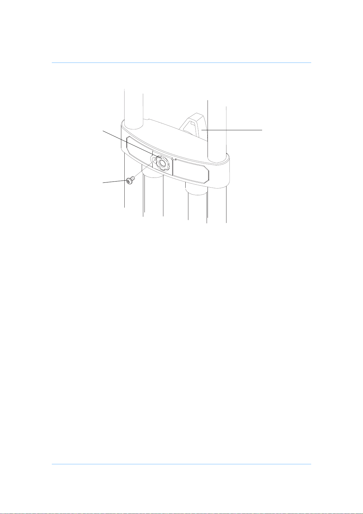
Bedding-in occurs with ‘Pozi-Loc’ leg clamps, which may necessitate resetting the clamp. Check
the effectiveness of each leg clamp and adjust as follows (Fig. 8):
Turn the clamp knob (19) to the vertical, ‘off’ position.
Remove screw (19.1). Using a suitable peg spanner, back off the threaded insert (19.2) slot
by slot until the leg is free to move under its own weight.
While sliding the leg in and out, gradually t ighten the thr eaded insert (19.2) until the clamp
begins to grip.
If not aligned, back off the threaded insert (19.2) until a slot aligns with the hole for screw
(19.1).
Back off the threaded insert (19.2) a further three slots.
Install screw (19.1) to secure the threaded insert (19.2).
22
Page 23
Back
(19.1)
(19.2)
(19)
Fig. 8 Pozi-Loc tripod leg clamp
23
Page 24

Back
Parts list
The following lists include main assemblies, user-replaceable spare parts and optional accessories. For further information regarding repair or spare parts, please contact Vinten or your local
Vinten distributor.
For information on-line, visit our website at
www.vinten.com.
Pro-5plus System
PRO-5
and floor spreader PRO5 AP1 F
plus
pan and tilt head, ENG Pozi-Loc single-stage tripod
Carrying case
Soft case for Protouch systems U005-190
User-replaceable spare parts
Pan bar U005-620
Optional accessories
Carrying strap
Carrying strap 3425-3P
Mid-level spreader V4032-0001
Set of three feet (for use with mid-level spreaders) 3378-902SP
Dollies
PD114 dolly U005-103
ENG (OB) dolly 3319-3B
ENG (Studio) dolly 3319-3C
ENG (OB) dolly - small 3319-3ST
Tripod and pedestal adaptors
75 mm ball to 100 mm bowl adaptor U005-159
24
Page 25

Back
Warranty Details and Terms and Conditions
Please read the Warranty Details and Terms and Conditions below.
Register your product to get One Extra Years Warranty and a Free
Vinten Quality Gift.
Please register now on-line at www.vinten.com/register—it's easy and fast.
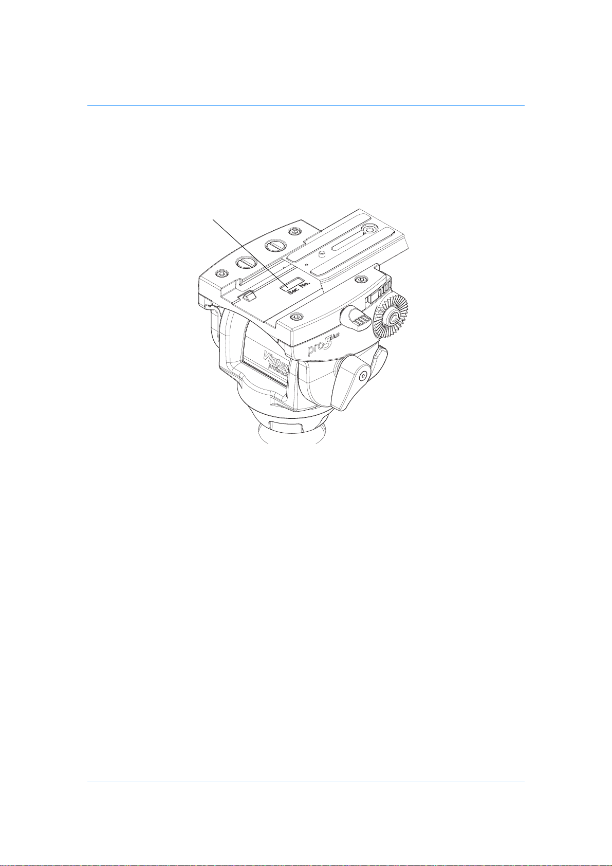
The product serial number location (27) is shown in Fig. 9.
Warranty
Vinten warrants, to the original purchaser only, that this product will be free from defects in materials and
workmanship under normal and proper usage for a period of one (1) year from the date of purchase.
Vinten's obligation under this warranty is limited to replacing or repairing, at Vinten's option, products or
parts determined by Vinten to be defective in materials or workmanship. This Vinten parts and labour
warranty is subject to the terms and conditions set forth below .
Extended Warranty
By registering on-line, the warranty on Vinten hardware products described above is extended from one (1)
to two (2) years from the date of purchase subject to the terms and conditions below.
Terms and Conditions
Notification of Warranty Claims
All warranty claims must be made in writing and must include date and proof of purchase
Extent of liability
This warranty is given to the original purchaser of the goods only and cannot be assigned, except with the
prior written agreement of Vinten.
Subject to these terms and conditions, Vinten will repair or replace, free of charge, any product or defective
part provided that the defective part of the product has been returned to Vinten or its authorized agent,
freight pre-paid.
If any defective product has been superseded and cannot be repaired, replacement will be made with a
current model of the same quality and equivalent function.
Exclusion of Liability
This warranty does not cover any damage, defects or costs caused by: (1) modification, alteration, repair or
service of the product by anyone other than Vinten or its authorized representative; (2) physical abuse to,
overload of, or misuse of, the product, or operation of the product in a manner contrary to the instructions
accompanying the product; (3) any use of the product other than that for which it was intended; or (4)
shipment of the product to Vinten for service.
UNDER NO CIRCUMSTANCES SHALL VINTEN BE LIABLE FOR ANY SPECIAL, INCIDENTAL OR
CONSEQUENTIAL DAMAGES, INCLUDING, BUT NOT LIMITED TO, PERSONAL INJURY, PROPERTY
DAMAGE, DAMAGE TO OR LOSS OF EQUIPMENT, LOST PROFITS OR REVENUE, COSTS OF
RENTING REPLACEMENTS AND OTHER ADDITIONAL EXPENSES, EVEN IF VINTEN HAS BEEN
ADVISED OF THE POSSIBILITY OF SUCH DAMAGES. SOME JURISDICTIONS DO NOT ALLOW THE
EXCLUSION OR LIMITATION OF INCIDENTAL OR CONSEQUENTIAL DAMAGES, SO THE ABOVE
LIMITATION OR EXCLUSION MAY NOT APPLY TO YOU.
ANY EXPRESS WARRANTY NOT PROVIDED HEREIN, AND ANY REMEDY WHICH, BUT FOR THE
WARRANTY CONTAINED HEREIN, MIGHT ARISE BY IMPLICATION OR OPERATION OF LAW IS
HEREBY EXCLUDED AND DISCLAIMED INCLUDING THE IMPLIED WARRANTIES OF
25
Page 26
Back
(27)
MERCHANTABILITY AND OF FITNESS FOR A PARTICULAR PURPOSE. SOME JURISDICTIONS DO
NOT ALLOW LIMITATIONS ON IMPLIED WARRANTIES, SO THE ABOVE LIMITATION MAY NOT APPLY
TO YOU.
THIS WARRANTY GIVES YOU SPECIFIC LEGAL RIGHTS AND YOU MAY ALSO HA VE OTHER RIGHTS,
WHICH MAY V ARY FROM JURISDICTION T O JURISDICTION.
Fig. 9 Serial Number Location
26
Page 27

Vinten
CHINA
The Vitec Group plc China
Room 1806, Hua Bin Building
No.8 Yong An Dong Li
Jian Guo Men Wai Ave
Chao Yang District
Beijing, P.R.China 100022
Tel: +86 10 8528 8748
Fax: +86 10 8528 8749
FRANCE
Camera Dynamics sarl
171, Avenue des Grésillo ns
92635 GENNEVILLIERS Cedex
France
Tel: +33 820 821 336
Fax: +33 825 826 181
GERMANY
Camera Dynamics GmbH
Gebäude 16
Planiger Straße 34
55543 Bad Kreuznach
Germany
Tel: +49 671 / 483 43 30
Fax: +49 671 / 483 43 50
Camera Dynamics GmbH
Erfurter Straße 16
85385 Eching
Germany
Tel: +49 89 / 321 58 200
Fax: +49 89 / 321 58 227
Back
JAPAN
Vinten Japan KK
P.A. Bldg. 5F
3-12-6 Aobadai
Meguro-ku Tokyo 153-0042
Japan
Tel: +81 3 5456 4155
Fax: +81 3 5456 4156
SINGAPORE
Camera Dynamics Pte Ltd
6 New Industrial Road
#02-02 Hoe Huat Industrial Building
Singapore 536199
Tel: +65 6297 5776
Fax: +65 6297 5778
UK
Camera Dynamics Ltd
William Vinten Building
Western Way
Bury St. Edmunds
Suffolk IP33 3TB
England
Tel: +44 1284 752 121
Fax: +44 1284 750 560
Sales Fax: +44 1284 757 929
USA
Camera Dynamics Inc.
709 Executive Blvd
Valley Cottage
NY 10989
USA
Tel: +1 845 268 0100
Fax: +1 845 268 0113
Toll Free Sales: +1 888 2 Vinten
Vinten Websit e www.vinten.com
Information contained in this document is
subject to change.
Vinten reserves the right, without notice, to
make changes in equipment design or
performance as progress in engineering,
manufacturing or technology may warrant.
Publication Part No. V4057- 4980-EN
 Loading...