

Page 1
HDT
Heavy-Duty
Tripod Range
Vinten
Operators Guide
Camera Control Solutions
Page 2

HDT
Heavy-Duty
Tripod Range
Publication Part No. 3901-8 Issue 2
Copyright © Vinten Broadcast Limited 2004
All rights reserved throughout the world. No part of this document may be stored in a retrieval system. transmitted, copied
or reproduced in any way including, but not limited to, photocopy, photograph, magnetic or other record without the prior
agreement and permission in writing of
Vinten Broadcast Limited.
Vinten and Quickfix are registered trademarks of Vinten Broadcast Limited.
Page 3

Preface
Thank you and congratulations on your new HDT Heavy-Duty
Tripod from Vinten
We want you to get the most from your new HDT Heavy-Duty Tripod, and therefore encourage
you to read this operators guide to familiarise yourself with its many features, some of which may
be new to you. It also covers essential health and safety information and a section on maintenance
that will ensure you keep your new product in perfect condition.
To receive additional benefits, register with Vinten now, on line by visiting www.vinten.com/register, or by completing the registration form.
Features and benefits of your new HDT Heavy-Duty Tripod
• Innovative new clamping system provides simple operation and confident clamping.
• Laser-engraved leg graduations, integral levelling bubble and folding carrying handle
assist rapid deployment.
• Three-position swivel foot provides a spike for soft ground, a self-levelling foot pad
for hard surfaces and a socket for dollies and floor spreaders.
• Rugged fixed -length mid-level spreader provides stability on uneven terrain.
Once again, thank you for choosing the HDT Heavy-Duty Tripod.
We are confident it will give you many years of reliable
performance.
3
Page 4

Safety - Read This First
Warning Symbols in this Operators Guide
Where there is a risk of personal injury, injury to others, or damage to the tripod
or associated equipment, comments appear, highlighted by the word WARN-
ING! and supported by the warning triangle symbol.
Technical data
Tripod HDT-1 HDT-2
Maximum height with floor spreader123 cm (48.4 in.) 146 cm (57.5 in.)
Minimum height with floor spreader 59 cm (23.2 in.) 51.1 cm (20.1 in.)
Weight 13.5 kg (29.7 lb) 15.3 kg (33.7 lb)
Transport length 78 cm (30.7 in.) 72.5 cm (28.5 in.)
Recommended maximum load 140 kg (308 lb) 120 kg (265 lb)
Elevation Unit
Load capacity with HDT-1 tripod 113 kg (250 lb)
Weight 5 kg (11 lb)
on-shot stroke 45.8 cm (18.0 in.)
Minimum height with HDT-1 tripod and floor spreader 71.5 cm (28.1 in.)
Maximum height with HDT-1 tripod and floor spreader 181.2 cm (71.3 in.)
Dolly Studio OB
Load capacity 160 kg (352 lb) 160 kg (352 lb)
Weight 9 kg (19.8 lb) 9 kg (19.8 lb)
Folded size 28.1 cm x 75.7 cm x 24 cm 28.1 cm x 76.6 cm x 26.2 cm
11 in. x 29.8 in. x 9.4 in (11 in. x 30.2 in. x 10.3 in)
Leg radius 50 cm (19.7 in.) 50 cm (19.7 in.)
Wheel diameter 12.5 cm (5 in. 15 cm (6 in.)
Height to tripod mounting 22.9 cm (9 in.) 25.2 cm (9.9 in.)
Tracking dolly
Load capacity 160 kg (352 lb)
Weight 11 kg (24 lb)
Folded size 36 cm x 64.4 cm x 23 cm (14 in. x 26 in. x 9 in.)
4
Page 5

Further information
For full details on maintenance and spare parts, please refer to HDT Heavy-Duty Tripod - Maintenance Manual and Illustrated Parts List (Publication Part No. 3901-9) This is obtainable from Vinten Broadcast Limited or your local Vinten distributor. For information on-line, visit our website at
www.vinten.com.
5
Page 6

Contents
Page
Preface. . . . . . . . . . . . . . . . . . . . . . . . . . . . . . . . . . . . . . . . . . . . . . . . . . . . . . . . . . . . . . . . . . . . 3
Safety - Read This First . . . . . . . . . . . . . . . . . . . . . . . . . . . . . . . . . . . . . . . . . . . . . . . . . . . . . . 4
Technical data . . . . . . . . . . . . . . . . . . . . . . . . . . . . . . . . . . . . . . . . . . . . . . . . . . . . . . . . . . . . . . 4
Further information. . . . . . . . . . . . . . . . . . . . . . . . . . . . . . . . . . . . . . . . . . . . . . . . . . . . . . . . . . 5
Introduction
Single-stage tripod (HDT-1). . . . . . . . . . . . . . . . . . . . . . . . . . . . . . . . . . . . . . . . . . . . . . . . . 12
Two-stage tripod (HDT-2) . . . . . . . . . . . . . . . . . . . . . . . . . . . . . . . . . . . . . . . . . . . . . . . . . . 12
Elevation unit . . . . . . . . . . . . . . . . . . . . . . . . . . . . . . . . . . . . . . . . . . . . . . . . . . . . . . . . . . . . 12
Dolly. . . . . . . . . . . . . . . . . . . . . . . . . . . . . . . . . . . . . . . . . . . . . . . . . . . . . . . . . . . . . . . . . . . 13
Tracking dolly . . . . . . . . . . . . . . . . . . . . . . . . . . . . . . . . . . . . . . . . . . . . . . . . . . . . . . . . . . . . 13
Operation
Tripods . . . . . . . . . . . . . . . . . . . . . . . . . . . . . . . . . . . . . . . . . . . . . . . . . . . . . . . . . . . . . . . . . 14
Elevation unit . . . . . . . . . . . . . . . . . . . . . . . . . . . . . . . . . . . . . . . . . . . . . . . . . . . . . . . . . . . . 16
Studio and OB dollies . . . . . . . . . . . . . . . . . . . . . . . . . . . . . . . . . . . . . . . . . . . . . . . . . . . . . 19
Tracking dolly . . . . . . . . . . . . . . . . . . . . . . . . . . . . . . . . . . . . . . . . . . . . . . . . . . . . . . . . . . . . 20
Removing or refitting the mid-level spreader . . . . . . . . . . . . . . . . . . . . . . . . . . . . . . . . . . . . 21
Servicing
General . . . . . . . . . . . . . . . . . . . . . . . . . . . . . . . . . . . . . . . . . . . . . . . . . . . . . . . . . . . . . . . . 23
Cleaning. . . . . . . . . . . . . . . . . . . . . . . . . . . . . . . . . . . . . . . . . . . . . . . . . . . . . . . . . . . . . . . . 23
Routine maintenance . . . . . . . . . . . . . . . . . . . . . . . . . . . . . . . . . . . . . . . . . . . . . . . . . . . . . . 25
Adjustments . . . . . . . . . . . . . . . . . . . . . . . . . . . . . . . . . . . . . . . . . . . . . . . . . . . . . . . . . . . . . 26
Parts list. . . . . . . . . . . . . . . . . . . . . . . . . . . . . . . . . . . . . . . . . . . . . . . . . . . . . . . . . . . . . . . . . . 28
Associated publications
HDT Heavy-Duty Tripods - Maintenance Manual
Publication Part No. 3901-9
6
Page 7
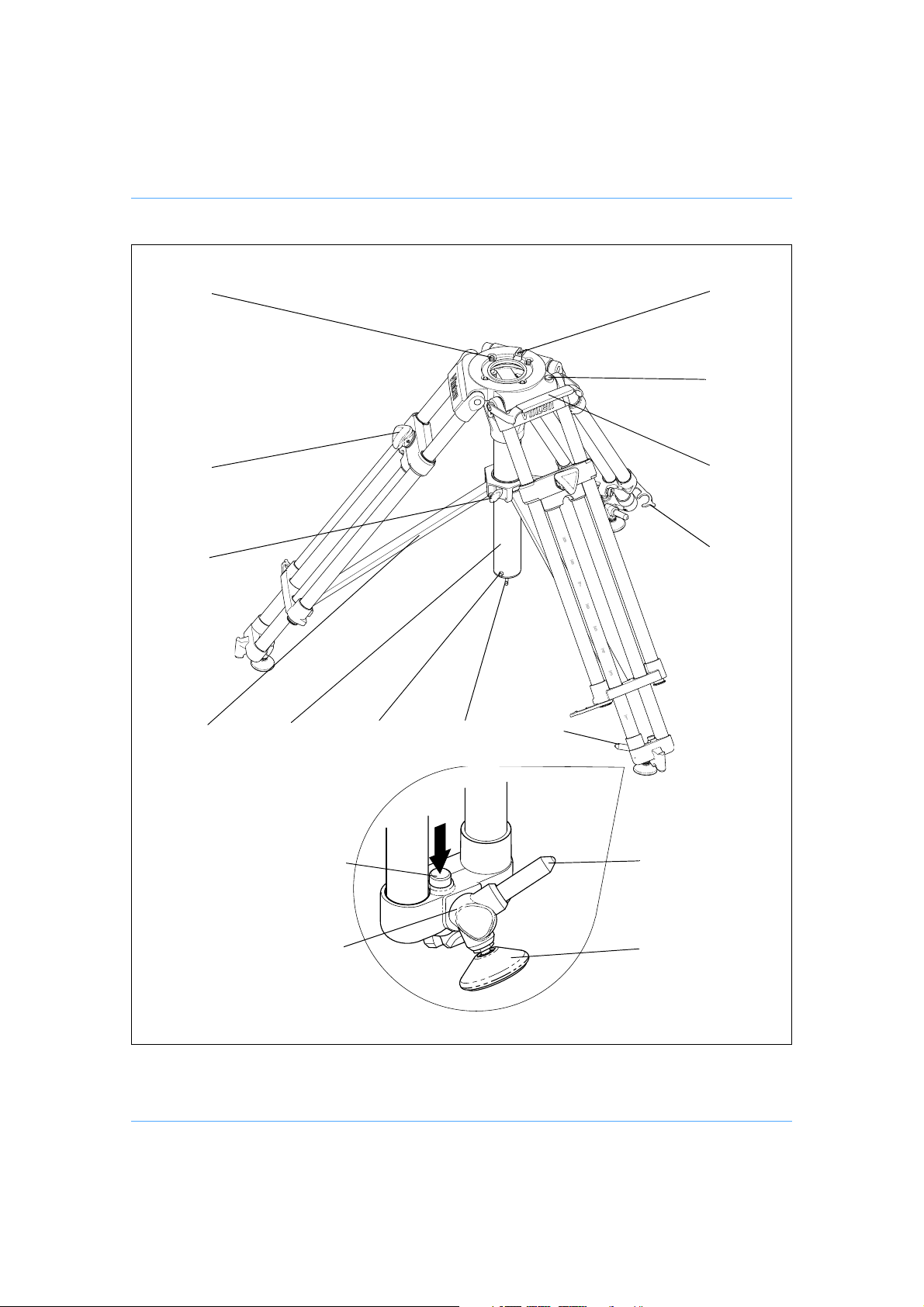
(12)
(1)
(6)
(11)
(10)
(9)
(8)
(7)
(6)
(2)
(3)
(4)
(5)
(5.4)
(5.1)
(5.2)(5.3)
HDT-1 Tripod
7
Page 8

HDT-1 Tripod
(1) Mitchell keyway
(2) Levelling bubble
(3) Carrying handle
(4) Leg retaining clip
(5) Swivel foot assembly
(6) Tie-down hooks
(7) Spreader release button
(8) Spreader support tube
(9) Mid-level spreader
(10) Mid-level spreader clamp
(11) Leg clamp knob
(12) Head mounting bolt
8
Page 9
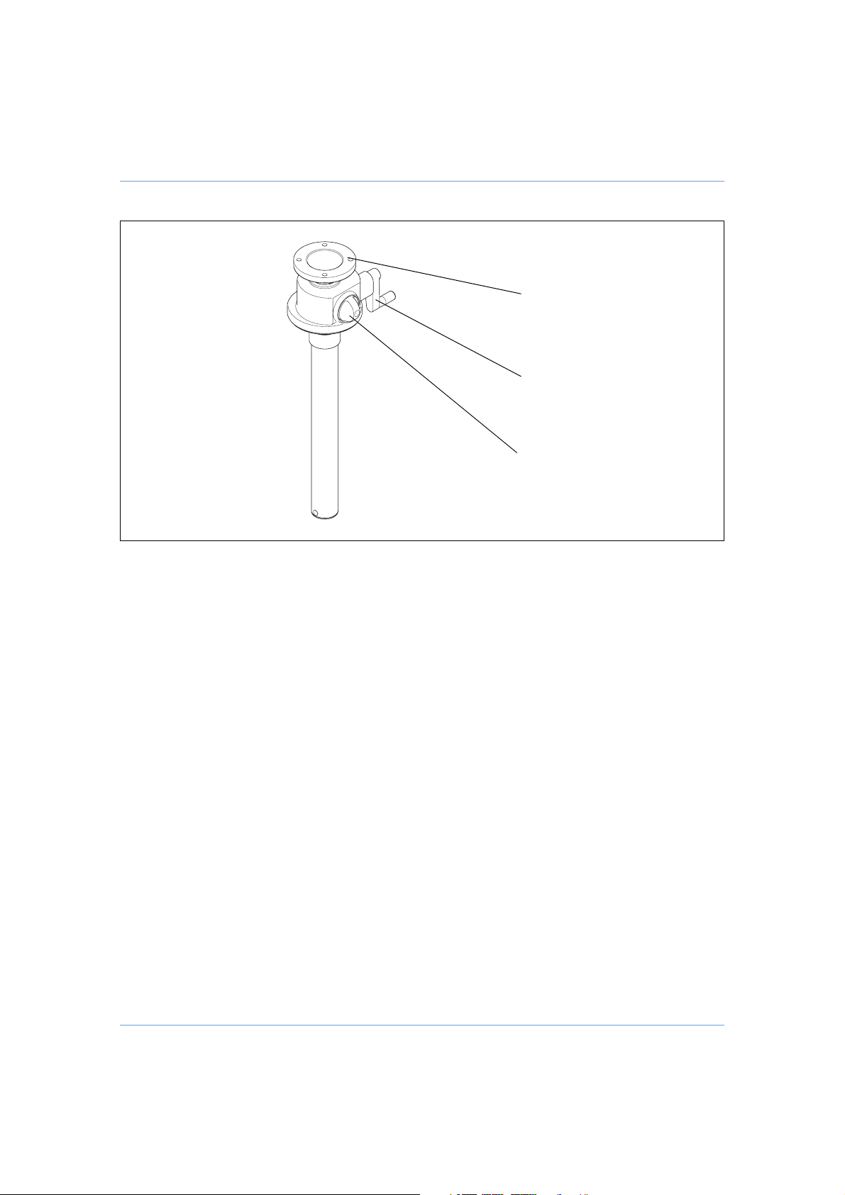
(14)
(15)
(16)
Elevation unit
(14) Four-bolt head fixing
(15) Elevation handle
(16) On-shot clamp
9
Page 10
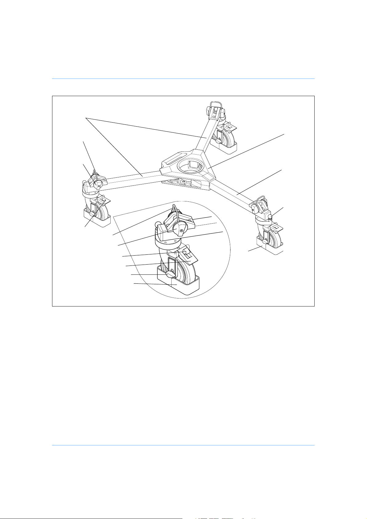
(24)
(23)
(22)
(17)
(18)
(19)
(21)
(23)
(22)
(20)
(21.1)
(21)
(20.1)
(20)
Dolly
(17) Centre casting
(18) Fixed leg
(19) Track lock pin (Studio version only)
(20) Cable guard (Studio version only)
(21) Foot brake
(22) Foot clamp knob
(23) Foot clamp wire
(24) Folding legs
10
Page 11
(30)
(25)
(26)
(29)
(28)
(31)
(27)
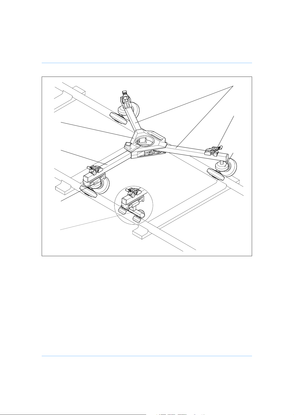
Tracking dolly
(25) Folding legs
(26) Foot securing strap
(27) Twin 12.5 cm wheel assembly
(28) Wheel slide
(29) Fixed leg
(30) Centre casting
(31) Quad 6.2 cm wheel assembly
11
Page 12

Introduction
The Vinten® HDT Heavy-Duty Tripod Range includes single- and two-stage tripods with mid-level
spreaders; OB, studio and tracking dollies and an elevation unit.
Single-stage tripod (HDT-1)
The single-stage tripod has a minimum height of 59 cm (23.2 in.). When used with a floor spreader, maximum height is 123 cm (48.4 in.). Mounted on a dolly, the height range is 86.2 cm to 142.2
cm (34.0 in. to 56.0 in.).
Each leg has a three-position swivel foot assembly (5), which provides a flat foot for studio use or
a spike for use on soft ground. When set to the third position, the foot and spike are turned inwards
for transit or for installation on a dolly or floor spreader. The innovative leg clamps (11) incorporate
a self-limiting mechanism which provides a guaranteed clamping force and prevents overtightening. Graduations on the legs facilitate deployment. Clips (4) on each leg retain the tripod in the
closed position.
A mid-level spreader (9), attached to each leg, is free to slide on the spreader support tube (8).
The spreader is retained on the tube by a spring-loaded release button (7) and locked in position
by a clamp (10).
A fold-away carrying handle (3) is fitted at the top of one leg. Two tie-down hooks (6) provide additional security in adverse conditions. One is positioned under the tripod head, the other at the
base of the spreader support tube.
The pan and tilt head is attached to the tripod using four captive mounting bolts (12) or by a Mitchell-type centre screw. The Vinten Heavy-Duty Quickfix
bubble (2) is provided.
Maximum payload capacity is 140 kg (308 lb).
®
Adaptor may also be used. A levelling
Two-stage tripod (HDT-2)
The two-stage tripod is basically similar to the single-stage tripod, but with two-stage legs. The
minimum height is 51.1 cm (20.1 in.). Maximum height with a floor spreader is 146 cm (57.5 in.).
Mounted on a dolly, the height range is 78.3 cm to 166.3 cm (30.8 in. to 65.5 in.).
Maximum payload capacity of the HDT-2 is 120 kg (275 lb).
Elevation unit
The elevation unit attaches directly to the single-stage tripod and has a height range of 45.8 cm
(18.0 in.). It will support a maximum payload of 113 kg (250 lb). Elevation is achieved by a geared
handle (15) and an on-shot clamp is provided (16).
The elevation unit should not be fitted to the two-stage tripod, as stability is reduced when the elevation unit is fully extended.
The pan and tilt head is attached to the elevation unit with a four-bolt fixing as standard (14), with
provision for Mitchell, Quickfix and 100/150 mm bowl adaptors as options.
12
Page 13

Dolly
The Vinten heavy-duty dolly is designed to provide a steering and castoring base for the two
heavy-duty tripods. It comprises a centre casting with carrying handle (17), a fixed leg (18) and
two folding legs (24). The dolly will support a payload of 160 kg (325 lb). The heavy-duty dolly is
available in studio, outside broadcast (OB) and tracking versions.
Studio
Each leg has a 12.5 cm (5 in.) diameter braked castoring wheel with cable guards (20). A foot support and clamp wire (22) secures each tripod leg to the dolly. Locking pins (19) in each wheel assembly are engaged or disengaged to provide castor, track or steer modes.
OB
Each leg has a 15 cm (6 in.) diameter braked castoring wheel (20). A foot support and clamp wire
(22) secures each tripod leg to the dolly.
Tracking dolly
The heavy-duty tracking dolly is designed for use on standard gauge (62 cm) track. It comprises
a centre casting with carrying handle (30), a fixed leg (29) and two folding legs (25). The dolly will
support a payload of 160 kg (325 lb).
Two versions are available. One has twin 12.5 cm (5 in.) diameter wheels (27) on each leg. The
second has four 6.2 cm (2.4 in.) diameter wheels (31) on each leg, which provide a smoother pas-
sage over track joints.
The axles of the wheels are set at 90° to each other, thus locating the dolly on the track. The wheel
assembly on the fixed leg is free to move in and out on a slide (28), which allows the dolly to negotiate curves in the track.
13
Page 14

Operation
Tripods
Erecting the tripod
Release the leg retaining clips (4), slacken the spreader clamp (10) and spread the legs.
Select the appropriate tripod foot for each leg by pressing the foot release button (5.4) and turning
the swivel foot assembly. Use the spike (5.1) for soft surfaces or the rubber foot (5.2) for hard surfaces. To install the tripod on a floor spreader or dolly, turn the swivel foot assembly to the transit
position (5.3).
NOTE: Unless installing on a dolly or floor spreader, keep the mid-level spreader
For standing height operations using a two-stage tripod, undo the three bottom clamps and extend
the bottom stages fully. Tighten the clamps fully. Unless conditions are extreme (split levels etc)
the bottom stages should be fully extended or fully retracted.
Adjust the operating height by undoing the top clamps and pulling the tripod up to the required
height. Graduations are provided on each leg to facilitate height setting.
Level the tripod head using the level bubble. Tighten the clamps fully.
Tighten the spreader clamp.
In adverse conditions secure the tripod using the tie-down hooks (6), or suspend a weight from a
hook.
attached to the tripod.
Mounting a head
The head is mounted on the tripod with a either a standard Vinten four-bolt mounting or a Mitchell-type centre screw . Additionally , a heavy-duty Quickfix adapto r may be used for heads supplied
with a Quickfix mounting and 100/150 mm bowl adaptors for heads with a ball base (see “Optional
accessories” on page 28).
Vinten four-bolt mounting
Position the head on the tripod and engage the four captive bolts (12) with the head.
Tighten the bolts using a suitable screwdriver or coin, or use a suitable box spanner (16 mm (5/8
in.) AF).
Mitchell-type centre screw
Position the head on the tripod and engage the key in the keyway (1). Insert the clamping ring
from the underside of the tripod and tighten.
Heavy-duty Quickfix adaptor
Position the heavy-duty Quickfix adaptor on the tripod and engage the four captive bolts (12).
14
Page 15

Tighten the bolts using a suitable screwdriver or coin, or use a suitable box spanner (16 mm (5/8
in.) AF).
To mount a head:
Push up the red safety latch and unlock the adaptor by pulling the lever fully outwards and
to the left.
Position the head in the adaptor, ensuring that it seats correctly in the recess and the safety
button is depressed.
Lock the head in the adaptor by pushing the lever fully inwards to the right until the red safety latch operates.
100/150 mm bowl adaptors
Position the bowl adaptor on the tripod and engage the four captive bolts (12) with the adaptor.
Tighten the bolts using a suitable screwdriver or coin, or use a suitable box spanner (16 mm (5/8
in.) AF).
Install the head in the adaptor and secure with the bowl clamp after levelling the head.
15
Page 16

Elevation unit
Installing or removing the elevation unit
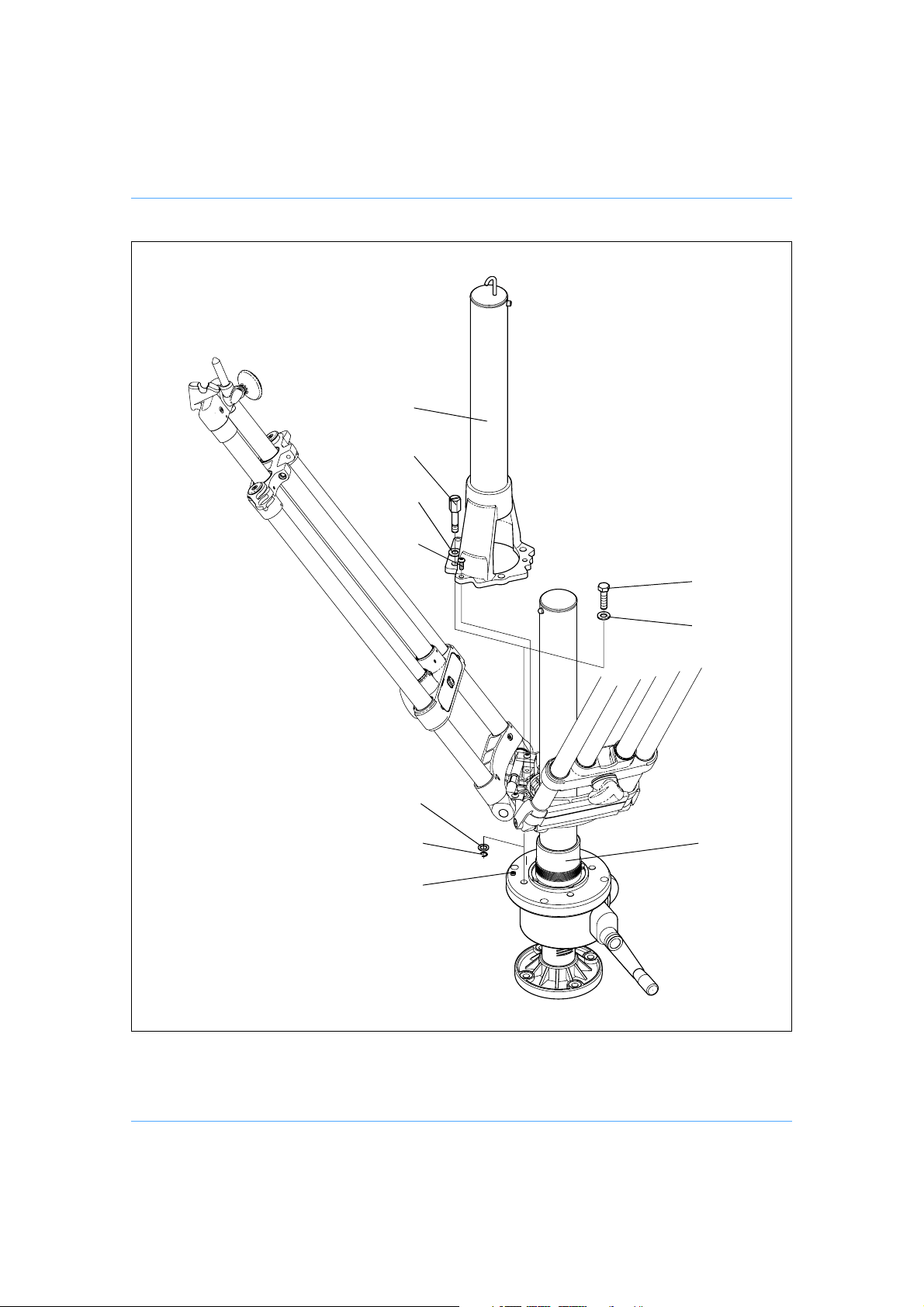
The elevation unit may be fitted to the single-stage tripod. To install the elevation unit it is necessary to remove the four captive head mounting bolts and the spreader support tube.
WARNING! The elevation unit should not be fitted to the two-stage tripod,
To install the elevation unit:
If fitted, remove the mid-level spreader (see “Removing or refitting the mid-level spreader”
on page 21).
Remove circlips (12.3) and washers (12.2) securing four head mounting bolts (12) and
washers (12.1). Retain bolts, washers and circlips for future use.
Remove three screws (8.1) securing the spreader support tube (8) to the underside of the
tripod head.
Position the elevation unit (13) in the tripod so that the locating pin (13.3) on the mounting
flange engages with the Mitchell keyway on the tripod.
Secure the elevation unit using the four 3/8in. bolts (13.1) and washers (13.2) provided.
Unless installing the tripod on a dolly or floor spreader, refit the mid-level spreader.
To remove the elevation unit:
If fitted, remove the mid-level spreader (see “Removing or refitting the mid-level spreader”
on page 21).
Remove the four 3/8in. bolts (13.1) and washers (13.2) securing the elevation unit to the
tripod head.
as stability is reduced when the elevation unit is fully extended
NOTE: The spreader support tube (8) will align with the tripod head in only one
position.
Install the spreader support tube (8) on the underside of the tripod head and secure using
three screws (8.1) and Loctite 221.
Install four head mounting bolts (12) and washers (12.1) and secure with washers (12.2)
and circlips (12.3).
Unless installing the tripod on a dolly or floor spreader, refit the mid-level spreader.
16
Page 17
(8)
(12)
(12.1)
(8.1)
(12.2)
(13.1)
(13.2)
(12.3)
(13.3)
Installing or Removing the Elevation Unit
(13)
17
Page 18

Mounting a head
The head is mounted on the elevation unit with a either a standard Vinten four-bolt mounting, a
Mitchell-type centre screw, Quickfix adaptor or 100/150mm bowl adaptor.
WARNING! Before installing a component on the elevation unit, hold a fix-
ing bolt in position and check that the threaded end is not overlong for that component.
Vinten four-bolt mounting
Position the head on the elevation unit and secure with four bolts.
Mitchell-type centre screw
Secure the Mitchell adaptor to the elevation unit with four bolts.
Position the head on the adaptor and engage the key in the slot. Install the clamping ring and tighten.
Heavy-duty Quickfix adaptor
Secure the heavy-duty Quickfix adaptor to the elevation unit with four bolts.
To mount a head:
Push up the red safety latch and unlock the adaptor by pulling the lever fully outwards and
to the left.
Position the head in the adaptor, ensuring that it seats correctly in the recess and the safety
button is depressed.
Lock the head in the adaptor by pushing the lever fully inwards to the right until the red safety latch operates.
100/150 mm bowl adaptors
Secure the bowl adaptor to the elevation unit with four bolts.
Install the head in the adaptor and secure with the bowl clamp after levelling the head.
18
Page 19

Studio and OB dollies
Assembling the dolly
Turn the dolly upside-down, depress the leg locking plungers and pull each folding leg out until
the plungers lock the legs in the open position.
Set the dolly on the ground on its wheels and apply the wheel brakes.
Brakes
Each of the dolly wheels is fitted with a foot operated brake (21). The brakes are applied by press-
ing down on the lever situated above the wheel and released by pressing down on the centre
`pop-up' lever (21.1) which is raised when the brake is on.
Cable guards - studio version only
The cable guards (20) are height adjustable and should be set as required. Adjustment is carried
out by slackening the knobs (20.1), setting the cable guard at the required height and re-tightening
the knobs.
Dolly movement - studio version only
The wheels on the dolly can be locked in the straight-ahead position or set to castor freely. The
castor/lock changeover is effected by spring-loaded track lock pins (19) on each wheel assembly.
The pins on the folding legs have black knobs and the pin on the fixed leg a red knob. To engage
or disengage a pin, pull it up against the spring and turn through 90°. The pin will only engage with
the wheel when the wheel is properly aligned. This arrangement provides castor, track and steer
motion.
Castor motion
For castor motion, disengage all three track locks. The dolly can now be moved freely in any direction.
Tracking motion
For tracking motion, engage all three track locks. The dolly can now track backwards and forwards
in a straight line.
Steer motion
For steer motion:
Position the dolly so that the fixed leg (with the red knob) is in the direction of travel. Disengage the red track lock.
Engage the black track locks.
With the fixed leg of the dolly facing forwards the dolly can now be moved with a `steering-type' motion.
19
Page 20

Installing a tripod
Release the clamp on the mid-level spreader. Remove the floor spreader, if fitted. Ensure that the
swivel foot assemblies are set to the transit position.
Secure the tripod to the dolly as follows:
Turn the foot clamp knobs (22) away from the dolly centre to raise the foot clamp wires (23).
Spread the tripod legs and engage the feet on the balls of the foot supports. Position the
foot clamp wire over the tripod foot and turn the foot clamp knob (22) towards the dolly centre.
Adjust the operating height by undoing the clamps and pulling the tripod up to the required height.
Tighten the clamps fully. If a two-stage tripod is in use the bottom stage should be fully extended
or fully retracted.
Four-bolt adaptor
A special four-bolt adaptor (Vinten Part No. 3368-24) enables a pan and tilt head (with flat base)
to be mounted directly on the dolly.
Tracking dolly
Assembling the dolly
Turn the dolly upside-down, depress the leg locking plungers and pull each folding leg out until
the plungers lock the legs in the open position.
Set the dolly on the track on its wheels.
NOTE: Ensure that the two folding legs (with fixed wheel assemblies) (25) are on one
track and the fixed leg (with sliding wheel assembly) (29) is on the other. On
curved track, the fixed leg may be on the inside or outside of the curve
Installing a tripod
Install a Vision or heavy-duty tripod on the dolly as follows:
Release the clamps on the mid-level spreader, if fitted. Remove the floor spreader, if fitted.
On heavy-duty tripods, ensure that the swivel foot assemblies are set to the transit position.
Spread the tripod legs and engage the feet on the balls of the foot supports. Secure each
foot with the rubber strap.
Adjust the operating height by undoing the clamps and pulling the tripod up to the required
height. Tighten the clamps.
20
Page 21
Removing or refitting the mid-level spreader
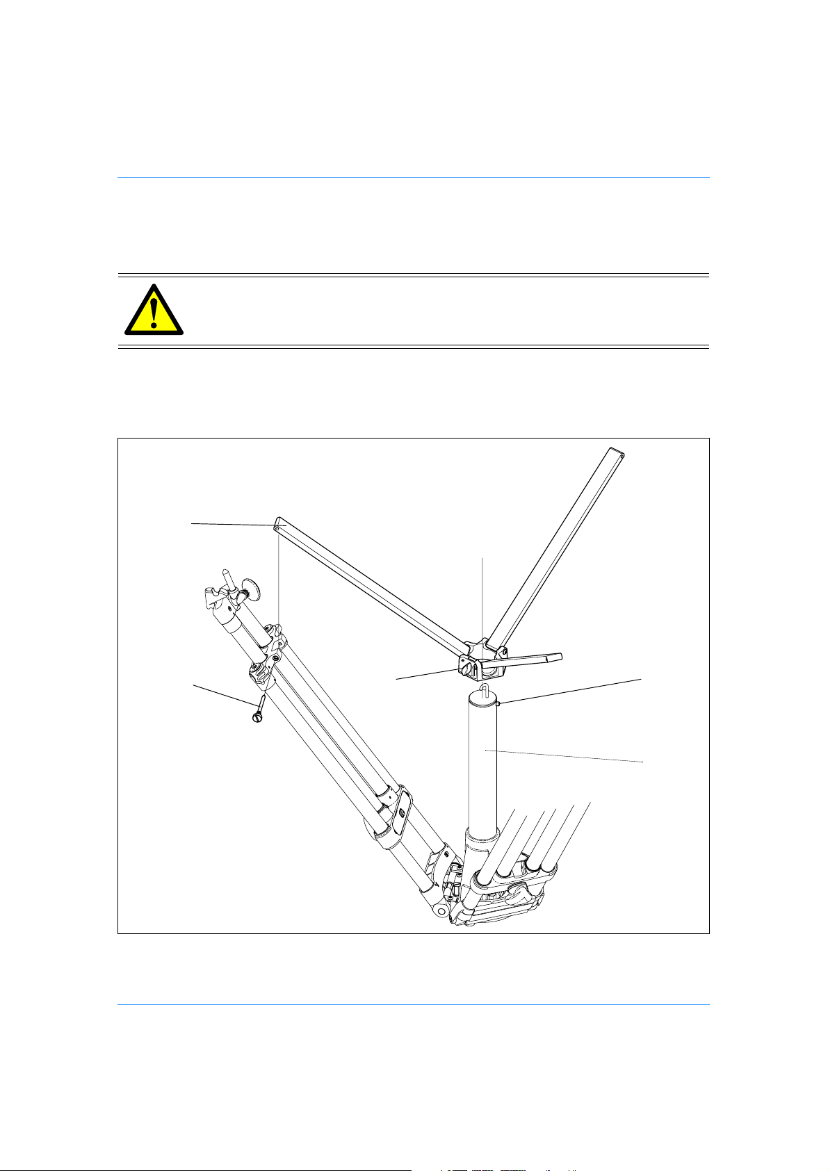
The mid-level spreader may be removed when the tripod is being used with a dolly or floor spreader.
WARNING! Do not use the tripod without the mid-level spreader unless it is
mounted on a dolly or floor spreader.
(9)
(9.1)
(10) (7)
Removing or Refitting the Mid-Level Spreader
(8)
21
Page 22

To remove the mid-level spreader:
Fully slacken the spreader clamp (10).
At each spreader fixing point, unscrew and remove the spreader attachment screw (9.1).
Depress the spreader release button (7) and pull the spreader off the support tube (8).
Refit the spreader attachment screws (9.1).
To refit the spreader:
At each spreader fixing point, unscrew and remove the spreader attachment screw (9.1).
Depress the spreader release button (7) and slide the spreader over the support tube (8).
At each spreader fixing point, position the spreader and screw in the spreader attachment
screw (9.1).
22
Page 23

Servicing
General
Vinten products are robustly made to high engineering standards and little attention is required to
maintain serviceability save regular cleaning. Attention to the following points will ensure a long
and useful service life with minimum need for repair.
Cleaning
During indoor use, the only cleaning required should be a regular wipe over with a lint-free cloth.
Dirt accumulated during storage may be removed using a semi-stiff brush. Particular attention
should be paid to the leg clamps and the tripod mounting face.
Use out-of-doors under adverse conditions will require special attention. Salt spray should be
washed off with fresh water at the earliest opportunity. Sand and dirt acts as an abrasive and
should be removed using a semi-stiff brush or vacuum cleaner.
NOTE: Use only detergent-based cleaners. DO NOT use solvent- or oil-based cleaners,
abrasives or wire brushes to remove accumulations of dirt, as these damage
the protective surfaces.
Clamp sleeves
The leg clamps are fitted with removable clamp sleeves. In the event that sand, d irt or other contaminants have entered the clamp the sleeves may be removed for cleaning, as follows.
NOTE: Figure shows a top clamp. Other leg clamps are of similar construction.
Remove any payload from the tripod.
Release the leg clamp.
Grip the knob (11) and remove the retaining screw (11.3).
Unscrew the knob (11) until the clamp plate (11.2) and spherical clamp nut (11.4) can be
removed from the clamp housing (11.5).
Rotate the clamp sleeves (11.6) inwards so that the lugs on the sleeves line up with the cut-
outs in the clamp housing (11.5).
Slide the clamp sleeves up the tripod legs until they are clear of the clamp housing.
Using a semi-stiff brush or vacuum cleaner, remove any dirt from the faces of the clamp
sleeves and the inside of the clamp housing.
WARNING! Do not attempt to remove the clamp sleeves from the tripod
legs. If a clamp sleeve is damaged it should be replaced by qualified personnel in accordance with the Maintenance Manual
(Publication Part No. 3901-9).
23
Page 24
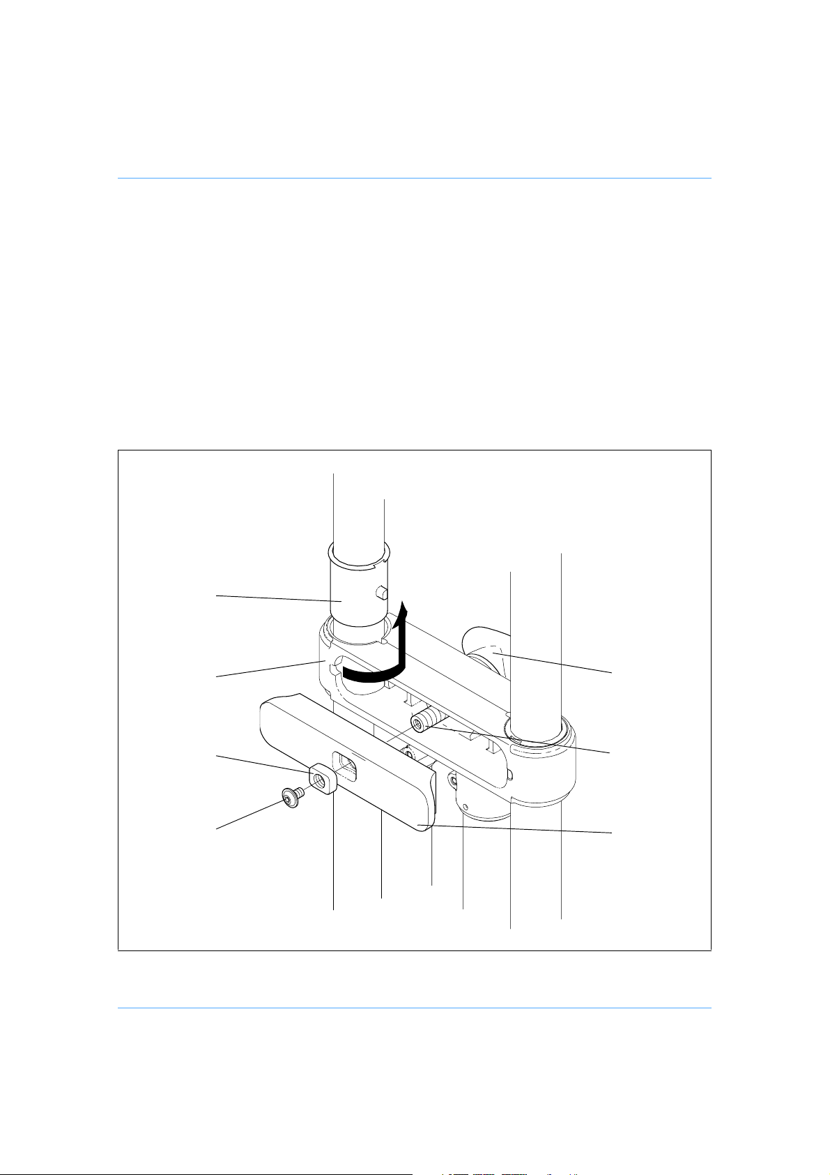
Refit the clamp sleeves by aligning the lugs on the sleeves (11.6) with the cut-outs in the
clamp housing (11.5) and sliding them down the legs.
Rotate the clamp sleeves outwards so that the lugs on the sleeves locate in the cut-outs in
the clamp housing.
Position the clamp plate (11.2) in the clamp housing (11.5), ensuring the lugs on the clamp
sleeves (11.6) are correctly located.
Position the spherical clamp nut (11.4) in the clamp plate (11.2), ensuring that the curved
face of the nut is towards the clamp plate.
Screw the knob (11) into the spherical clamp nut (11.4) until the clamp is finger-tight.
Fit the retaining screw (11.3).
(11.6)
(11.5)
(11.4)
(11.3)
(11)
(11.1)
(11.2)
Clamp Sleeves
24
Page 25
Routine maintenance
Tripods
During use, check for ageing and cracking of the rubber foot securing straps on the floor spreader
(if used) and renew if necessary.
No further routine maintenance, other than regular cleaning, is necessary on the tripods. The
clamps should never require adjustment.
Elevation unit
During use, check the effectiveness of the on-shot clamp and adjust if necessary.
No further routine maintenance, other than regular cleaning, is necessary on the elevation unit.
Dollies
During use, check for ageing and cracking of the rubber foot securing straps and renew if necessary.
On studio dollies, check the tracking.
No further routine maintenance, other than regular cleaning, is necessary on the dolly.
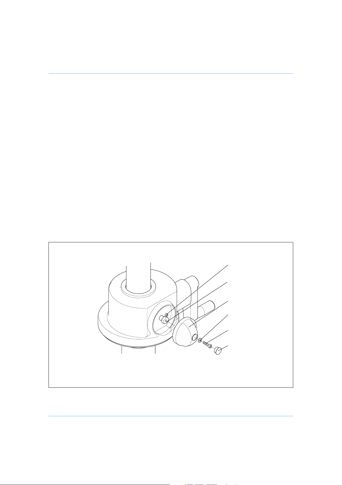
Elevation Unit On-Shot Clamp
(16.1)
(16.2)
(16)
(16.3)
(16.4)
(16.5)
25
Page 26
Adjustments
Elevation unit on-shot clamp
After considerable use the on-shot clamp may require adjustment. If the rotation between the ‘off'
stop and the fully ‘on' position exceeds 120°, adjust the clamp as follows:
Remove the hole plug (16.5). Remove the screw (16.4) and washer (16.3) securing knob
(16) to lock spindle (16.2). Remove the knob.
Turn spindle clockwise to fully tighten clamp, then turn counter-clockwise 120° (two flats).
Position knob on spindle so that it is against the stop screw (16.1). Ensure that rotation to
fully ‘on' is less than 120° and that the clamp is fully ‘off' when against the stop screw. Remove knob and rotate spindle until this is achieved.
Secure knob with screw (16.4) and washer (16.3), using Loctite 222E. Refit hole plug
(16.5).
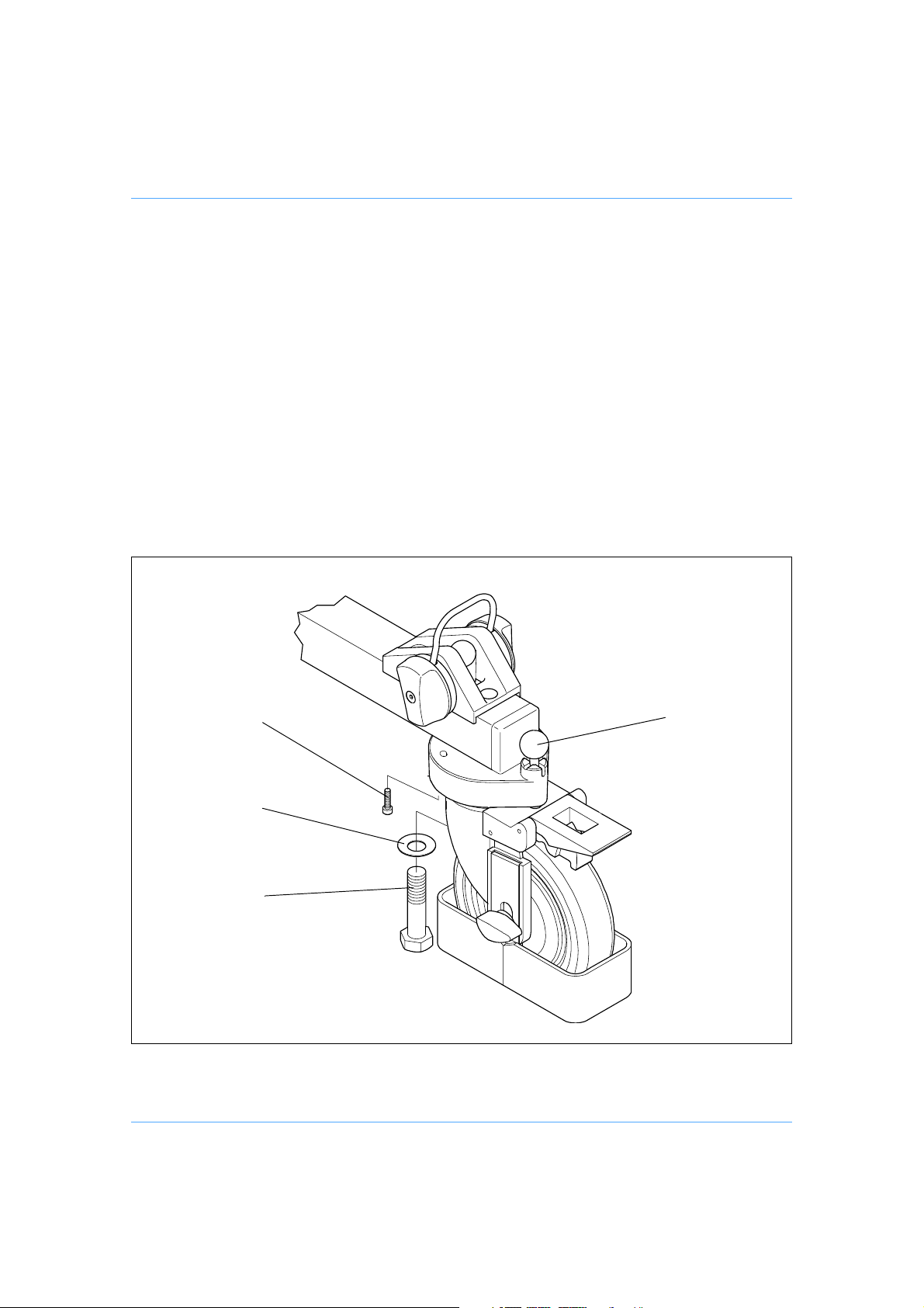
(19.2)
(19.1)
(19)(19.3)
Studio Dolly Tracking
26
Page 27

Studio dolly tracking
Adjustments to the tracking of studio dollies may become necessary after considerable use.
Check the tracking as follows:
With the track locks engaged and a payload fitted, the dolly should track in a straight line
over a distance of 3.6 m (12 feet) with deviation not exceeding 5 cm (2 in.). If this cannot
be achieved, the wheels should be re-aligned. When re-aligning the wheels, start by adjusting the wheel with the red locking knob on the fixed leg. This will often correct any alignment
problems.
To re-align the dolly wheels:
Remove the tripod from the dolly.
Slacken screw (19.3).
Remove the bolt (19.1) and washer (19.2) securing the castor to the fixed leg. Apply Loctite
270 to the bolt and refit bolt and washer and tighten lightly.
Engage the track lock (19) on each castor.
Align the wheel on the fixed leg so that it runs parallel to the leg.
Using a suitable straight line on the studio floor, check that over a distance of 3.6 m (12 feet)
the deviation does not exceed 5 cm (2 in.). Re-adjust the wheel until this is achieved. If it
cannot be achieved, the wheels on the other two legs should be re-aligned.
Once the wheels have been correctly aligned, tighten bolts (19.1) and screws (19.3).
27
Page 28

Parts list
The following lists include main assemblies and optional accessories. For further information regarding repair or spare parts, please contact Vinten Broadcast Ltd or your local distributor.
For information on-line, visit our website at
www.vinten.com.
Main assemblies
HDT-1 single-stage tripod 3901-3
HDT-2 two-stage tripod 3902-3
Elevation unit 3370-3
OB dolly 3497-3B
Studio dolly 3497-3C
Tracking dolly (black), 12.5 cm twin wheels 3369-51
Tracking dolly (black), 6.2 cm quad wheels 3369-57
Mid-level spreader for single-stage tripod 3901-25
Mid-level spreader for two-stage tripod 3902-25
Optional accessories
Heavy-duty QuickFix adaptor 3490-3
100 mm levelling bowl adaptor 3330-16
150 mm levelling bowl adaptor 3330-17
Four-bolt adaptor 3368-24
Floor spreader 3367-3
Spanner - for head fixing bolts J551-001
28
 Loading...