

Vintec ESPACE3000-KIT, ESPACE1000-KIT, ESPACE1500-KIT, ESPACE2000-KIT, ESPACE2500-KIT User Manual
...Page 1
User Manual
Espace Walk-in Cellar
vintec.com
ESPACE1000-KIT
ESPACE1500-KIT
ESPACE2000-KIT
ESPACE2500-KIT
ESPACE3000-KIT
ESPACE3500-KIT
ESPACE4000-KIT
ESPACE1000-EXT
Page 2

Welcome
Safety
Thank you for your purchase of a Vintec product.
We take particular care in manufacturing our
products in terms of their design, ergonomics and
ease of use. We hope that you will be completely
satised with this product.
This wine cellar, together with its conditioning unit, is not
intended for use by persons (including children) with reduced
physical, sensory or mental capabilities, or lack of experience
and knowledge, unless they have been given supervision
or instruction concerning use of the appliance by a person
responsible for their safety. Children should be supervised to
ensure that they do not play inside the cellar or with any of
its components.
GENERAL WARNINGS:
• Do not use electrical appliances inside the cellar,
unless they have been recommended in writing by
the manufacturer.
• Do not store explosive substances inside the cellar
appliance such as aerosols containing ammable
propellant gas.
R404A REFRIGERANT WARNING:
This appliance contains R404a refrigerant. Avoid safety
hazards by carefully installing, handling, servicing and
disposing of this appliance.
• Ensure that the tubing of the refrigerant circuit is not
damaged during transportation and installation.
• The room for installing appliance must be at least 1m
per 8g of refrigerant. The amount of refrigerant charged
in the appliance can be found on the rating plate on the
appliance.
3
• Keep ventilation openings in the appliance enclosure,
or in the built-in structure, clear of obstruction.
Important information that may impact your Manufacturer’s Warranty
Adherence to the directions for use in this manual is extremely important for health and safety.
Failure to strictly adhere to the requirements in this manual may result in personal injury,
property damage and affect your ability to make a claim under the Vintec manufacturer’s
warranty provided with your product. Products must be used, installed and operated in
accordance with this manual. You may not be able to claim on the Vintec manufacturer’s
warranty in the event that your product fault is due to failure to adhere to this manual.
User Manual Espace Walk-in Cellar1
Page 3

Contents
Description of your wine cellar 3
Cellar 3
Conditioner 3
Power supply 4
Caring for the environment and saving energy 4
Installing your cellar 5
Dimensions 5
Preparation for installation 6
Components list 8
Assembly procedure 11
Technical specications 17
Maintenance 17
Loading and storing your wine 18
Setting your cellar's temperature 19
Notes 20
Warranty 22
Standard wine serving temperatures (°C)
French
Alsace 10°
Beaujolais 13°
Sweet white Bordeaux 6°
Dry white Bordeaux 8°
Bordeaux reds 17°
Burgundy whites 11°
Burgundy reds 14°
Champagne 6°
Jura 10°
Languedoc-Roussillon 13°
Provence Rosé 12°
Savoie 9°
Dry white Loire wines 13°
Sweet white Loire wines 7°
Loire reds 14°
Rhône wines 15°
Sweet wines from the South-West 7°
Reds from the South-West 15°
Sauternes 10°
Australian
Cabernet franc 16°
Cabernet sauvignon 17°
Chardonnay 10°
Merlot 17°
Muscat à petit grain 6°
Pinot noir 15°
Sauvignon blanc 8°
Semillon 8°
Shiraz 18°
Verdelho 7°
Other
Californian 16°
Chilean 15°
Spanish 17°
Italian 16°
For more information, visit vintecclub.com/best-temp
User Manual Espace Walk-in Cellar 2
Page 4
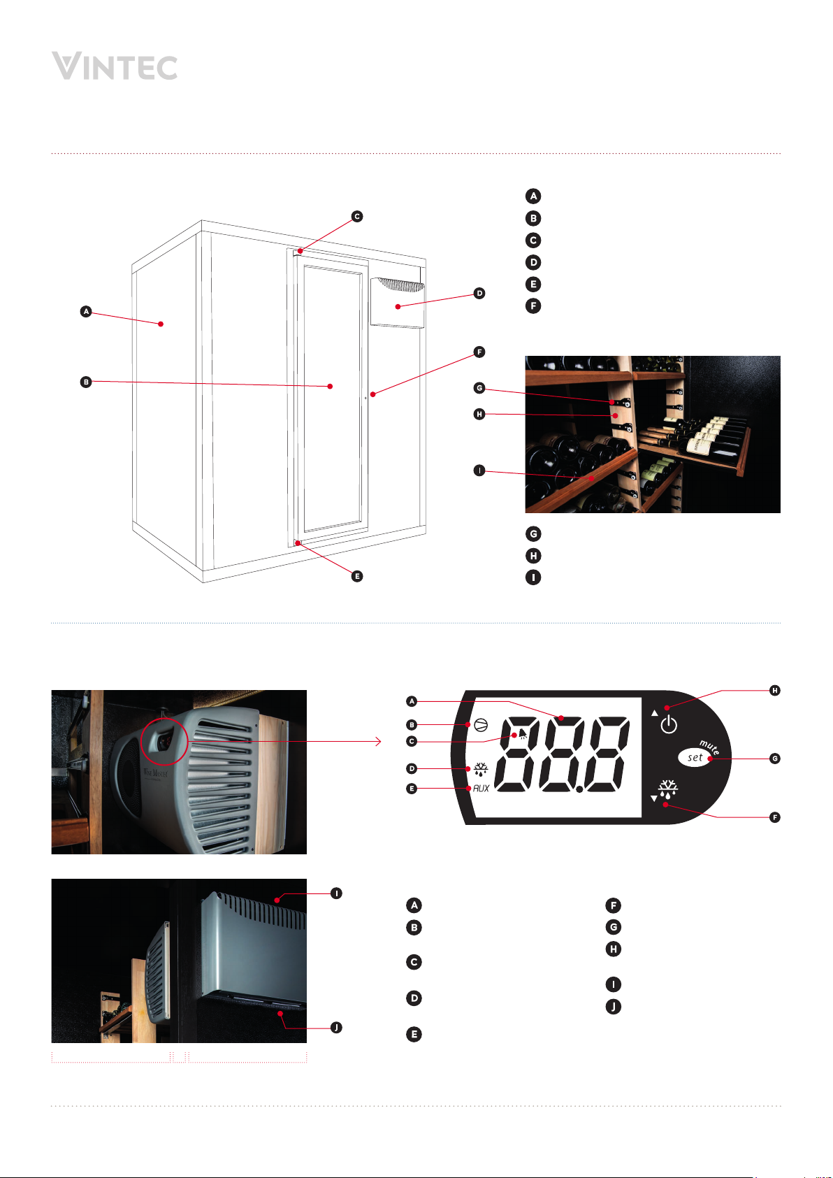
Description of your wine cellar
Cellar
Exterior
Body
Door
Upper hinge
Conditioner unit
Lower hinge
Lock
Interior
Shelf runners
Vertical shelving supports
Shelves
Conditioner
Temperature display
Compressor operation
indicator
Abnormal temperature
alarm
Defrost cycle operation
indicator
Heater operation indicator
Decrease temperature
Set / mute
Standby / increase
temperature
Exhaust air outlet
Air intake
Interior Door
frame
Exterior
User Manual Espace Walk-in Cellar3
Page 5
Power supply
WARNING: For your personal safety, the wine cellar must
be correctly earthed. Ensure that the socket is correctly
earthed and that your installation is protected by a circuit
breaker (30mA residual current device).
In future, if you move the cellar to a foreign country, check that
the power supply characteristics of the conditioner correspond
to the destination country (voltage, frequency) – consult a local
electrician in that country for advice.
Caring for the environment and saving energy
Disposal of packaging
All packaging used by Vintec is made
from recyclable materials.
After unpacking your cellar, take the
packaging to a refuse collection point.
For the most part, it will be recycled.
Recycling: a caring gesture
Electrical and electronic equipment can have a harmful
effect on the environment and human health owing to the
presence of hazard ous substances. Therefore, you should
never trash electronic and electrical equipment with
unsorted municipal waste.
In compliance with legislation relating to protecting and
caring for the environment, your wine cellar does not use
CFCs.
To save energy
• Install your wine cellar in a suitable location
(see 'Installing your cellar') and observe the
recommended temperature ranges.
• Keep the door open for as short a time as possible.
• Ensure that the door seal is in good working order
and that it is not damaged. If it is, contact your
Vintec retailer.
• Disable any unusable appliances by unplugging them
and cutting off the power lead.
User Manual Espace Walk-in Cellar 4
Page 6
Installing your cellar
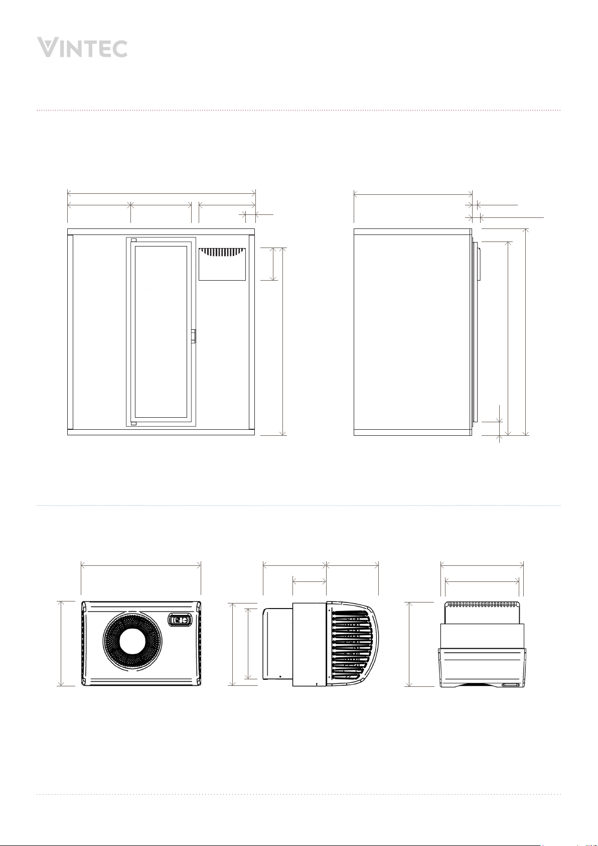
Cellar dimensions
629 598 554
90
320
1860
11701870
53 (door)
85 (conditioner)
2050
1909
FRONT VIEW
Conditioner dimensions
540 286 514238
381
133
SIDE VIEW
150 462
320
374
524
INTERIOR VIEW
NOTE: Illustrations not to scale.
All dimensions in millimetres.
SIDE VIEW TOP VIEW
User Manual Espace Walk-in Cellar5
Page 7
Installing your cellar (cont'd)
Preparation for installation
CRITICAL WARNINGS:
• LOCATION FLOOR LOAD: This walk in cellar and
its contents are EXTREMELY heavy. It is vital that the
oor where it will be located is level and strong enough
to handle the load. For example, the Espace1000
base unit weighs 310kg installed, but loading in 1000
standard wine bottles adds a further static load of
approximately 1500kg. Each 500 bottle extension kit
weighs a further 150kg plus the extra wine weight
(~1.5kg per average bottle). if you are not certain of
the oor load capacity at the planned location We
recommend consulting an architect or structural
engineer to assess its strength before receiving
delivery or commencing assembly of your cellar.
• DELIVERY: Espace cellars are supplied at-packed in
solid wooden crates that weigh up to 400kg in total
(espace1000-kit) or a minimum of 150kg (espace1000ext). Due to the crates’ weight and size, careful
consideration should be given to site accessibility, as
well as the safe lifting capacity of any equipment being
used to transport and manoeuvre the crates.
• ASSEMBLY: The cellar should be assembled in the
same room or space as its nal permanent location,
because once constructed it will be too wide to move
through a standard door opening.
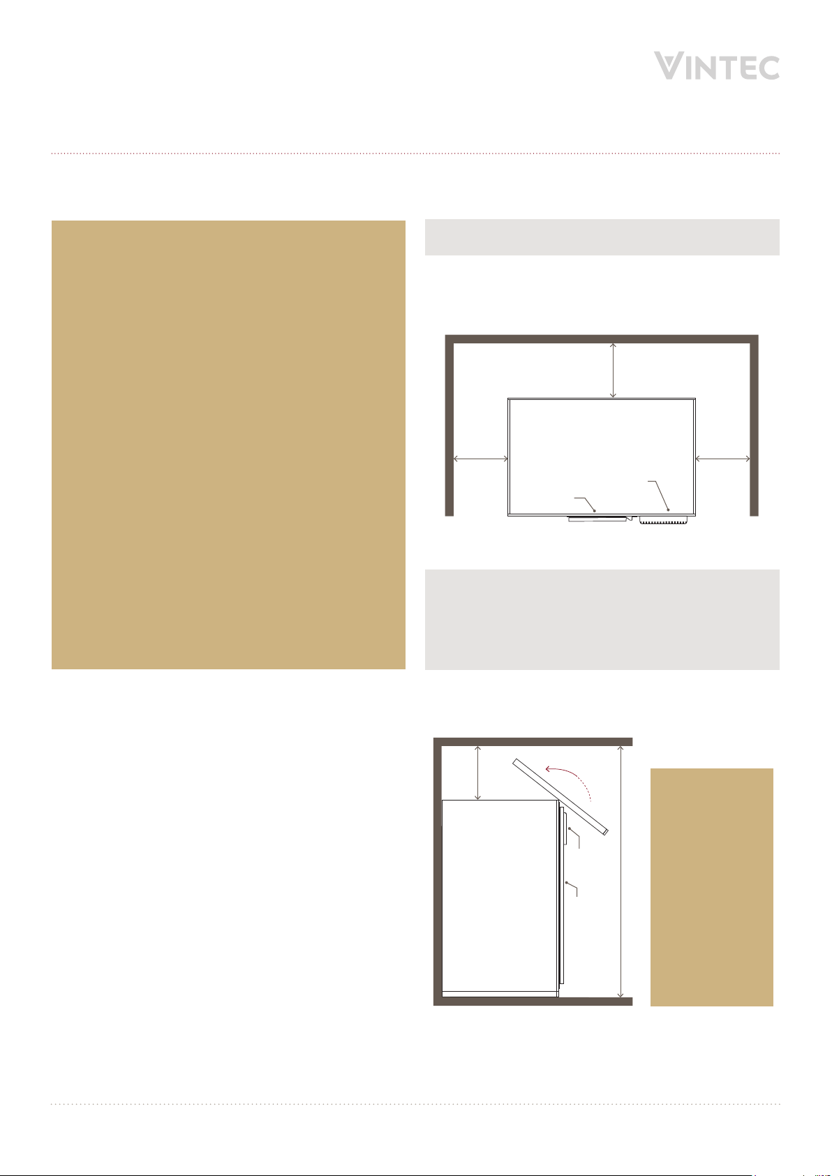
IMPORTANT CONSIDERATIONS:
• Space for assembly: Allow ample room for assembly
of the cellar’s walls. The gap should be big enough to
allow the walls to be screwed together and for you to
move around it easily during assembly (see below).
500 min.
500 min. 500 min.
Conditioner
Door
TOP VIEW
NOTE: Once assembled, you can install the cellar into
a space with less or no space at the sides and back, as
long as you are able to move the cellar into that space
once assembled (will not t through a standard doorway).
See warning below regarding roof access.
Also allow enough clearance from the ceiling to lift and
t the roof of the cellar during assembly (see below).
500 min.
WARNING:
Once assembled
and installed,
you should
Conditioner
Door
ideally ensure
there is still
enough room
2500 min.
to allow access
to the electrical
power lead outlet
on the roof
(for more info
see 'Power' on
page 7).
SIDE VIEW
User Manual Espace Walk-in Cellar 6
Page 8

Installing your cellar (cont'd)
• Direct sunlight/heat: The cellar (particularly the
conditioning unit) must never receive prolonged exposure
to direct sunlight or similar sources of intense heat.
• Ventilation: The external vents of the conditioning unit
must always have access to free owing cool air from
the underside (min 0°C, max 35°C ambient), and an
unobstructed passage for hot air to escape from the top
into a large space that will allow for heat dissipation (for
example a living room).
• Flooring: If the cellar is being installed during
construction or renovation, it is recommended that
installation is completed prior to laying any ooring
material that might be damaged, such as timber or carpet.
• Power: Should service ever be required, access to switch
off, disconnect and reconnect the power cable needs to be
possible. A normal install of this unit includes running the
conditioner power cable through the pre-cut access hole
(sealed with grommets during operation) located in the
roof of the cellar, immediately above the conditioning unit:
procedure’ on page 12. The cellar door itself is not
suitable for full integration or mounting behind cabinetry.
• Position of conditioner unit: Due to the interlocking
design of the wall panels, the conditioning unit can only
be installed next to the door on the front right side of
the cellar (when viewed from outside).
• Excess humidity/moisture removal: The conditioning
unit has an excess moisture run-off tube coming from
the underside of the conditioning unit (inside the cellar).
This must either be fed into a collection vessel (such as
an empty Champagne bottle) that is monitored/emptied
manually, or alternatively plumbed into your household
mains via gravity feed for automatic removal.
Mains plumbing is recommended for higher humidity
or tropical areas such as northern Queensland or the
Northern Territory.
If this is not possible, please ask a licensed and qualied
electrician to install a weatherproof power point inside
the cellar to provide power for the conditioner:
NOTE: Alternatively, hinged cabinetry is an ideal
aesthetic and functional solution to maintain access
to the cellar’s roof.
• Cellar door: The cellar door can be installed left or right
hand hinged – see warning after step 10 in the ‘Assembly
• Noise: The compressor on the conditioner unit works
24 hours a day, and makes a light humming sound,
similar to that of an air conditioning unit.
Other considerations:
• Filters: The conditioning unit has a lter which must be
periodically cleaned. This is accessed from the underside
of the conditioning unit, on the outside of the cellar.
Failure to maintain this lter may compromise cellar
efciency, performance and warranty.
• Lighting: The cellar is supplied with individual battery
operated LED downlights. If you choose to install
aftermarket or custom lighting solutions, we suggest the
use of LED lights with low UV and heat characteristics,
plus the use of timers or motion sensors to remove the
risk of lights being left on for long periods as this may
affect your wine.
• Conditioner unit nish: In addition to the ability to install
your own cabinetry in front of and around the majority of
the unit, you may choose to spray paint the outer housing of
the conditioning unit to match the colour of your cabinetry
or surrounding material. Please ensure that this outer
housing is removed from the working mechanisms of the
conditioning unit prior to any spray coatings being applied.
User Manual Espace Walk-in Cellar7
Page 9

Installing your cellar (cont'd)
Components list
CELLAR COMPONENTS
User Manual Espace Walk-in Cellar 8
Page 10

Installing your cellar (cont'd)
ASSEMBLY COMPONENTS
A1
A2
A3
A4
A5
A6
A7
A8
User Manual Espace Walk-in Cellar9
Page 11

Installing your cellar (cont'd)
CONDITIONER COMPONENTS
C1
C2
C3
C4
C5
C6
SHELVING COMPONENTS
S1
S2
S3
S4
S5
Exterior Door
frame
Interior
S6
User Manual Espace Walk-in Cellar 10
Page 12

Installing your cellar (cont'd)
Assembly procedure
NOTE: This information is for assembly of the standard
Espace 1000 kit (ESPACE1000-KIT) without any
extensions. If extension modules (ESPACE1000-EXT)
are also being added, they must be inserted between
the front and rear panels of the standard kit – see
‘Adding extension modules’ on page 16 for additional
instructions.
Although the cellar kit can be assembled by one person only,
it is strongly advisable that at least two people work together
to complete it.
Before commencing assembly of the kit, make the following
preparations:
• Arrange the cellar panels in numerical order.
• Pull back the white protective plastic wrap from the
corners/edges of the cellar panels by an inch or two to
make sure that any unsightly bits of plastic do not get
caught in the corners during assembly (the plastic should
be mostly left on until the body is completely assembled
to minimise risk of scratching.
Exterior body assembly
1 Arrange the two oor panels and on a at, level
surface, leaving enough space around to be able to
assemble the walls later. Check that the surface is clean
and will not scratch the panels – consider laying down a
protective sheet rst. The oor panels should initially be
laid upside down, so that the timber support slats
are facing up.
2 Insert one of the short joining strips
the inside edge of panel
marrying the joining strip into the corresponding slot in
panel
and pushing them rmly together.
, then connect the panels by
into the slot on
• Read through the entire assembly procedure.
• Unwrap the various accessories and tools and
familiarise yourself with them.
• Prepare a manual Philips head screwdriver or a cordless
drill with a Philips head driver, a roll of removable adhesive
tape, and a small step ladder to enable access to the
cellar's roof once assembled.
• Unscrew whichever of the door hinges will become the
upper hinge (see warning note after step 10) and
dismount the door, which will be replaced at the very
end of assembly.
• One tube of silicone is supplied with your Espace1000
unit, but you may wish to have a second one on hand in
case the rst one is exhausted during the sealing process.
Ideally it should be black in colour and suitable for a
high moisture environment.
3 Secure panels and together through the metal
frame with
screwdriver or a cordless drill with a Philips head driver.
4 Once secured, turn the entire oor over so the support
slats are facing down. Ensure that the cellar oor is now
as stable, even and level as possible – this will make the
rest of the assembly much easier and more accurate.
screws using a Philips head manual
User Manual Espace Walk-in Cellar11
Page 13

Installing your cellar (cont'd)
5 Stand left side panel and small back left panel
upright in their positions at the rear left corner of the
oor (when viewed from the front). Slot them down into
the oor grooves (taking care not to damage the panel
surfaces) and nest their edges together so the metal
angle frame wraps over the exterior (see below).
6 Secure panels and to each other temporarily with
the removable adhesive tape. This forms the rst corner
of the cellar.
7 Insert a long joining strip
edge of panel
it marrys against the joining strip and also slots down
into the oor groove (see below).
then position left side panel so that
into the slot on the vertical
9 Position right side panel
the rear right corner of the cellar, and secure the corner
with adhesive tape (see below).
10 Slot front left panel into its groove on the front left
edge of the oor, and temporarily tape it to left side
panel
(see below).
nested against to form
8 Repeat step 7 to connect large back right panel to
panel
with an strip. If necessary, secure panels
and with adhesive tape (see below).
WARNING: Before proceeding to step 11, rst decide
which way you need the door to hinge/open. The door
can be either left or right hinged, but the frame panel
it attaches to must match the chosen hinge direction
– rotate the door frame
to your chosen hinge position before inserting into
place, while still paying attention to the ‘inside’/’outside’
markings.
11 Start assembly of the door section in its position by rst
slotting the door frame bottom block
middle edge of the oor. Next place the door frame
top of the bottom block (see warning above), and nally
cap the door frame with the door top block
necessary (see below).
by 180° in either direction
into the front
on
. Tape if
User Manual Espace Walk-in Cellar 12
Page 14

Installing your cellar (cont'd)
12 Complete the front side of the cellar by slotting the front
right (conditioner) panel
the oor. Tape if necessary (see below).
13 Insert an joining strip into the slot on the vertical
edge of panel
that it not only marrys against the joining strip and slots
down into the oor groove, but also nests its metal angle
frame around front right panel
with adhesive tape (see below). This completes the
walls of the cellar.
then position right side panel
into the front right edge of
so
. Secure the corner
17 Ensure that all other panels are also rmly pressed
together tightly so that no space is left between any
joins and no foam insulation is visible at any seam.
18 Use
19 Apply silicone sealant to all internal panel seams
screws to attach all panels together, screwing
through the holes in the angled metal frame brackets.
Start around the edges of the oor, then work around
the roof, then nally the vertical corner brackets of the
walls (see below).
and smooth to a neat nish (see below). Allow to set
before installing the conditioner unit and shelving.
14 Use a short joining strip to connect the two roof
panels
15 Secure panels
frame with
16 Once
of the walls and position carefully until the angled metal
frame drops down snugly over all four sides. Walk inside
the cellar and inspect the ceiling seams on all sides to
ensure a snug t with minimal gaps. If gaps are visible,
carefully adjust the sides and apply pressure to the roof
to ensure it is pressed down rmly (see below).
and .
and
and together through the metal
screws
are connected, lift the roof up on top
Conditioner unit installation
20 Prepare the conditioner unit for installation by rst
separating it from its timber frame
removing the rear grill cover
21 Note the four pre-drilled bolt holes on the interior of
wall panel
and two below.
22 Temporarily position one of the black metal angle brackets
above the cutout so that its top holes line up with the
bolt holes on wall panel, and partially screw in two of the
bolts (see warning below). The washers can be left
off for now.
– two above the conditioner cutout void
, as well as
(see below).
User Manual Espace Walk-in Cellar13
Page 15

Installing your cellar (cont'd)
WARNING: Each of the pre-drilled bolt holes in the wall
panel have a captive nut secured inside them, which will
receive the
DO NOT use an impact drill or a drill with a high clutch/
torque setting to drive in the bolts – this will break the
adhesive that holds the nut in place and dislodge it,
making it impossible to secure the bolts. Insertion of
the bolts should be started by hand to ensure they are
aligned correctly and not cross-threaded, and then can
be carefully completed using either a manual socket
wrench or a drill on a low clutch/torque setting.
23 Do the same for the bottom metal bracket (note that the
brackets face in opposite directions).
24 Temporarily position the timber frame between the two
brackets, ensuring that its inner edges align with the
edges of the wall panel cutout (see below).
25 Using a pencil, mark the position of the
screw holes on the top and bottom of the timber frame.
26 Remove the timber frame from the wall panel, as well as
carefully removing the bolts and brackets.
27 Use
onto the timber frame using your pencil marks as a
position guide. Do the same for the bottom metal bracket.
28 Insert the main conditioner unit
frame (ensuring that the foam shock absorber strip is on
the lower side), and rest the conditioner onto the foam strip.
29 Use
the timber frame
the conditioner through its metal edge ange and into
the timber frame (see below).
bolts that attach the conditioner unit.
metal brackets’
screws to securely attach the top metal bracket
through the timber
screws to securely attach the conditioner to
by screwing from the rear side of
30 Prepare the condensation water hose connection on
the base of the conditioner unit by removing the plastic
shroud over the hose connector outlet.
31 Connect the condensation hose
connector outlet, and secure it using the spring clamp.
32 Feed the ends of the condensation hose and the power
cable through their outlet holes in the rear grill cover
(see below) and re-attach the grill cover to the body of
the conditioner unit.
33 Lift the conditioner/frame assembly into position and
attach it to wall panel
bolts (including the wide washers this time) through
the metal brackets (see warning after step 22 above).
34 Feed the power lead out through the pre-cut hole in the
roof panel, ready for connection to mains power.
35 Standing inside the cellar, take one half of the plastic hole
cover grommet
lead via the grommet’s pre-cut slit so that the power lead
runs up through the centre of the grommet, then slide the
grommet up to the ceiling and press it into the roof hole
so that it forms a tight seal.
36 From outside the cellar, use a step ladder to access the
roof and repeat step 35 by attaching the other half of the
grommet to the power lead, then slide it down and press
it rmly into the roof hole to seal it.
by carefully re-inserting the two
and ease it sideways onto the power
by sliding it onto the
Interior shelving assembly
37 Sort and arrange the various vertical timber shelving
support frames. Those with shelf runners only on one side
–
– should be installed at the front and back of the
cellar. Those with runners on both sides –
installed in the centre. Take care to ensure the supports
are facing in the correct direction (front to back, and top
to bottom) so that shelves can slide onto their runners
correctly (see below for reference).
– should be
User Manual Espace Walk-in Cellar 14
Page 16

Installing your cellar (cont'd)
NOTE: The shorter support frame must be installed
in the front right corner of the cellar, underneath the
conditioner unit (see below).
Shorter vertical support to
allow space for conditioner unit
38 Sort and arrange the two types of metal cross-bars.
Those with pre-drilled holes –
walls and the oor. Those without holes –
– are for attaching to
– are for
lateral bracing between the vertical support frames.
39 Begin assembly by positioning the rst
single-sided
support frame in the front left corner of the cellar. Using
screws, attach it to the inside face of front wall panel
by screwing through the larger pre-drilled holes in
the timber of the support frame and into the wall panel.
40 Loosely attach drilled cross-bars
base of the support frame using
to the rear and
screws, following the
partially drilled guide marks for their location, then also
screw through the holes in the cross-bars into the wall
and oor. Use 1x cross-bar to attach the bottom front
edge of the vertical supports to the oor of the cellar,
and 2x cross-bars to attach the rear edges of the
vertical supports to the wall of the cellar (see below).
41 Position the central double-sided
screw it to the drilled cross-bars
support frame and
to secure it, then go
back and rmly secure the screws attached at step 40.
42 Repeat steps 40 and 41 to attach drilled cross-bars
to the other side of the central support frame, then
another single-sided
support frame at the far end.
43 Check that all vertical supports and cross-bars are
rmly secured and aligned.
NOTE: The last vertical support at the end of the row
does not need to be screwed to the back wall of the
cellar. There is likely to be a small gap between the
support and the back wall.
44 Attach the non-drilled cross-bracing bars
between
the front edges of the support frames (see warning
and note below). This completes assembly of the
shelving frames for the left side of the cellar.
WARNING: At the location where cross-bracing bars
are to be attached to the central, double sided timber
support frame
, two partially drilled screw guide
marks have been provided on each side, one above the
other. Screw into the upper guide mark on one side of
the support frame, and into the lower guide mark on the
opposite side – this avoids the two screws bumping into
each other and splitting the timber (see below).
2x wall
1x oor
NOTE: Whilst the position of cross-bracing bars is
adjustable, it is recommended to install them as close
as possible to the shelf above to prevent the bars from
rubbing against the labels of bottles on the shelf below
(see below).
User Manual Espace Walk-in Cellar15
Page 17

Installing your cellar (cont'd)
45 Repeat steps 39 to 44 to install shelving on the right
hand side of the cellar, starting at the front and working
to the back, ensuring that the shorter support frame is
positioned at the front (under the conditioner unit).
46 Insert all the sliding shelves
onto their runners.
Finishing touches
47 Attach the supplied internal lights to the ceiling of
the cellar.
48 Lay the supplied carpet strip
centre of the cellar between the two rows of shelves
(this cushions the fall of any bottles that may be
dropped during handling).
49 Mount the cellar door back onto its lower hinge, then
screw the upper hinge back into place (this requires
either assistance from another person or support
blocks under the door to hold its weight).
50 Connect the power lead to a mains power outlet and
switch on the conditioner unit.
onto the oor in the
Adding extension modules (ESPACE1000-EXT)
The Espace range enables you to expand your wine collection
by adding extension modules that increase the capacity
of the standard cellar by 500 bottle increments up to a
maximum of 4000 bottles.
e1 At step 2, add the extra base panel(s) between
panels
joining strip(s) plus the extra angled metal frame
brackets to the outside edges.
e2 At step 7, add the extra side panel(s) and joining
strip(s) between panels
e3 At step 13, add the other extra side panel(s) and
joining strip(s) between panels
e4 At step 15, add the extra roof panel(s), joining strip(s)
between panels
metal frame brackets to the outside edges.
e5 At step 19, depending on how many extension modules
are being added and how liberally silicone sealant is
applied, additional tubes of silicone may be required
(not supplied with extension).
e6 For steps 39 to 45, follow the same procedure and
sequence for shelving installation by working from
the front to the back of the cellar, but add the extra
double-sided support frames and cross-bracing bars
to the central section of the cellar.
and , as well as adding the extra timber
and .
and .
and , plus the extra angled
51 Congratulations, the installation of your Espace
cellar is now complete – raise a glass to yourself!
User Manual Espace Walk-in Cellar 16
Page 18

Technical specications
Conditioner unit
(Fondis C25S)
Bottle capacity
Espace 1000 base cellar Extension kit
1
1000 500 N/A
Dimensions (D x W x H) 1170 x 1855 x 2050 520 x 1855 x 2050 525 x 540 x 380
Finish
Function
Classic Black Classic Black N/A
Primary storage capacity Extra storage capacity Consistent temperature
Weight (kg) 310 150 31
Refrigerant
Air conditioning capacity
Electrical supply
Power consumption
Cooling capacity
Running current
Heating resistance
2
N/A N/A R404a
N/A N/A Up to 25m
3
N/A N/A 230-240V - 50Hz
N/A N/A 440W
N/A N/A 550W
N/A N/A 2.2A
N/A N/A 250W
Noise level (at 1m / at 3m) N/A N/A 46dB / 40dB
Airow inside cellar
Airow outside cellar
N/A N/A 96m
N/A N/A 179m
3
/h at 198m3/h
3
/h
1 Based on a 750mL Standard Bordeaux Bottle
2 In a well isolated cellar
Maintenance
Your Vintec cellar is a tried and tested appliance. However, we
recommend the following maintenance operations be carried
out approximately once a year for optimal performance:
1 Switch off and unplug the conditioner unit.
2 Vacuum the interior and exterior vents of the conditioner
unit, as well as the oor of the cellar and the carpet strip.
3 Clean the interior walls of the cellar with water and a
gentle cleaning product, then rinse thoroughly.
4 Check that the door seals are clean and in good condition.
NOTE: Replacement of the LEDs on the control panel
must only be carried out by a qualied electrician.
User Manual Espace Walk-in Cellar17
Page 19

Loading and storing your wine
Different types of shelving
available for your Espace cellar
Wooden standard shelf
Model #: TAS19WA
Wooden Champagne shelf
Model #: TAS22WA
Layout advice
Your Espace wine cellar has been designed to safely hold
a maximum number of bottles. We recommend that
you observe the following suggestions to optimise loading.
NOTE: Bottles must be arranged so that they do not
come into contact with the walls of the cellar. If this
happens, the condensation created on the wall may
trickle onto the shelves and damage the bottle labels.
In addition, contact with the cold wall may create a
frost point, which is harmful to your wine.
• Distribute your bottles as uniformly as possible over
the entire cellar rather than placing bottles all on the
top, bottom, front or back shelves.
• If you need to stack bottles for long term cellaring, it is
best to use the shelf lock for safety and avoid sliding out
those stacked shelves. The lock is located at the back
left corner of each standard shelf (see below).
Runner
Lock
Unlock
Shelf
Wooden Magnum shelf
Model #: TAS23WA
NOTE: Champagne and Magnum shelves are not tted
with a shelf lock.
• For regular serving access to bottles that have matured
and are ready to drink, it is recommended to use single
layers of bottles on a sliding shelf, or lock a shelf and
use the following vertical stacking system:
Lay bottles from the same case
together in vertical stacks for easy
access to each case from the top layer.
Shelf top view
Shelf front view
• When accessing your wines, never pull out more than
one sliding shelf at a time.
• If you are top-and-tail stacking super-premium Bordeaux
bottles (extra tall), depth can be an issue. Make a at base
layer of standard Bordeaux bottles on the locked shelf
rst, then you can stack your super-premiums on top of
that base with their tails hanging over the edge of the
shelf slightly. To avoid bumping into these bottles as you
move down the aisle of the cellar, it is best to use shelves
at the back of the cellar for this purpose.
User Manual Espace Walk-in Cellar 18
Page 20

Setting your cellar's temperature
Temperature guidance
NOTE: For optimal performance, we recommend that
you ll your cellar to at least 75% of its capacity.
The default setting is 12°C (ideal maturing temperature).
However, you can set the temperature between 6 – 18°C.
The recommended ideal range for maturing is 10 – 14°C.
See page 2 for recommended serving temperatures across
the range of varietals.
WARNING: In order to operate correctly, your cabinet
must be placed in a room with an ambient temperature
between 0°C and 35°C.
Procedure
1 Press and hold the button on the conditioner unit
control panel for a few seconds until the temperature
display ashes.
2 Adjust the target temperature to the desired level using
the
and arrows.
3 Conrm the target temperature by pressing the
button again. NOTE: If you do not conrm the setting,
the modication will not be registered.
4 If necessary, to put the conditioner unit on standby, press
and hold down the
temperature will display as OFF and the conditioner
thermostat will no longer be operating. To reactivate
the thermostat, press and hold down the
several seconds again.
button for several seconds. The
button for
Status lights
A Compressor: Indicates that the compressor is operating.
When this ashes, it means that the compressor is going
to start up in a few minutes (technical delay).
B Alarm: Informs you that there is an abnormally high or
low temperature inside the cellar.
C Defrosting cycle: Indicates that an automatic defrosting
cycle is underway.
D Heater: Indicates that the heater is operating.
NOTE: When there has been a signicant modication
in set temperatures, it can take several hours for your
Espace cellar to stabilise and the conditioner unit to
display the desired temperature. Also, if you have loaded
your cellar with a large number of bottles, it can take
+/- 24 hours for your cellar's temperature to stabilise.
The alarm warning light may appear – if it does, then
wait 48 hours and check again. If the alarm light does not
disappear after a few days, please contact your retailer.
Important wine information
Your Vintec cellar has been designed to provide the
optimum conditions for storing and/or serving your wine.
Wine is a highly complex product, requiring long and gentle
development as well as specic conditions in which
to reach its full potential. All wine should be cellared at the
same temperature – only the temperatures for serving
and wine tasting should vary depending on the grape
variety (see page 2).
The exact cellaring temperature is not as important as its
constancy and consistency. In other words, as long as the
temperature of your cellar is set somewhere between 10°C
and 14°C, your wine will be stored in ideal conditions if the
temperature is not subject to any signicant uctuation.
NOTE: Irrespective of the cause, if you notice either
abnormal temperature or humidity levels inside your
cellar, rest assured that only long exposure to these
abnormal conditions can have a detrimental effect on
your wines. Quickly returning the values to their optimal
settings can avoid any permanent damage to the avour
proles of your wines.
User Manual Espace Walk-in Cellar19
Page 21

Notes
User Manual Espace Walk-in Cellar 20
Page 22

Notes
User Manual Espace Walk-in Cellar21
Page 23

Warranty
FOR SALES IN AUSTRALIA AND NEW ZEALAND
APPLIANCE: ALL VINTEC/TRANSTHERM
This document sets out the terms and conditions of the product
warranties for Vintec/Transtherm Appliances. It is an important
document. Please keep it with your proof of purchase documents
in a safe place for future reference should there be a manufacturing
defect in your Appliance. This warranty is in addition to other rights
you may have under the Australian Consumer Law.
1. In this warranty:
(a) ‘ACL’ or ‘Australian Consumer Law’ means Schedule 2 to the
Competition and Consumer Act 2010;
(b) ‘Appliance’ means any Electrolux product purchased by you and
accompanied by this document;
(c) ‘ASC’ means Electrolux’s authorised serviced centres;
(d) ‘Vintec/Transtherm’ is the brand controlled by Electrolux Home Products
Pty Ltd of 163 O’Riordan Street, Mascot NSW 2020, ABN 51 004
762 341 in respect of Appliances purchased in Australia and Electrolux
(NZ) Limited (collectively “Electrolux”) of 3-5 Niall Burgess Road, Mount
Wellington, in respect of Appliances purchased in New Zealand;
(e) ‘WarrantyPeriod’meanstheperiodspeciedinclause3ofthis
warranty;
(f) ‘you’ means the purchaser of the Appliance not having purchased
the Appliance for re-sale, and ‘your’ has a corresponding meaning.
2. Application: This warranty only applies to new Appliances, purchased
and used in Australia or New Zealand and is in addition to (and does not
exclude, restrict, or modify in any way) other rights and remedies under
a law to which the Appliances or services relate, including any nonexcludable statutory guarantees in Australia and New Zealand.
3. Warranty Period: Subject to these terms and conditions, this warranty
continues for in Australia for a period of 24 months and in New Zealand
for a period of 24 months, following the date of original purchase of the
Appliance.
4. Repair or replace warranty: During the Warranty Period, Electrolux
or its ASC will, at no extra charge if your Appliance is readily accessible
for service, without special equipment and subject to these terms and
conditions, repair or replace any parts which it considers to be defective.
Electrolux may, in its absolute discretion, choose whether the remedy
oeredforavalidwarrantyclaimisrepairorreplacement.Electroluxorits
ASC may use refurbished parts to repair your Appliance. You agree that
any replaced Appliances or parts become the property of Electrolux.
5. Travel and transportation costs: Subject to clause 7, Electrolux will
bear the reasonable cost of transportation, travel and delivery of the
Appliance to and from Electrolux or its ASC. Travel and transportation will
be arranged by Electrolux as part of any valid warranty claim.
6. Proof of purchase is required before you can make a claim under this
warranty.
7. Exclusions: You may not make a claim under this warranty unless the
defect claimed is due to faulty or defective parts or workmanship. This
warranty does not cover:
(a) lightglobes,batteries,ltersorsimilarperishableparts;
(b) parts and Appliances not supplied by Electrolux;
(c) cosmeticdamagewhichdoesnotaecttheoperationofthe
Appliance;
(d) damage to the Appliance caused by:
(i) negligence or accident;
(ii) misuse or abuse, including failure to properly maintain or service;
(iii) improper, negligent or faulty servicing or repair works done by
anyone other than an Electrolux authorised repairer or ASC;
(iv) normal wear and tear;
(v) power surges, electrical storm damage or incorrect power supply;
(vi) incomplete or improper installation;
(vii) incorrect, improper or inappropriate operation;
(viii) insect or vermin infestation;
(ix) failure to comply with any additional instructions supplied with
the Appliance;
In addition, Electrolux is not liable under this warranty if:
(a) the Appliance has been, or Electrolux reasonably believes that the
Appliance has been, used for purposes other than those for which
the Appliance was intended, including where the Appliance has
been used for any non-domestic purpose;
(b) theApplianceismodiedwithoutauthorityfromElectroluxinwriting;
(c) the Appliance’s serial number or warranty seal has been removed
or defaced.
8. How to claim under this warranty: To enquire about claiming under
this warranty, please follow these steps:
(a) carefully check the operating instructions, user manual and the
terms of this warranty;
(b) have the model and serial number of the Appliance available;
(c) have the proof of purchase (e.g. an invoice) available;
(d) telephone the numbers shown below.
9. Australia: For Appliances and services provided by Electrolux in
Australia: Electrolux goods come with guarantees that cannot be
excluded under the Australian Consumer Law. You are entitled to a
replacement or refund for a major failure and for compensation for any
other reasonably foreseeable loss or damage. You are also entitled to
have the Appliance repaired or replaced if the Appliance fails to be of
acceptable quality and the failure does not amount to a major failure.
‘Acceptable quality’ and ‘major failure’ have the same meaning as
referred to in the ACL.
10. New Zealand: For Appliances and services provided by Electrolux
in New Zealand, the Appliances come with a guarantee by Electrolux
pursuant to the provisions of the Consumer Guarantees Act, the Sale
of Goods Act and the Fair Trading Act. Where the Appliance was
purchased in New Zealand for commercial purposes the Consumer
Guarantee Act does not apply.
11.Condentiality: You accept that if you make a warranty claim, Electrolux
and its agents including ASC may exchange information in relation to you
to enable Electrolux to meet its obligations under this warranty.
Before calling for service, please ensure that the steps listed in clause 8 above have been followed.
FOR SERVICE
ortondtheaddressofyournearest
authorised service centre in Australia
PLEASE CALL 1800 771 776
For the cost of a local call (Australia only)
FOR SERVICE
ortondtheaddressofyournearest
authorised service centre in New Zealand
PLEASE CALL 0800 550 020
(New Zealand only)
ALL_Vintec_Transtherm_May17
Important Notice
AUSTRALIA
ELECTROLUX HOME PRODUCTS
163 O’Riordan Street, Mascot NSW 2020
vintec.com.au
NEW ZEALAND
ELECTROLUX (NZ) Limited
3-5 Niall Burgess Road, Mount Wellington
vintec.co.nz
FOR ACCESSORIES
PLEASE CALL 1800 666 778
For the cost of a local call (Australia only)
or visit www.vintecclub.com
FOR ACCESSORIES
PLEASE CALL 0800 550 020
(New Zealand only
or visit www.vintecclub.com
Page 24

Service and support
In the rare event that your Vintec cabinet does not perform
to your satisfaction, contact our dedicated support team:
1800 771 776
concierge@vintecclub.com
Vintec. We are part of the
Electrolux Family. To add
a touch of professional
inspiration to your home,
visit electrolux.com.au
Stay in touch and share your
user experience by following us:
@vintecclub
© 2019 Electrolux Home Products Pty Ltd. ABN 51 004 762 341
VMAN_Espace_Dec19
vintec.com
 Loading...