

Viking Commercial DURD, DFRD1441D Installation Manual
Viking Use/Installation Guide
Viking Range Corporation
111 Front Street
Greenwood, Mississippi 38930 USA
(662) 455-1200
For product information
call 1-888-VIKNG1 (845-4641)
or visit the Viking Web Site at
vikingrange.com
F20411G EN
Undercounter/Freestanding Refrigerated Drawer
(071610)
Retain for Future Reference
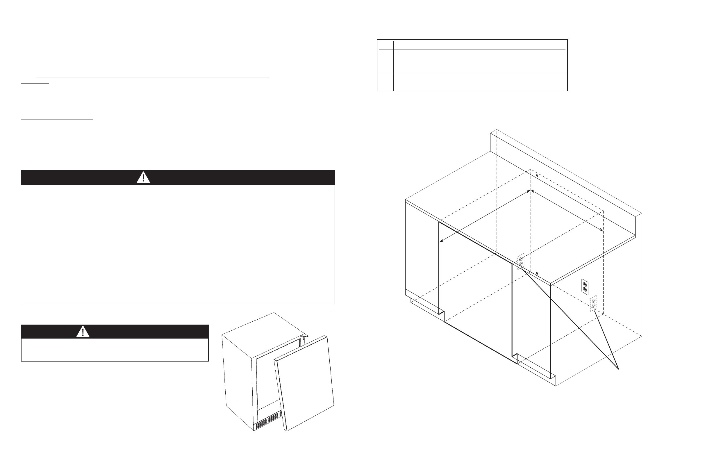
B
C
A
*
*
Cabinet Cutout
*Optional: Cutout
for electrical outlet
can be placed in
adjacent cabinetry.
IMPORTANT - PLEASE READ AND FOLLOW
••
Before beginning, please read these instructions completely and carefully.
• Do not remove permanently affixed labels, warnings, or plates from the product. This may void the warranty.
• Please observe all local and national codes and ordinances.
• Please ensure that this product is properly grounded.
• The installer should leave these instructions with the consumer who should retain for local inspector’s use and for future reference.
A GFI shall be used if required by NFPA-70 (National Electric Code), federal/state/local laws, or local
ordinances.
• The required use of a GFI is normally related to the location of a receptacle with respect to any
significant sources of water or moisture.
• Viking Range Corporation will NOT warranty any problems resulting from GFI outlets which are not
installed properly or do not meet the requirements below.
UNDERCOUNTER CABINET CUTOUT
AA
24” (61.0 cm)*
BB
Min. 34-1/4” (87.0 cm)
Max. 35” (88.9 cm)
CC
24” (61.0 cm)
If the use of a GFI is required
• Of the receptacle type (breaker type or portable type NOT recommended)
• Used with permanent wiring only (temporary or portable wiring NOT recommended)
• On a dedicated circuit (no other receptacles, switches or loads in the circuit)
• Connected to a standard breaker of appropriate size (GFI breaker of the same size NOT recommended)
• Rated for Class A (5 mA +/- 1 mA trip current) as per UL 943 standard)
• In good condition and free from any loose-fitting gaskets (if applicable in outdoor situations)
• Protected from moisture (water, steam, high humidity) as much as reasonably possible
, it should be:
WARNING
TToo rreedduuccee tthhee rriisskk ooff ffiirree,, eelleeccttrriiccaall sshhoocckk,, oorr iinnjjuurryy wwhheenn uussiinngg yyoouurr rreeffrriiggeerraatteedd ddrraawweerr,, ffoollllooww bbaassiicc pprreeccaauuttiioonnss
iinncclluuddiinngg tthhee ffoolllloowwiinngg::
•FOR YOUR SAFETY•
DO NOT STORE OR USE GASOLINE OR OTHER FLAMMABLE VAPORS AND LIQUIDS IN THE VICINITY OF THIS OR
ANY OTHER APPLIANCE. THE FUMES CAN CREATE A FIRE HAZARD OR EXPLOSION.
IItt iiss yyoouurr rreessppoonnssiibbiilliittyy ttoo bbee ssuurree yyoouurr rreeffrriiggeerraatteedd ddrraawweerr iiss::
•located so the front is not blocked to restrict incoming or discharge air flow.
•properly leveled.
•located in a well ventilated area.
•connected to the proper kind of outlet, with the correct electric supply and grounding. A 115 volt, 60 Hz, 15 amp
fused electrical supply is required.
•not used by anyone unable to operate it properly.
•used only for its intended purpose.
•properly maintained.
NNOOTTEE::
Time delay fuse or circuit breaker is recommended.
•SAVE THESE INSTRUCTIONS•
PROPER DISPOSAL OF YOUR OLD REFRIGERATION PRODUCT
DANGER
SUFFOCATION HAZARD
Remove doors from your old refrigerated drawer. Failure to do so can
result in child entrapment, which can cause death or brain damage.
IMPORTANT: Child entrapment and suffocation are not problems of the
past. Junked or abandoned refrigerated drawers are still dangerous, even if
they will sit for “just a few days.” If you are getting rid of your refrigerated
drawer, please follow the instructions below to help prevent accidents.
BEFORE YOU THROW AWAY YOUR OLD REFRIGERATION PRODUCT:
•Take off the doors.
•Leave the shelves in place so that children may not easily climb inside.
2
3
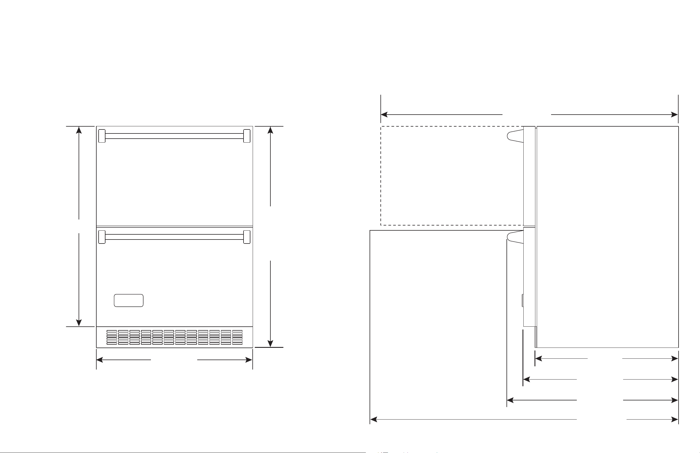
SPECIFICATIONS/DIMENSIONS PROFESSIONAL
30-3/4”
(78.1 cm)
Min. 34”
(86.4 cm)
to
Max. 34-3/4”
(88.3 cm)
with leveling
legs fully
extended.
23-7/8” (60.6 cm)
26-7/8” (68.3 cm)
24-3/8” (61.9 cm)
22” (55.9 cm)
46-7/8” (119.0 cm)
48-3/4” (123.8 cm)
BBaassiicc EElleeccttrriicc DDaattaa
•115 VAC/60 Hz
•Maximum amps - 3.3
•Approximate Shipping Weight - 180 lbs. (81.8 kg)
Front View
Side View
54
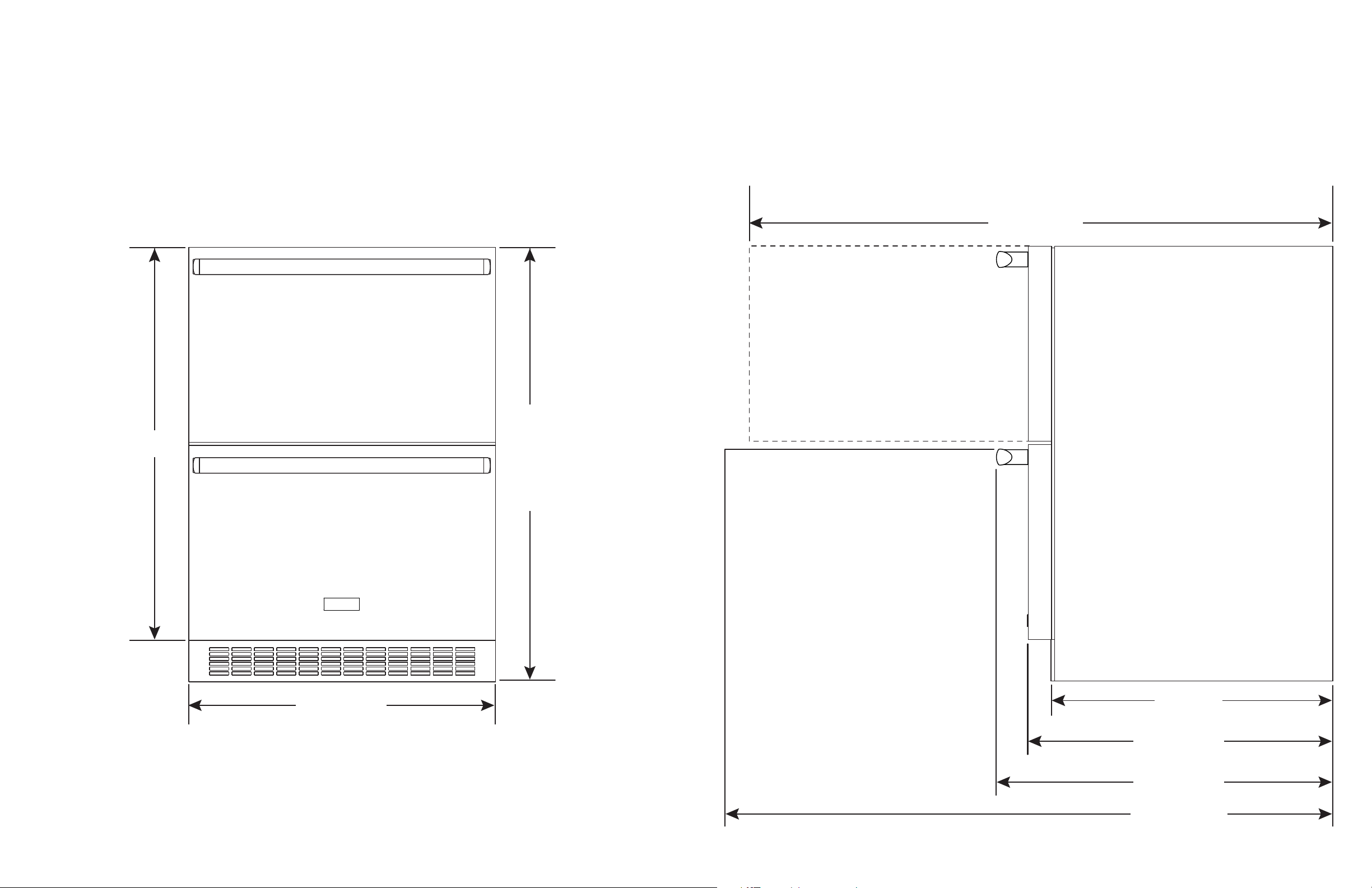
SPECIFICATIONS/DIMENSIONS DESIGNER
30-3/4”
(78.1 cm)
Min. 34”
(86.4 cm)
to
Max. 34-3/4”
(88.3 cm)
with leveling
legs fully
extended.
23-7/8” (60.6 cm)
26-7/8” (68.3 cm)
24-3/8” (61.9 cm)
22” (55.9 cm)
46-1/2” (118.1 cm)
48-3/4” (123.8 cm)
BBaassiicc EElleeccttrriicc DDaatta
•115 VAC/60 Hz
•Maximum amps - 3.3
•Approximate shipping weight - 180 lbs. (81.8 kg)
a
Front View
Side View
76
GENERAL INFORMATION
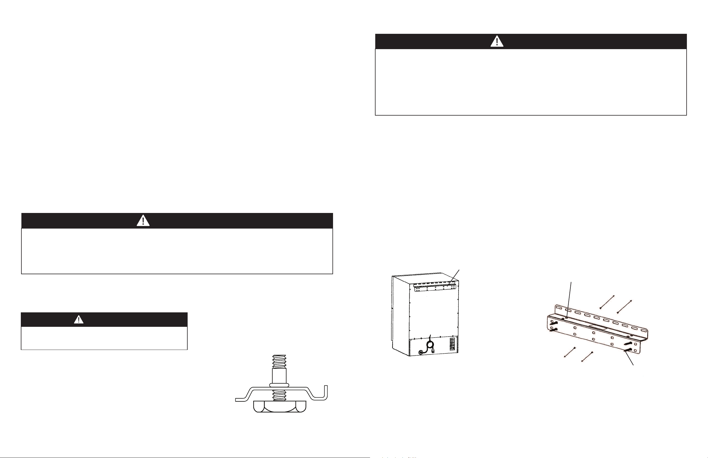
FIGURE 4
Remove these screws to seperate
upper and lower sections of anti-tip
bracket.
To Refrigerated
Drawer Cabinet
To wall
1/4” Lag screws
into wall
FIGURE 3
Anti-Tip device
UUnnppaacckk
1. Remove banding from bottom of carton. Lift carton up and off of the unit.
2. Remove all tape and packaging material from the outside and inside of the cabinet.
. Keep all carton packaging until your unit has been thoroughly inspected and found to be in good condition.
3
AREA REQUIREMENTS
Units Certified for Indoor Use - (black outer cabinet)
MUST BE INSTALLED IN AN AREA PROTECTED FROM THE ELEMENTS, SUCH AS WIND, RAIN, WATER (SPRAY OR
DRIP).
1. Place unit so the front side will be completely unobstructed to provide proper air flow. The unit may be closed in
on the top and three sides, but the front
Installation should be such that the cabinet can be moved for servicing if necessary.
2. Unit should be in a well ventilated area. Best results are obtained at temperatures between 55°F (12.8°C) and 80°F
(27°C) for built-in products and 55°F (12.8°C) and 90°F (32°C) for freestanding products.
3. Provisions for electricity and water connection should be determined before placing unit in proper place.
Units Certified for Outdoor Use - outdoor models contain a T after the base model number (ex. VURD144T) and
have a stainless steel outer cabinet.
MUST BE INSTALLED IN AN AREA PROTECTED FROM THE ELEMENTS, SUCH AS WIND, RAIN, WATER (SPRAY OR
DRIP).
1. Place unit so the front side will be completely unobstructed to provide proper air flow. The unit may be closed in
on the top and three sides, but the front
Installation should be such that the cabinet can be moved for servicing if necessary.
2. Unit should be in a well ventilated area with temperature above 40°F (4°C) and below 110°F (43°C).
3. Provisions for electricity should be determined before placing unit in proper place.
MMUUSSTT BBEE
MMUUSSTT BBEE
unobstructed for air circulation and proper operation.
unobstructed for air circulation and proper operation.
WARNING
IIMMPPOORRTTAANNTT!!
Disconnect power source before adjusting leveling legs. A cabinet “anti-tip” device is mounted to the back of your
refrigerated drawer. If installation is a built-in undercounter application, you do not need to apply this feature. If your
installation is a free-standing application with no counter top directly above the top of the refrigerated drawer, you
must apply this feature to prevent the unit from tipping forward when the drawers are pulled out. the “anti-tip” device
is attached at the back of each cabinet. Please see installation instructions supplied with the “anti-tip” device.
INSTALLING ANTI-TIP DEVICE
CAUTION
cabinet anti-tip device is mounted to the back of your refrigerated drawer unit. If your installation is a built-in
A
ndercounter application with a countertop directly above the unit, this item can be removed. It does not need to be
u
applied.
If your unit is a free-standing application with no countertop directly above the top of the unit, you must apply this
feature to prevent the unit from tipping forward when the drawers are pulled out. The anti-tip device is installed on the
back of the unit. The anti-tip device reduces the chance of personal injury as well as property damage when properly
installed between the back of the unit and the adjacent wall. Please see the following instructions for installing the antitip device.
1. Push the unit against the wall so that the anti-tip bracket is flush to the wall adjacent to the back panel. Level
the unit with the leveling legs provided in the cabinet bottom. (See Leveling Legs on previous page.)
2. Using a pencil and the bracket as a template, trace the bracket on the wall, making sure two of the screw holes are
aligned with a stud in the wall.
3. Pull the unit away from the wall.
4. Remove the screws that connect the upper and lower sections of the anti-tip bracket.
5. Place the bracket on the wall and mark and drill 3/16” diameter Pilot holes for the provided 1/4” lag screws.
Mount the lower section ot the wall with the 1/4” lag screws.
6. Move the unit into place aligning the screw holes between the upper and lower brackets and secure with the
screws removed in Step 4.
LEG LEVELER INSTALLATION
RReeaadd BBeeffoorree IInnssttaalllliinngg LLeegg LLeevveelleerrss
WARNING
Do not lay unit on top, side, back, or front. If unit is accidentally laid in
any position other than right side up, then the unit must remain in the
upright position for at least 24 hours before plugging the unit in.
1. Four leveling legs are pre-installed in the base of the unit at the factory.
2. The unit should be leveled from front to back and side to side. If floor
conditions do not allow the unit to sit level, adjust the leg levelers by turning
the required leg leveler counter-clockwise to increase the height and clockwise
to reduce the height.
8
9
 Loading...