

Viking Commercial DFUW, DFUW1541 Installation Manual
Viking Use/Installation Guide
Undercounter/Freestanding Wine Cellars
IMPORTANT - PLEASE READ AND FOLLOW
••
Before beginning, please read these instructions completely and carefully.
• Do not remove permanently affixed labels, warnings, or plates from the product. This may void the warranty.
• Please observe all local and national codes and ordinances.
• Please ensure that this product is properly grounded.
• The installer should leave these instructions with the consumer who should retain for local inspector’s use and for future reference.
A GFI shall be used if required by NFPA-70 (National Electric Code), federal/state/local laws, or local
ordinances.
• The required use of a GFI is normally related to the location of a receptacle with respect to any
significant sources of water or moisture.
• Viking Range Corporation will NOT warranty any problems resulting from GFI outlets which are not
installed properly or do not meet the requirements below.
If the use of a GFI is required
• Of the receptacle type (breaker type or portable type NOT recommended)
• Used with permanent wiring only (temporary or portable wiring NOT recommended)
• On a dedicated circuit (no other receptacles, switches or loads in the circuit)
• Connected to a standard breaker of appropriate size (GFI breaker of the same size NOT recommended)
• Rated for Class A (5 mA +/- 1 mA trip current) as per UL 943 standard)
• In good condition and free from any loose-fitting gaskets (if applicable in outdoor situations)
• Protected from moisture (water, steam, high humidity) as much as reasonably possible
, it should be:
WARNING
To reduce the risk of fire, electric shock, or injury when using your unit, follow these basic precautions:
• Read all instructions before using the unit.
• Never allow children to operate, play with, or crawl inside the unit.
• Never clean unit parts with flammable fluids. The fumes can create a fire hazard or explosion.
• Always turn the power on/off switch (located behind the air grille on top right side) to the OFF position before attempting to change
light bulbs, clean, or service the unit.
FOR YOUR SAFETY
DO NOT STORE OR USE GASOLINE OR OTHER FLAMMABLE VAPORS AND LIQUIDS IN THE VICINITY OF THIS OR ANY OTHER
APPLIANCE. THE FUMES CAN CREATE A FIRE HAZARD OR EXPLOSION.
It is your responsibility to be sure your wine cellar is:
• located so the front is not blocked to restrict incoming or discharge air flow.
• properly leveled.
• located in a well ventilated area.
• connected to the proper kind of outlet, with the correct electric supply and grounding. A 115V, 60 Hz, 15 amp fused electrical
supply is required. NOTE: Time delay fuse or circuit breaker is recommended.
• not used by anyone unable to operate it properly.
• used only for its intended purpose.
• properly maintained.
•SAVE THESE INSTRUCTIONS•
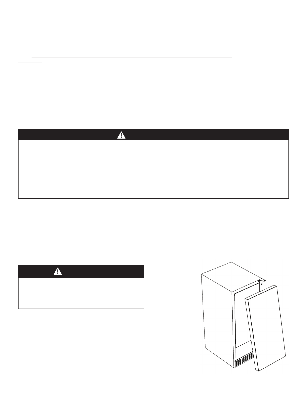
PROPER DISPOSAL (OF OLD REFRIGERATION UNIT)
DANGER
RISK OF CHILD ENTRAPMENT
Before You Throw Away Your Old Refrigeration Unit:
• Take off the doors.
• Leave the shelves in place so that children may not easily
climb inside.
IMPORTANT: Child entrapment and suffocation are not problems of the past.
Junked or abandoned refrigeration units are still dangerous... even if they will sit for
“just a few days.”
IMPORTANT:
Now that you have a new wine cellar, it is extremely important that you dispose of your
old appliance in a way that minimizes the possibility that children will find it. There
have been many cases in years past of children crawling inside junked and abandoned
refrigeration units and becoming trapped or suffocated.
Contact your municipal waste disposal authority to find out the best and safest way to
dispose of your old refrigeration unit.
2
GENERAL INFORMATION
A
B
C
Unpack
1. Remove banding from bottom of carton. Lift carton up and off of the wine cellar
2. Remove all tape and packaging material from the outside and inside of the cabinet.
3. Keep all carton packaging until your wine cellar has been thoroughly inspected and found to be in good condition.
AREA REQUIREMENTS
1. Place unit so the front side will be completely unobstructed to provide proper air flow. The unit may be closed in
on the top and three sides, but the front MUST BE unobstructed for air circulation and proper operation.
Installation should be such that the cabinet can be moved for servicing if necessary.
2. Unit should be in a well ventilated area with temperature above 55°F (13°C) and below 110°F (43°C). Best results
are obtained at temperatures between 65°F (18°C) and 80°F (27°C) for built-in models and 65°F (18°C) and 90°F
(32°C) for freestanding models.
3. Provisions for electricity should be determined before placing unit in proper place.
Units Certified for Outdoor Use - outdoor models contain a T after the base model number (ex. VUWC144T) and
have a stainless steel outer cabinet.
1. Place unit so the front side will be completely unobstructed to provide proper air flow. The unit may be closed in
on the top and three sides, but the front MUST BE unobstructed for air circulation and proper operation.
Installation should be such that the cabinet can be moved for servicing if necessary.
2. Unit should be in a well ventilated area with temperature above 40°F (4.4°C) and below 110°F (43°C). Best results
are obtained at temperatures between 60°F (16°C) and 100°F (38°C).
3. Provisions for electricity should be determined before placing unit in proper place.
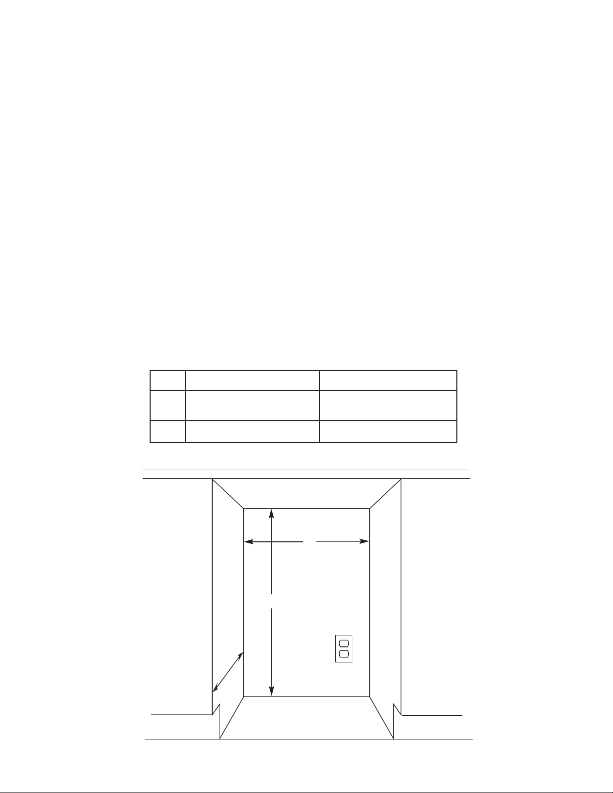
UNDERCOUNTER CABINET CUTOUT
15” W. Models
A 15” (38.1 cm)* 24” (61.0 cm)*
Min. 34-1/2” (87.6 cm)
B
Max. 35-1/8” (89.2 cm)
C 24” (61.0 cm) 24” (61.0 cm)
*Add 1/4” (.64 cm) to cutout width if door is recessed between cabinets.
24” W. Models
Min. 34-1/2” (87.6 cm)
Max. 35-1/8” (89.2 cm)
3
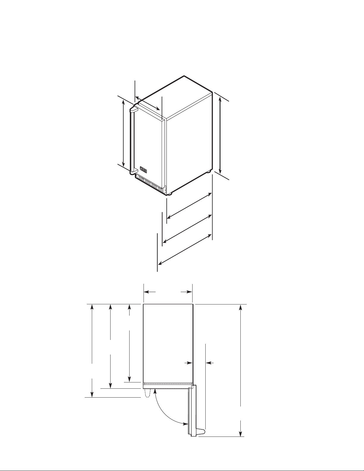
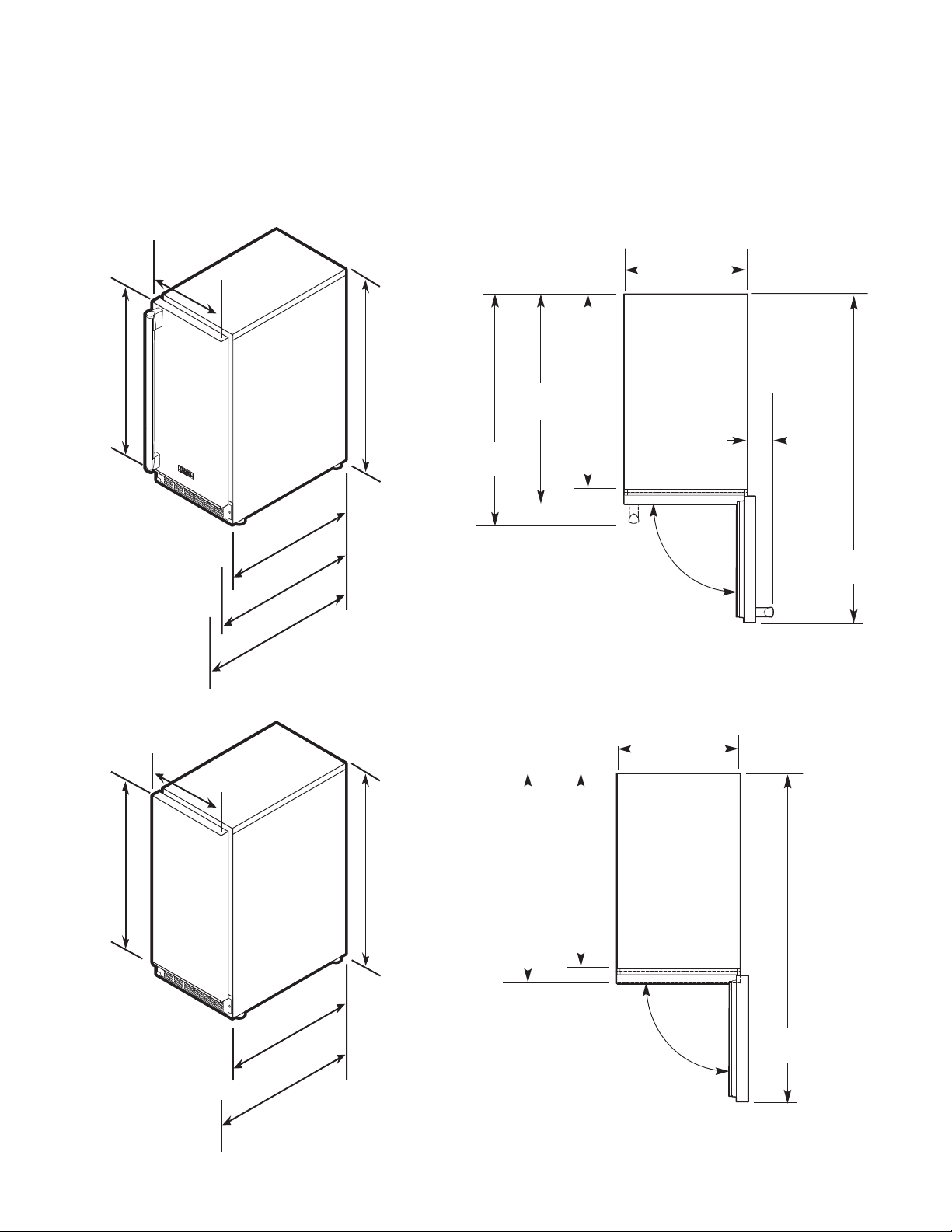
SPECIFICATIONS/DIMENSIONS
14-3/4”
(37.5 cm)
90.0°
37-3/16”
(94.5 cm)
2-1/2”
(6.4 cm)
21-3/16”
(53.8 cm)
26-1/8”
(66.4 cm)
23-5/8”
(60.0 cm)
2
1
-
3
/
1
6
”
(
5
3
.
8
c
m
)
2
3
-
5
/
8
”
(
6
0
.
0
c
m
)
2
6
-
1
/
8
”
(
6
6
.
4
c
m
)
3
4
-
1
/
4
”
(
8
7
.
0
c
m
)
m
i
n
.
t
o
3
5
”
(
8
8
.
9
c
m
)
m
ax
.
(
w
i
t
h
l
e
v
e
l
i
n
g
l
e
g
s
f
u
l
l
y
e
x
t
e
n
d
e
d
)
1
4
-
3
/
4
”
(
3
7
.
5
c
m
)
14-3/4”
(37.5 cm)
1
4
-
3
/
4
”
(
3
7
.
5
c
m
)
30-
3/
4”
(
7
8
.
1
c
m
)
PROFESSIONAL - 15”W. Models
asic Electric Data
B
•115 VAC/60 Hz
•Maximum amps - 3.0
Approximate Shipping Weight - 110 lbs. (49.5 kg)
Dimensions
VUWC 15”W.
Door Swing
VUWC 15”W.
4
SPECIFICATIONS/DIMENSIONS
2
3
-
5
/
8
”
(
6
0
.
0
c
m
)
2
1
-
3
/
1
6
”
(
5
3
.
8
c
m
)
3
0
-
3
/
4”
(
7
8
.
1
c
m
)
1
4
-
3
/
4
”
(
3
7
.
5
c
m
)
14-3/4”
(37.5 cm)
1
4
-
3
/
4
”
(
3
7
.
5
c
m
)
3
4
-
1
/
4
”
(
8
7
.
0
c
m
)
m
i
n
.
t
o
3
5
”
(
8
8
.
9
c
m
)
m
a
x
.
(
wi
t
h
l
e
v
e
l
i
n
g
l
e
g
s
f
u
l
l
y
e
x
t
e
n
d
e
d
)
2
6
-
1
/
8
”
(
6
6
.
4
c
m
)
14-3/4”
(37.5 cm)
37-3/16”
(94.5cm)
2-1/2”
(6.4 cm)
21-3/16”
(53.8 cm)
26-1/8”
(66.4 cm)
23-5/8”
(60.0 cm)
90.0°
90.0°
14-3/4”
(37.5 cm)
37-3/16”
(94.5cm)
21-3/16”
(53.8 cm)
23-7/16”
(59.5 cm)
to front of
locally supplied
custom panel
2
1
-
3
/
1
6
”
(
5
3
.
8
c
m
)
2
3
-
7
/
1
6
”
(
5
9
.
5
c
m
)
(
t
o
f
r
o
n
t
o
f
l
o
c
a
l
l
y
s
u
p
p
l
i
e
d
c
u
s
t
o
m
p
a
n
e
l
)
30
-
3
/4
”
(
7
8
.
1
c
m
)
1
4
-
3
/
4
”
(
3
7
.
5
c
m
)
14-3/4”
(37.5 cm)
1
4
-
3
/
4
”
(
3
7
.
5
c
m
)
3
4
-
1
/
4
”
(
8
7
.
0
c
m
)
m
i
n
.
t
o
3
5
”
(
8
8
.
9
c
m
)
m
a
x
.
(
w
i
t
h
l
e
v
e
l
i
n
g
l
e
g
s
f
u
l
l
y
e
x
t
e
n
d
e
d
)
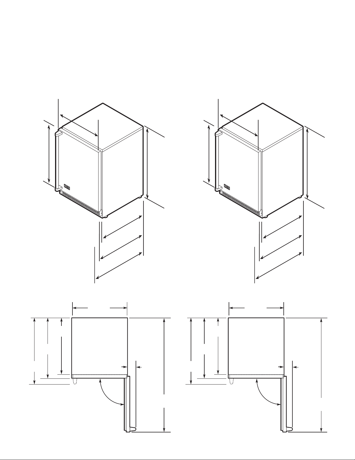
DESIGNER - 15”W. Models
asic Electric Data
B
•115 VAC/60 Hz
•Maximum amps - 3.0
Approximate Shipping Weight - 110 lbs. (49.5 kg)
Dimensions
DUWC 15”W.
Door Swing
DUWC 15”W.
Dimensions
DFUW 15”W.
Door Swing
DFUW 15”W.
5
23-7/8”
(60.6 cm)
90.0°
2-1/2”
(6.4 cm)
47-1/4”
(120.0 cm)
22”
(55.9 cm)
26-7/8”
(68.3 cm)
24-3/8”
(61.9 cm)
3
0
-
3
/
4
”
(
7
8
.
1
c
m
)
2
2
”
(
5
5
.
9
c
m
)
2
4
-
3
/
8
”
(
6
1
.
9
c
m
)
2
3
-
7
/
8
”
(
6
0
.
6
c
m
)
23-7/8”
(60.6 cm)
2
3
-
7
/
8
”
(
6
0
.
6
c
m
)
2
6
-
7
/
8
”
(
6
8
.
3
c
m
)
3
4
-
1
/4
”
(
8
7
.
0
c
m
)
m
i
n
.
t
o
3
5
”
(
8
8
.
9
c
m
)
m
a
x
.
(
w
i
t
h
l
e
v
e
l
i
n
g
l
e
g
s
f
u
l
l
y
e
x
t
e
n
d
e
d
)
SPECIFICATIONS/DIMENSIONS
23-7/8”
(60.6 cm)
90.0°
2-1/2”
(6.4 cm)
46-1/2”
(118.1 cm)
21-1/2”
(54.6 cm)
26-3/8”
(67.0 cm)
23-7/8”
(60.7 cm)
3
0
-
3
/
4
”
(
7
8
.
1
c
m
)
2
1
-
1
/
2
”
(
5
4
.
6
c
m
)
2
3
-
7
/
8
”
(
6
0
.
7
c
m
)
2
3
-
7
/
8
”
(
6
0
.
6
c
m
)
23-7/8”
(60.6 cm)
2
3
-
7
/
8
”
(
6
0
.
6
c
m
)
2
6
-
3
/
8
”
(
6
7
.
0
c
m
)
3
4
”
(
8
6
.
4
c
m
)
m
i
n
.
t
o
3
4
-
3
/
4
”
(
8
8
.
3
c
m
)
m
a
x
.
(
w
i
t
h
l
e
v
e
l
i
n
g
l
e
g
s
f
u
l
l
y
e
x
t
e
n
d
e
d
)
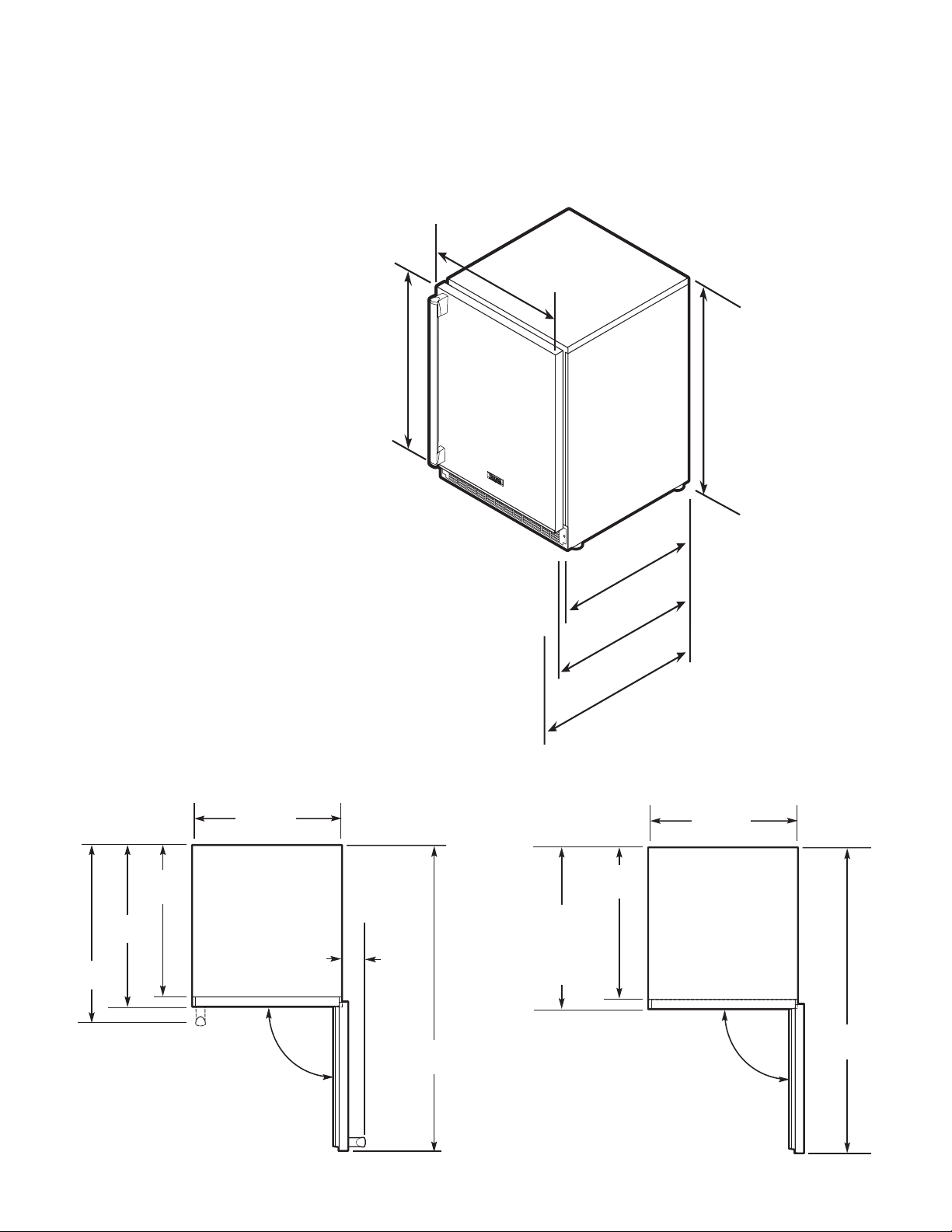
PROFESSIONAL - 24” W. Models
asic Electric Data
B
• 115 VAC/60 Hz
• Maximum amps - 3.3
• Approximate Shipping Weight
Single Zone - 140 lbs. (63.2 kg)
Dual Zone - 170 lbs. (76.5 kg)
Dimensions VUWC 24”W. - Single Zone
Dimensions VUWC 24”W. - Dual Zone
Door Swing VUWC 24”W. - Single Zone
Door Swing VUWC 24”W. - Dual Zone
6
23-7/8”
(60.6 cm)
90.0°
47-1/4”
(120.0 cm)
2-1/2”
(6.4 cm)
26-7/8”
(68.3 cm)
24-3/8”
(61.9 cm)
22”
(55.9 cm)
3
0
-
3
/
4
”
(
7
8
.
1
cm
)
2
2
”
(
5
5
.
9
c
m
)
2
4
-
3
/
8
”
(
6
1
.
9
c
m
)
2
3
-
7
/
8
”
(
6
0
.
6
cm
)
23-7/8”
(60.6 cm)
2
3
-
7
/
8
”
(
6
0
.
6
cm
)
2
6
-
7
/
8
”
(
6
8
.
3
c
m
)
3
4
-
1
/
4
”
(
8
7
.
0
c
m
)
m
i
n
.
t
o
3
5
”
(
8
8
.
9
c
m
)
m
a
x
.
(
w
i
t
h
l
e
v
e
l
i
n
g
l
e
g
s
f
u
l
l
y
e
x
t
e
n
d
e
d
)
SPECIFICATIONS/DIMENSIONS
23-7/8”
(60.6 cm)
90.0°
47-1/4”
(120.0 cm)
22”
(55.9 cm)
24-3/16”
(61.4 cm)
to front of
locally supplied
custom panel
DESIGNER - 24” W. Models
asic Electric Data
B
• 115 VAC/60 Hz
• Maximum amps - 3.3
• Approximate Shipping Weight
Single Zone - 140 lbs. (63.2 kg)
Dual Zone - 170 lbs. (76.5 kg)
Dimensions DUWC 24”W. - Single Zone
Door Swing DUWC 24”W. - Single Zone
Door Swing DFUW 24”W. - Single Zone
7
3
0
-
3
/
4
”
(
7
8
.
1
cm
)
2
1
-
1
/
2
”
(
5
4
.
6
c
m
)
2
3
-
7
/
8
”
(
6
0
.
7
c
m
)
2
3
-
7
/
8
”
(
6
0
.
6
cm
)
23-7/8”
(60.6 cm)
2
3
-
7
/
8
”
(
6
0
.
6
cm
)
3
4
”
(
8
6
.
4
c
m
)
m
i
n
.
t
o
3
4
-
3
/
4
”
(
8
8
.
3
c
m
)
m
a
x
.
(
w
i
t
h
l
e
v
e
l
i
n
g
l
e
g
s
f
u
l
l
y
e
x
t
e
n
d
e
d
)
SPECIFICATIONS/DIMENSIONS
23-7/8”
(60.6 cm)
90.0°
46-1/2”
(118.1 cm)
21-1/2”
(54.6 cm)
23-11/16”
(60.2 cm)
to front of
locally supplied
custom panel
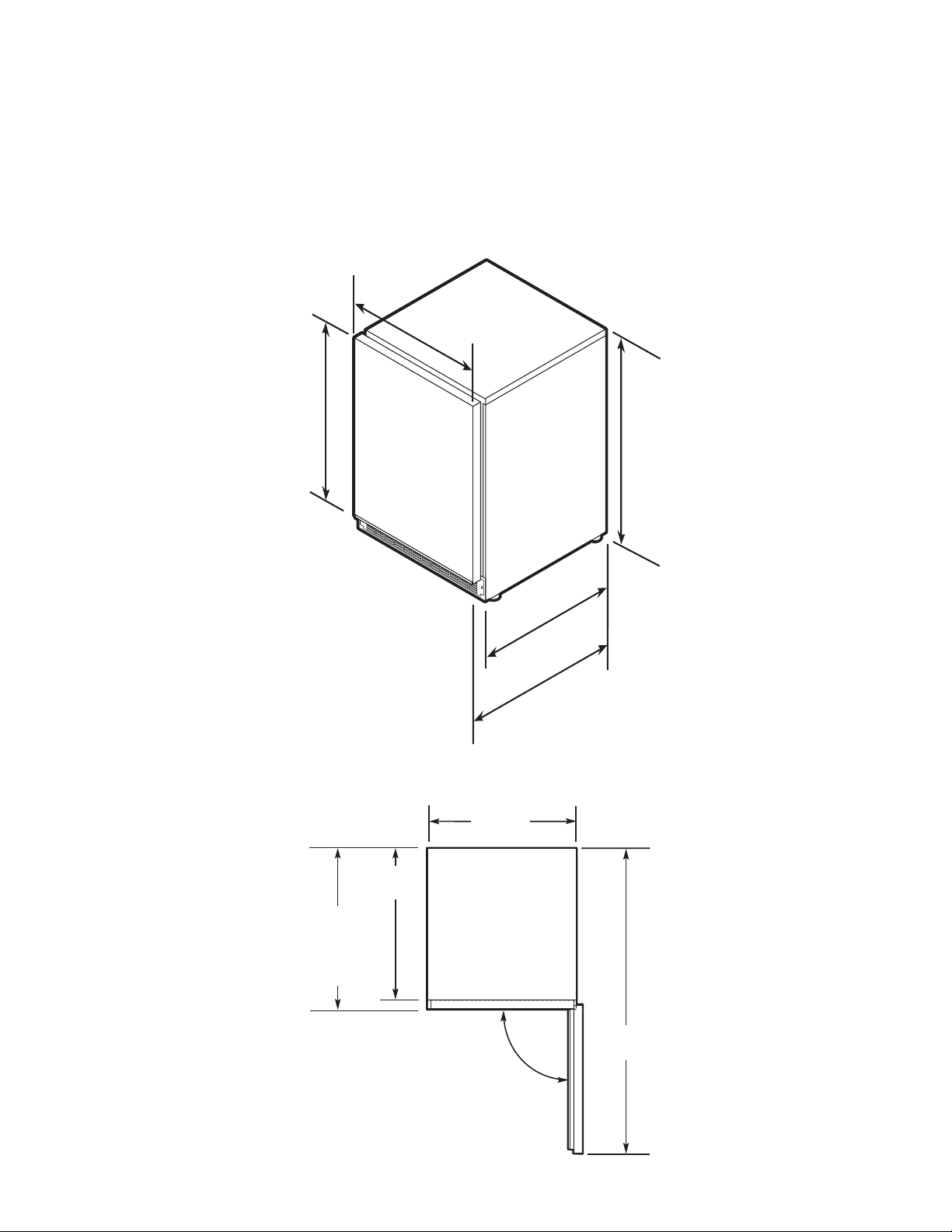
DESIGNER - 24” W. Models
Basic Electric Data
115 VAC/60 Hz
•
Maximum amps - 3.3
•
Approximate Shipping Weight
•
ingle Zone - 140 lbs. (63.2 kg)
S
Dual Zone - 170 lbs. (76.5 kg)
Dimensions DFUW 24”W. - Dual Zone
Door Swing DFUW 24”W. - Dual Zone
8
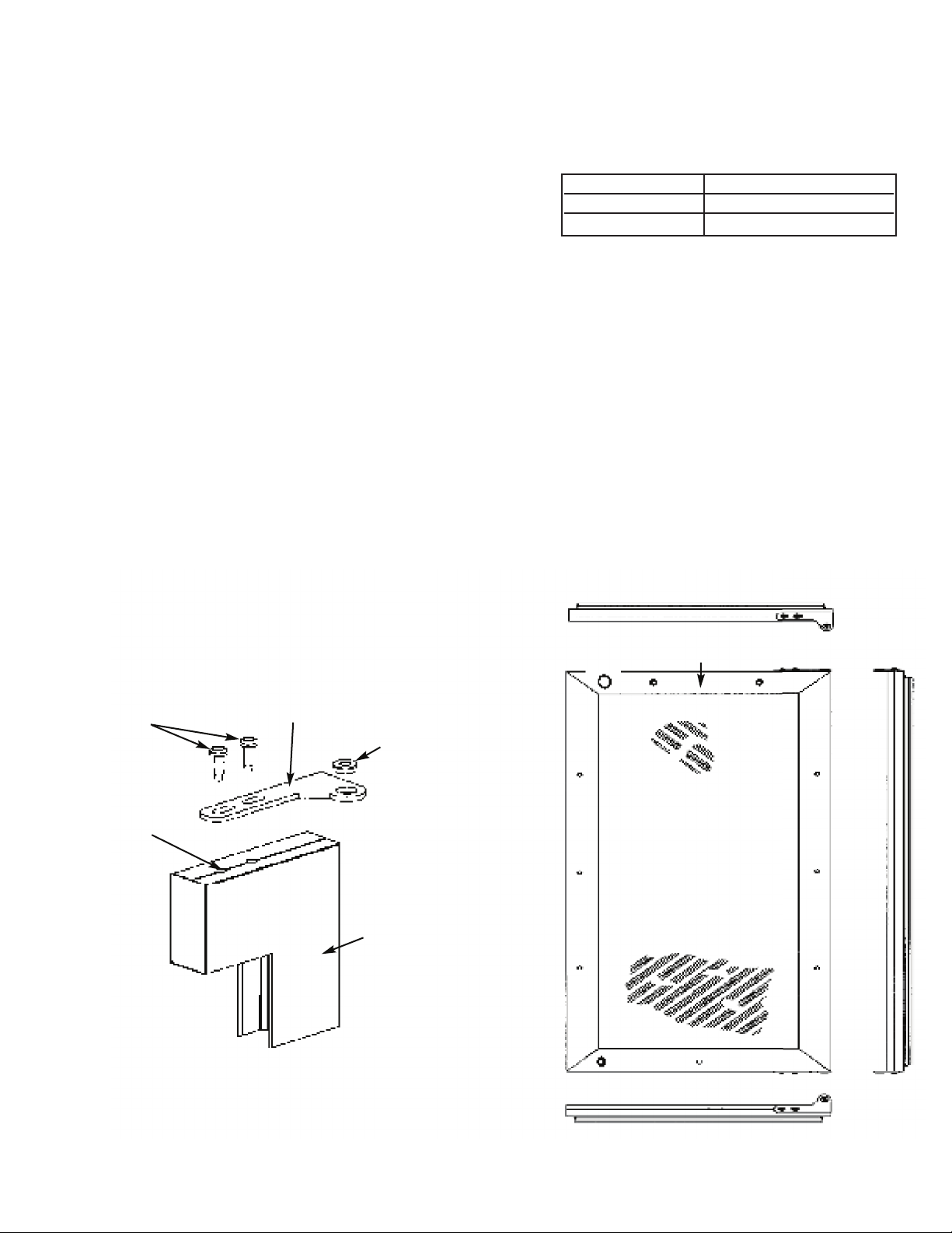
FIGURE 1 FIGURE 2
Typical Top and Bottom Door
Hinge Bracket Assembly
Door Front
Surface
Shoulder Bushing
Door
Hinge
Bracket
#10-32
Machine
Screw
Door Hinge
Screw Holes
This surface parallel to the unit.
(Right hinge door shown.)
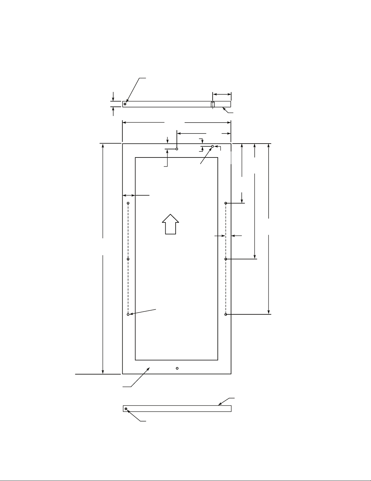
CUSTOM WOOD FRAME INSTALLATION (DFUW Model)
NOTE: Weight of wood panel must not exceed 20 lbs.
ood Screws
W
. A #10 pan head wood screw should be used to properly secure the wood panel. A total of 8 screws will be needed.
1
2. Only use pan head screws.
3. DO NOT select a screw that is longer than the wood thickness at
the screw locations.
4. Use recommended pilot holes for the frame material. (See chart)
Assembling Door Hinge Brackets
(Disregard if hinge brackets are already attached)
1. Attach the top and bottom door hinge brackets to the door with the #10-32 machine screws and a 1/8” allen head
driver as shown in Figure 1 below.
2. Press in the shoulder bushings to the top and bottom door hinge brackets. Make certain that the shoulder is to the
outside of the door as shown in Figure 1 below.
3. Test fit the door to the unit to make certain door will hang correctly. The door is hung correctly when the top of the
door is parallel to the top of the unit. Adjustments can be made by loosening the door hinge machine screws and
moving the door hinge brackets on the door.
4. Tighten all four (4) machine screws after adjustments have been made.
5. Remove the door from the unit by removing the units top hinge set screw and angling the door off of the bottom
hinge pin.
Working Material Wood Screw Size #10
Hardwood 3/32 (0.24 cm)
oftwood 5/64 (0.20 cm)
S
9
B
A
C
K
V
I
E
W
O
F
O
V
E
R
L
A
Y
P
A
N
E
L
TOP
O
F
DOOR
Pre-drilled pilot holes -
8 places
22-1/2”
(57.2 cm)
TYP
1
5-5/32”
(38.5 cm)
T
YP
7
-13/16”
(19.8 cm)
T
YP
23/32”
(1.8 cm)
TYP
1-23/32” (4.4 cm)
min. width to cover
d
oor extrusion
30-5/16”
(77.0 cm)
TYP
23/32”
(
1.8 cm)
TYP
1
5/32”
(
1.2 cm)
1
4-5/16”
(
36.4 cm)
7-5/32”
(18.2 cm)
Mounting Surface
(non-face) side
Mounting Surface
(non-face) side
M
ounting Surface
(non-face) side
1/4” x 3/8” deep hinge screw clearance hole. Locate and drill using
door hinge hole after the door has been aligned to the unit and when
the wood is positioned on door.
M
in. 5/8” (1.7 cm)
Max. 3/4” (1.9 cm)
1/4” x 3/8” deep hinge screw clearance hole. Locate and drill using
door hinge hole after the door has been aligned to the unit and when
the wood is positioned on door.
3
-7/32”
(8.1cm)
1
3/16”
(2.1 cm)
c
ounterbore 7/16”
(1.1 cm) deep
15/32”
(1.2 cm)
D
iameter
Hole
Selecting and Preparing the Wood Frame - 15”W. DFUW Model
FOR 3-1/2” TOE KICK
(COVERS THE ENTIRE DOOR EXTRUSION - LEFT HINGE)
10
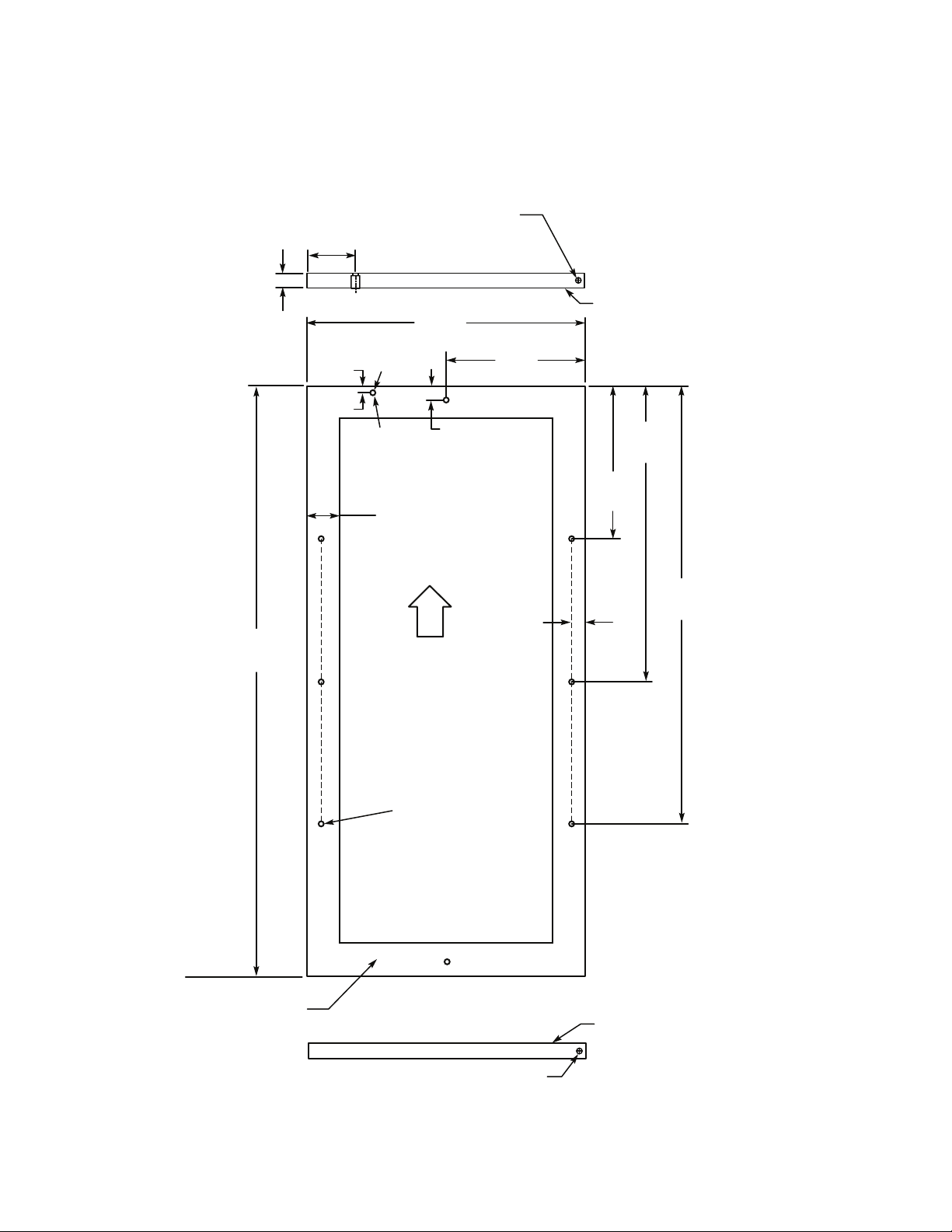
Selecting and Preparing the Wood Frame - 15”W. DFUW Model
B
A
C
K
V
I
E
W
O
F
O
V
E
R
L
A
Y
P
A
N
E
L
T
OP
OF
DOOR
Pre-drilled pilot holes -
8 places
22-1/2”
(57.2 cm)
TYP
1
5-5/32”
(
38.5 cm)
TYP
7
-13/16”
(19.8 cm)
T
YP
23/32”
(1.8 cm)
TYP
1
-23/32” (4.4 cm)
min. width to cover
door extrusion
30-5/16”
(77.0 cm)
TYP
23/32”
(
1.8 cm)
TYP
15/32”
(1.2 cm)
14-5/16”
(36.4 cm)
7-5/32”
(18.2 cm)
Mounting Surface
(non-face) side
Mounting Surface
(non-face) side
1/4” x 3/8” deep hinge screw clearance hole. Locate and
drill using door hinge hole after the door has been aligned
to the unit and when the wood is positioned on door.
1/4” x 3/8” deep hinge screw clearance hole. Locate and drill
using door hinge hole after the door has been aligned to the
unit and when the wood is positioned on door.
M
in. 5/8” (1.7 cm)
Max. 3/4” (1.9 cm)
3-7/32”
(
8.1cm)
Mounting Surface
(
non-face) side
1
5/32”
(1.2 cm)
D
iameter
Hole
13/16”
(
2.1 cm)
c
ounterbore
7/16” (1.1 cm)
deep
FOR 3-1/2” TOE KICK
COVERS THE ENTIRE DOOR EXTRUSION - RIGHT HINGE)
(
11
 Loading...