

Viking Commercial DFBB363, DFSB Installation Manual
Viking Installation Guide
U
L
C
U
L
Viking Range Corporation
111 Front Street
Greenwood, Mississippi 38930 USA
(662) 455-1200
For product information,
call 1-888-VIKING1 (845-4641)
or visit the Viking Web site at
vikingrange.com
Custom Front Models
All Refrigerator/Freezer/Side-by-Side/Bottom Mount
F20418B EN
(060508J)
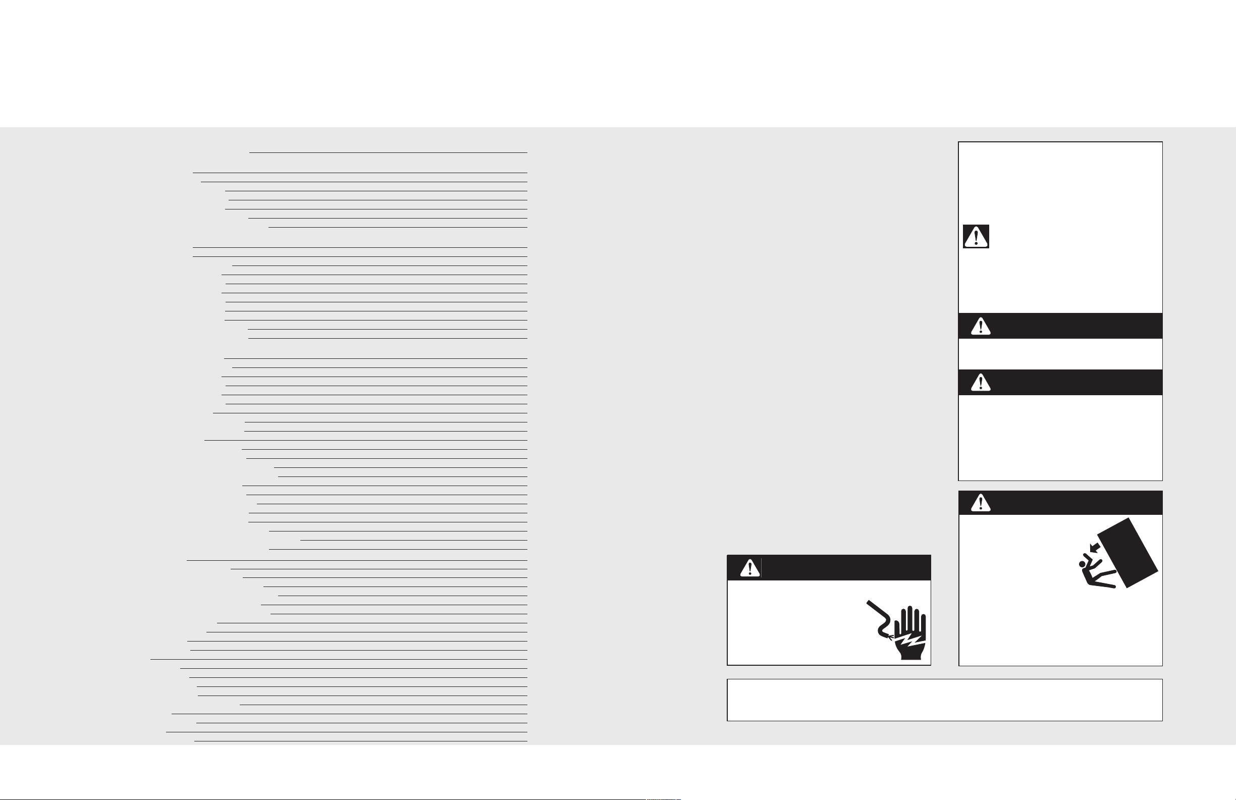
Table of Contents
Warnings and Important Information
Bottom Mount
Dimensions (36”)
Specifications (36”)
Cutout Dimensions (36”)
Anti-Tip Dimensions (36”)
Overlay Dimensions (36”)
Custom Grille Dimensions (36”)
Custom Grille Dimensions (Dual 36”)
Side-By-Side
Dimensions (42”)
Dimensions (48”)
Specifications (42”and 48”)
Cutout Dimensions (42”)
Anti-Tip Dimensions (42”)
Cutout Dimensions (48”)
Anti-Tip Dimensions (48”)
Overlay Dimensions (42”)
Overlay Dimensions (48”)
Custom Grille Dimensions (42”)
Custom Grille Dimensions (48”)
All Refrigerator/Freezer
Dimensions (30”and 36”)
Specifications (30”and 36”)
Cutout Dimensions (30”)
Anti-Tip Dimensions (30”)
Cutout Dimensions (36”)
Anti-Tip Dimensions (36”)
Dimensions (Dual 30”)
Dimensions (Dual 30”and 36”)
Dimensions (Dual 36”and 36”)
Specifications (Dual)
Cutout Dimensions (Dual 30”)
Anti-Tip Dimensions (Dual 30”)
Cutout Dimensions (Dual 30”and 36”)
Anti-Tip Dimensions (Dual 30”and 36”)
Cutout Dimensions (Dual 36”)
Anti-Tip Dimensions (Dual 36”)
Overlay Dimensions (30”and 36”)
Custom Grille Dimensions (30”)
Custom Grille Dimensions (36”)
Custom Grille Dimensions (Dual 30”)
Custom Grille Dimensions (Dual 30” and 36”)
Custom Grille Dimensions (Dual 36”)
Cabinet Information
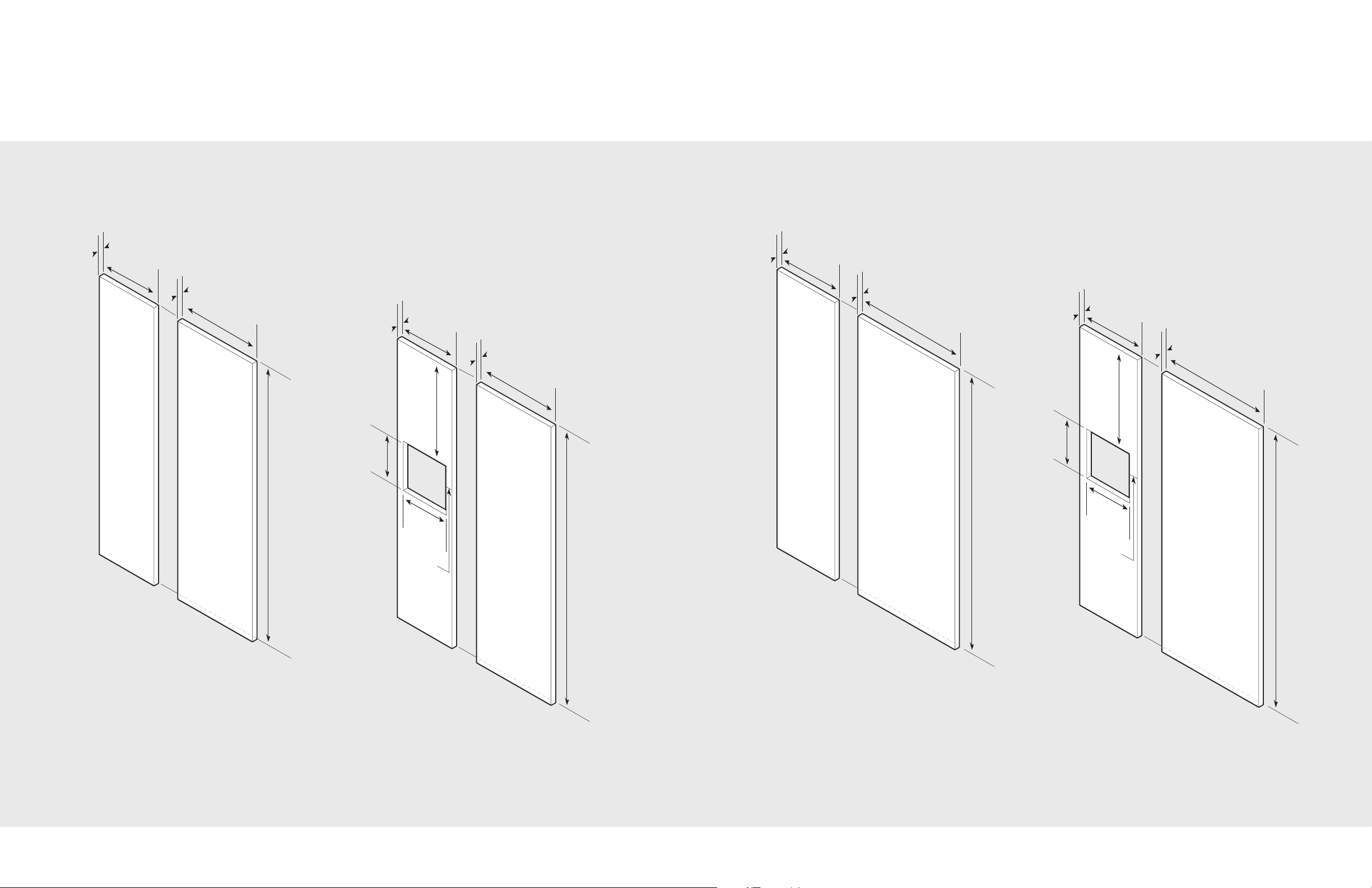
Custom Side Panel Dimensions
Custom Panel General Information
Ice and Water Dispenser Bezel Removal
Custom Door Panel Installation–Refrigerator
Custom Door Panel Installation–Freezer
Ice and Water Dispenser Bezel Installation
Custom Panel Hinge Cutout
Custom Grille Installation
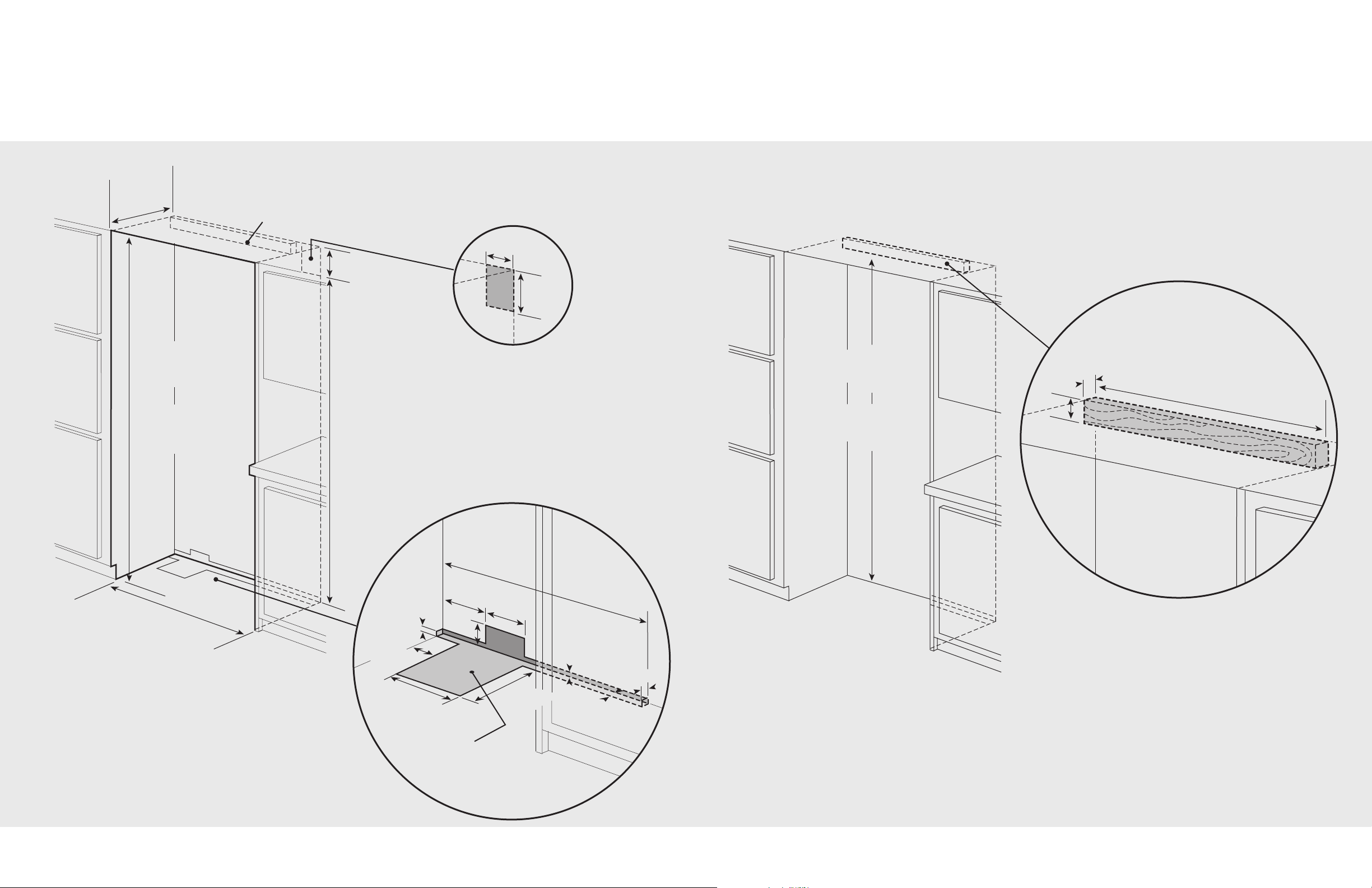
General Information
Unpacking & Moving
Installation
Hinge Adjustment
Kickplate Installation
Door Stop Adjustment
Water Filter Installation
Water Filter System Specifications
Final Installation
Performance Checklist
Control Panels
Service & Registration
2
3
4
5
6
7
8
9
10
11
12
13
14
15
16
17
18
19
20
21
22
23
24
25
26
27
28
29
30
31
32
33
34
35
36
37
38
39
40
41
42
43
45
46
46
48
49
50
52
53
55
57
58
59
61
62
63
64
65
66
67
69
IMPORTANT–Please Read and Follow
Make sure that incoming voltage is the same
•
as unit rating. An electric rating plate
specifying voltage, frequency, wattage,
amperage, and phase is attached to the
product.
• To reduce the risk of fire, electrical shock, or
injury to persons, installation work and
electrical wiring must be done by qualified
people in accordance with all applicable
codes and standards, including fire-rated
construction.
• The installer should leave these instructions
with the consumer who should retain them for
local inspector’s use and for future reference.
It is your responsibility to:
• Comply with installation specifications and
dimensions.
• Properly install unit.
• Remove any moldings or decorative panels
that prevent the unit from being serviced.
• Make sure that you have these materials (not
provided with your unit), which are necessary
for proper installation:
•1/4” (6 mm) copper tubing with shutoff
valve
•6– #8 x 3” (7.6 cm) wood screws (longer
screws may be required)
•1– Saddle valve (do not use self-piercing
feature of the valve)
• Assure that floor will support unit, door
panels and contents (approximately 1200
pounds [540 kg]).
• Provide a properly grounded electrical outlet.
• Assure that location will permit appliance
doors to open a minimum of 90˚.
W A R N I N G
ELECTRICAL SHOCK HAZARD
Disconnect power or turn
power disconnect switch to
OFF position before removing
top grille. Failure to do so can
result in death or electric shock.
Most of the unit’s weight is at the top. Extra care is needed when moving the unit to prevent tipping.
Use cardboard shipping material or plywood under unit until it is installed in the operating position
to protect floor surface.
Your safety and the safety of others is
very important.
We have provided many important safety
messages in this manual and on your
appliance. Always read and obey all
safety messages.
This is the safety alert symbol. This
symbol alerts to hazards that can
result in injury or death to you and
others.
All safety messages will be preceded by the
safety alert symbol and the word“DANGER”
or “WARNING.” These words mean:
D A N G E R
Failure to follow these instructions will
result in serious injury or death.
W A R N I N G
Failure to follow these instructions can
result in serious injury or death.
All safety messages will identify the
hazard, tell you how to reduce the chance
of injury, and tell you what can happen if
the instructions are not followed.
W A R N I N G
TIP OVER HAZARD
Appliance is top heavy
and tips easily when not
completely installed.
Keep doors closed until
appliance is completely installed and
secured per installation instructions.
Use two or more people to move and install
appliance. Failure to do so can result in death
or serious injury.
2
5
1
-7
/8
”
(13
1.8
c
m
)
2
3
-1
/1
6
”
(5
8
.6
c
m
)
3
-1/2
”
(8
.9
c
m
)
8
2
-7
/8
”
(2
1
0.5
c
m
)
m
in
.
t
o
8
4
-1
/1
6
”
(2
1
3.5
c
m
)
ma
x
.
Mea
s
u
r
e
me
n
t va
r
ie
s
(
lo
ca
ll
y s
upp
lie
d
ha
rdw
ar
e
)
2
3
1
3
/
1
6
”
(
6
0
.
5
cm)
2
4
3
/4
”
(
6
2
.
9
cm)
3
5
”
(
9
8
.
9
c
m)
36”
(9
1
.
4
c
m)
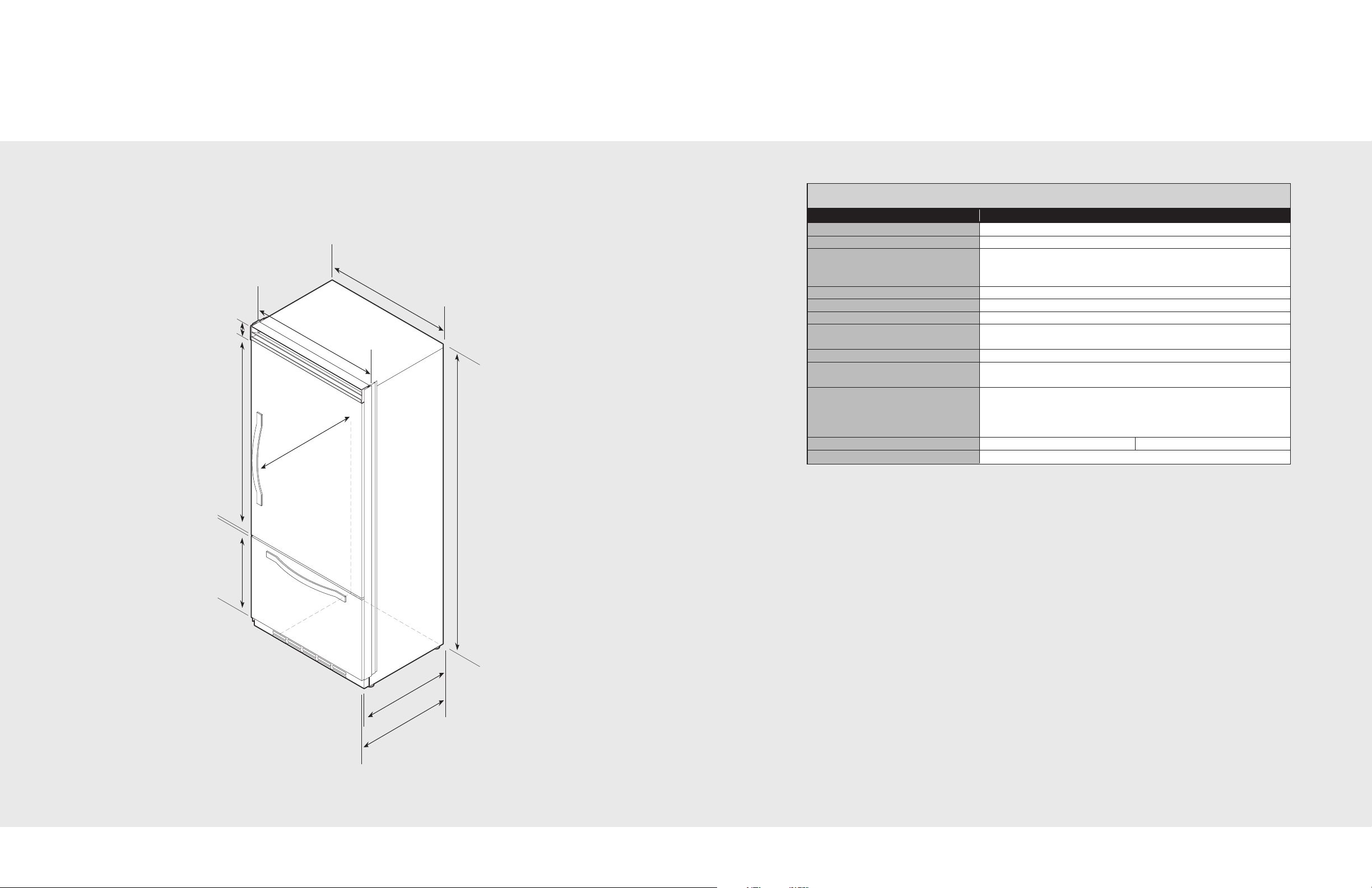
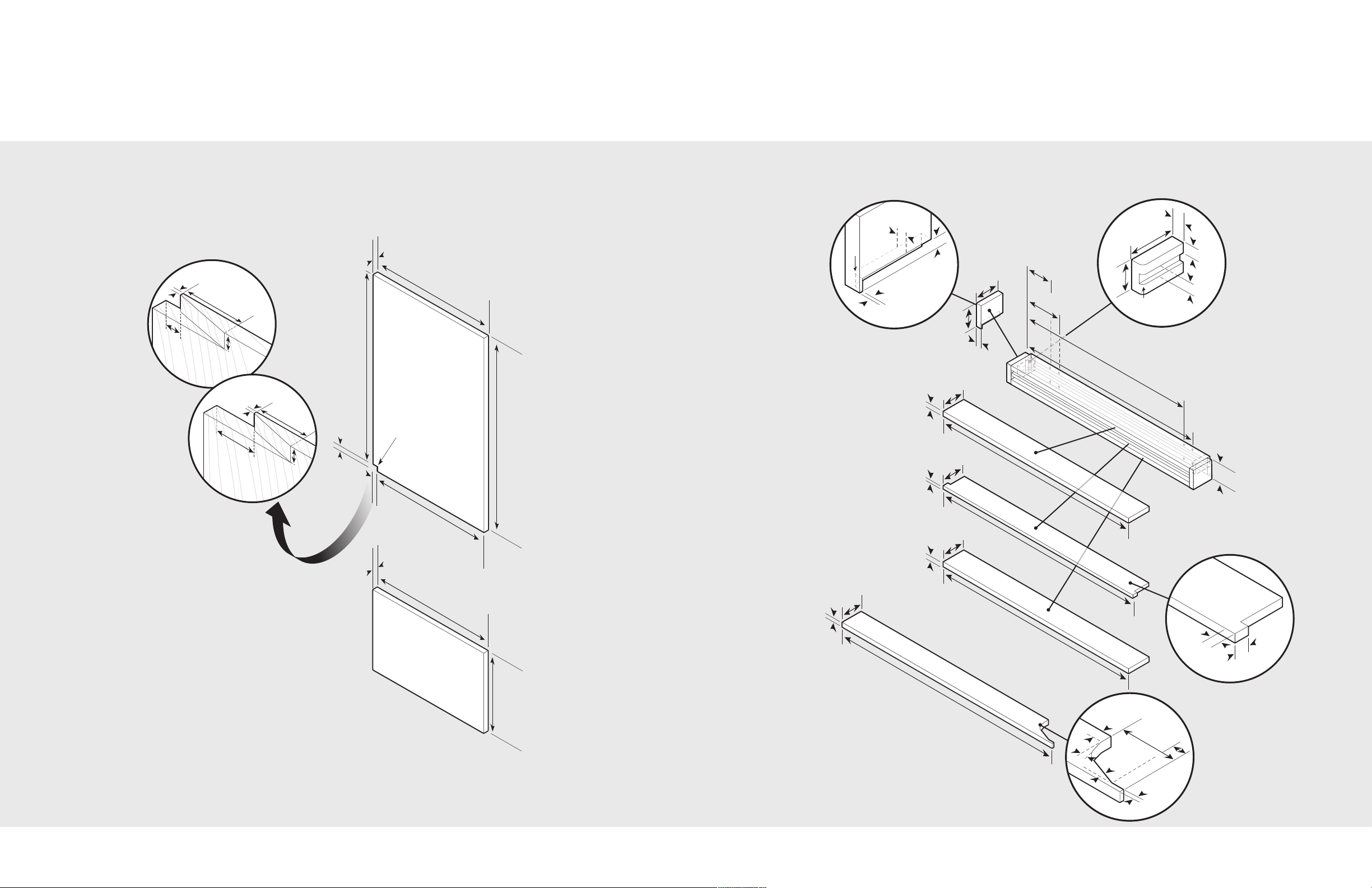
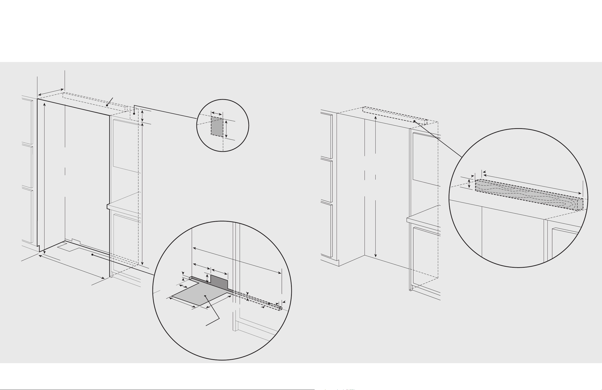
Dimensions (Bottom Mount)
Specifications (Bottom Mount)
36” Bottom Mount
36” Bottom Mount
Description DFBB363
verall width 36” (91.5 cm)
O
Overall height (from bottom) 82-3/4” (210.2 cm) min. to 84-1/16” (213.5 cm) max.
Overall depth (from rear) To front edge of side trim: 23-13/16” (60.5 cm)
To front of top grille: 24-3/4” (62.9 cm)
To front edge of door trim: 24” (61.0 cm)
Cutout width 36” (91.5 cm)
Cutout height 82-7/8” (210.5 cm) min. to 84-1/16” (213.5 cm) max.
Cutout depth 24” (61.0 cm) min.*
Electrical requirements 115 volt, 60 Hz, 15 amp dedicated circuit; 3-wire cord with
grounded 3-prong plug attached to product
Maximum amp usage 9.9 amps
Inlet water 1/4” copper tubing inlet waterline; minimum 20 psi;
requirements maximum 120 psi
Overall interior dimensions
Refrigerator 15.2 cu. ft. (431 liters)
Freezer 5.1 cu. ft. (145 liters)
Total capacity 20.3 cu. ft. (576 liters)
Maximum panel weight Fresh food 45 lbs. (20.4 kg) Freezer 20 lbs. (9.0 kg)
Approximate shipping weight 500 lbs. (227.3 kg)
*Full overlay models fit flush in 25” (63.5 cm) deep cabinet openings. They can be installed in standard 24” (61.0 cm)
deep openings. The door faces and top grille will protrude 3/4” (1.9 cm) into the room.
3
4
9”
(
22
.
9
c
m
)
73-
3/
8”
(18
6.4
c
m
)
82-
7/8”
(2
1
0
.5
c
m)
mi
n
.
a
n
t
i
-
t
ip
b
o
ar
d
&
o
p
en
ing
he
igh
t
8
4
-1
/1
6
”
(21
3
.
5
c
m)
ma
x.
an
t
i-t
ip
boa
r
d
&
ope
n
in
g h
e
ig
h
t
36”
(9
1.5 c
m
)
2
4”
(61
.
0 c
m
)
Electric outlet location
Water line entry area
36”
(
9
1
.5
c
m)
6-
3
/
4”
(
17
.1
cm)
7-
5
/8”
(
1
9
.4
c
m
)
3”
(7.6
cm
)
5/8
”
(1.
5 c
m)
5/8
”
(1.
5 c
m)
10-
1/2”
(26
.7
cm)
5
/8
”
(1.5
cm
)
10-
3/4
”
(27
.3
cm)
1”
(
2.
5
cm
)
3-5
/8
”
(9.
2 c
m)
Op
t
ion
al f
loo
r
wat
er
lin
e e
ntr
y
See
a
n
t
i
-
t
i
p
b
o
a
rd
in
s
t
a
l
la
t
io
n
6
”
(1
5
.
2
c
m)
9
”
(2
2
.
9
c
m)
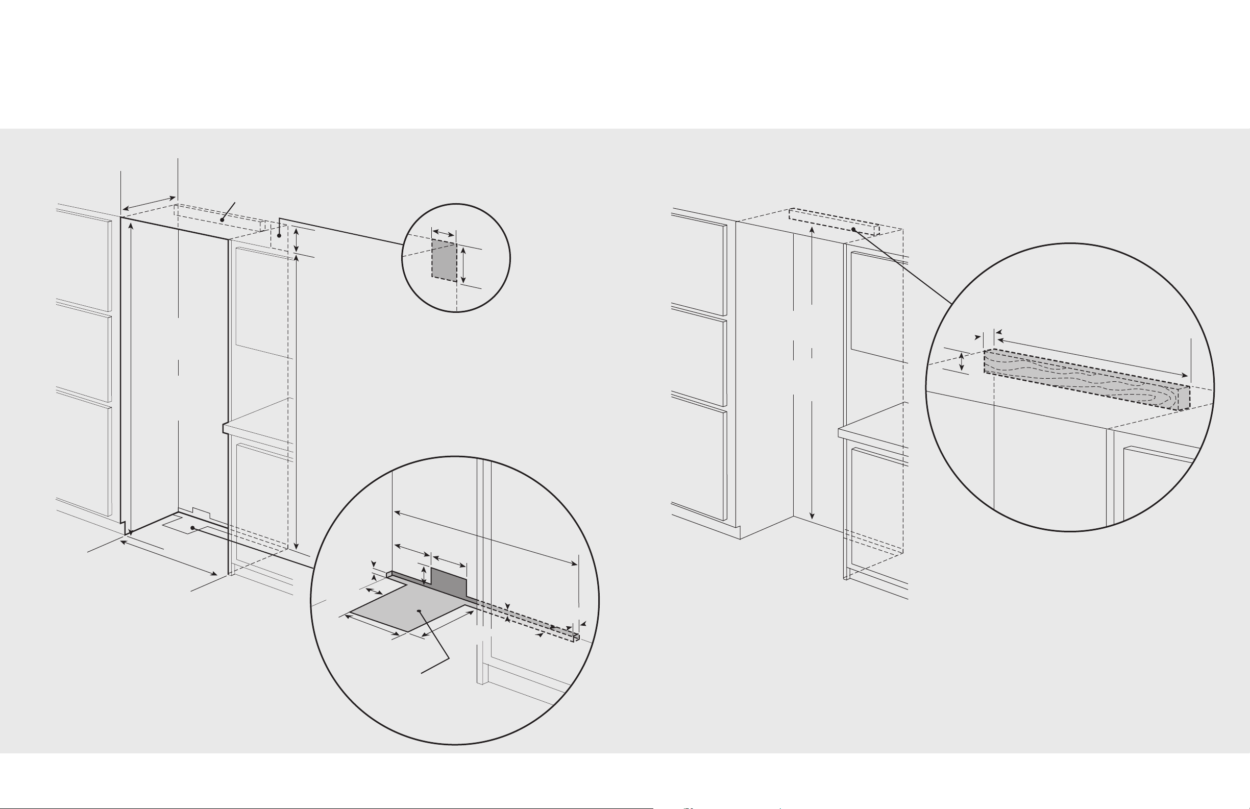
Cutout Dimensions (Bottom Mount)
One 2”x 4” mounting board
1-1/2” (3.8 cm) x 3-1/2” (8.9 cm)
Note: If unit is installed deeper than 24” (61.0 cm), then shim
behind the mounting board by the difference.
Bottom of anti-tip board is 3-7/8” (9.8 cm) below opening height.
Note: Top of unit must be placed firmly under anti-tip board.
Anti-tip location
79
-
3/8”
(2
01
.6
cm)
mi
n
.
t
o b
ot
t
o
m
of
a
n
t
i
-
t
i
p
bo
a
r
d
80
-
1/2”
(20
4.6
cm
) m
a
x
.
t
o b
ot
t
o
m
of
a
n
t
i
-
t
i
p
bo
a
r
d
29”
(
7
3
.7 cm
)
3
-1
/2”
(8.
9 c
m
)
1-1
/
2”
(3.
8 c
m)
Anti-Tip Dimensions
(Bottom Mount)
36” Bottom Mount
36” Bottom Mount
65
Reverse dimensions
for other end.
1
/
2
”
(
1.
2
7
c
m
)
1-
1/
2”
(3.
8
1
c
m
)
1/4”
R
a
d
i
u
s
(
.
6
4
c
m
)
2-
3
/4
”
(
6.
98
c
m
)
1
/
2
”
(
1
.
2
7
c
m)
3
/
4
”
(
1.
9
0
c
m)
1/
2”
(1
.
2
7 c
m
)
1
/
8
”
(
.
31 c
m
)
1
/2”
(1
.2
7
c
m)
1/4”
Ra
d
i
u
s
1/4” Radius
(
1
.
2
c
m
)
(1.2 cm)
1/4”
Ra
d
i
u
s
(
.
6
4
c
m
)
7
/8”
(
2
.
2
2
cm
)
1
/
2
”
(
1.
2
7
c
m
)
34”
(
8
6
.
3
6
c
m
)
34”
(
8
6
.
3
6
cm
)
3/4
”
(
1
.
9
0
c
m)
1/2
”
(
1
.
2
7
c
m)
3/4
”
(
1
.
9
0
c
m)
3-
3/
4
”
(9
.
5
2 c
m)
3-
3/
4
”
(9
.
5
2
c
m)
3-
5/
8”
(9
.2
0
c
m)
33-
15
/
16”
(
8
6
.
2
0
cm
)
3”
(
7
.
6
2
c
m
)
3”
(7
.6
2 c
m)
3/
4”
(1
.
9
0 c
m)
35-
1/
2”
(
9
0
.
1
7
c
m
)
1/2”
(
1
.
2
7 c
m)
3-
1/
8”
(
7
.
9
3
cm)
Op
ti
ona
l h
ing
e
c
ov
e
r
3
2
-
3
/1
6
”
(
81
.
75
c
m
)
5
-
1
7
/3
2
”
(
1
4
.
10
c
m
)
4
-
1
1
/6
4
”
(
10
.
59
c
m
)
3
0
-
2
7
/
3
2
”
(
78
.
34
c
m
)
3
2
5
/
3
2
”
(
9
.6
0
c
m
)
2
7
/
3
2
”
(
.
84
c
m
)
9/16
”
(
1
.
4
2 c
m)
1
/4
”
(
.
6
3
5
c
m
)
1
6
.
5
˚
20
.
0
˚
2
-1
/
8
”
(
5
.
4
cm
)
35
-
1/4”
(89.5
cm
)
2
3
-1
/
1
6
”
(58
.6 c
m)
3
/4
”
(1
.
9
c
m)
35
-
1/
4”
(8
9
.5
cm
)
34-
3
/8
”
t
o
not
c
h
(
86.6
c
m)
7/8”
(
2.
2
c
m)
5/8”
(
1.
6
c
m
)
51-7/
8”
(
1
3
1.8
c
m
)
51-1/4”
(
1
3
0.2
c
m)
3
/4
”
(
1
.
9
c
m
)
No
te
: Co
r
ne
r
n
otch
i
s
f
o
r
l
eft
h
in
g
e
d
oor.
(R
e
v
e
r
s
e
for
ri
g
h
t
hi
n
ge
)
S
ee
pa
g
e
5
0 f
or
cu
t
ou
t
i
n
st
r
u
ct
i
on
s
7
/8
”
(
2.
2c
m)
5
/8
”
(
1.
6
c
m
)
1
/
8
”
(
0
.
3
c
m
)
2
”
(
5
.
1
c
m
)
For Models made
before 9/22/06
Note: Inset shown upside down.
1
-1
3/
16”
(
4.
60
cm)
5/
8
”
5/8”
(
1.
6
c
m)
(1.6 cm)
3
”
(
7.
62
c
m
)
3/32
”
(
.2
4 c
m
)
5/8”
5/
8
”
(
1.
6
c
m)
For Models made
after 9/22/06
Note: Inset shown upside down
Overlay Dimensions (Bottom Mount)
Custom Grille Dimensions (Bottom Mount)
36” Custom Panels
Note: Panel overlays must be dry, solid, straight one
piece panels. The use of multiple panel pieces to
achieve the dimensions is not recommended.
Important: A 1/4” back panel is required. Make it 1/4”
smaller in width and 7/8” shorter in height than the
dimensions shown. Locate it to achieve a 1/8” inset on
the top and both sides and a 3/4” inset on the bottom.
36” Custom Grille
8
7
75-
15/16”
(
1
9
2
.9
c
m)
3
-1
/2
”
(
8
.
9 c
m)
8
2
-
7
/
8
”
(
2
1
0
.5
c
m
)
m
i
n
.
t
o
8
4
-
1
/
1
6
”
(
2
1
3
.5
c
m
)
m
a
x
.
Measu
r
em
en
t va
r
ies
(l
o
c
a
l
l
y
s
u
p
pli
e
d
h
a
r
d
w
a
r
e
)
23-
13/
16”
(6
0
.5
cm
)
24
-
3/
4
”
(6
2
.9
cm
)
4
1
”
(
1
0
4
.
1
c
m
)
4
2
”
(
1
0
6
.
7
c
m
)
3
2
5/
3
2”
(9
.
6
0 c
m)
2
7/3
2”
(
.8
4
c
m)
9/
1
6”
(1
.
4
2
c
m)
1/
4
”
(.6
3
5
c
m)
16.
5˚
20.
0˚
Note: This part should be
located at the center of the
grille. If desired, two per grille
can be used by dividing the
length of the grille into thirds.
1/
2
”
(
1
.
2
7
c
m
)
1-
1/
2
”
(
3
.
8
1
c
m
)
1/
4”
R
a
d
i
u
s
(
.
6
4 c
m
)
2-
3
/
4
”
(
6
.
98
c
m
)
1/
2”
(
1
.
2
7
c
m
)
3/
4”
(
1
.
9
0
c
m)
3/8”
(0.38 cm)
1/2”
(1.27 cm)
R
3/32”
(0.09 cm)
3/4”
(1.90 cm)
3/4”
(1.90 cm)
3/4”
(1.90 cm)
13/32”
(
1.03 cm)
9/16”
(
1.43 cm)
1/8”
(.32 cm)
Grille support
2
-
7
/
8”
(7.
30
c
m)
1
”
(2.
54
c
m
)
1/2
”
(1
.2
7
c
m
)
1
/
8
”
(
.
3
1
c
m
)
1
/
2
”
(
1.
2
7
c
m
)
1/
4
”
R
a
d
iu
s
1/4” Radius
(
1
.
2
c
m)
(1.2 cm)
1/
4
”
R
a
d
iu
s
(
.
6
4
c
m)
Reverse dimensions
for other end.
7/
8”
(2.
22
cm
)
1/2
”
(1
.
27
c
m)
1/2
”
(
1.
2
7
c
m
)
3-
1/
8
”
(
7.
9
3 c
m
)
Opt
i
on
al
hing
e
c
over
1/2”
(
1.
2
7
c
m
)
3-
5/
8”
(
9.
2
0
cm
)
3/4”
(
1.
9
0
c
m
)
3/4
”
(
1.
9
0
c
m
)
3-
3/
4”
(
9.
5
2
cm
)
3-
3/
4”
(
9.
5
2
c
m
)
3
”
(
7.
6
2
cm
)
3
”
(7.
6
2
c
m
)
3/4
”
(1
.9
0
c
m)
7
1-1
/2”
(18
1.61
cm)
70”
(
17
7.
80
cm
69-
15/
16”
(1
7
7
.6
4
cm
)
70”
(1
7
7
.8
0
c
m
)
68
-
3
/6
4
”
(
1
7
2
.
8
3
cm
)
6
6
-27
/
32
”
(
1
6
9
.
7
8
cm
)
4-
1
1/
64
”
(1
1
.
2
7
cm)
5-
1
7
/
3
2
”
(1
4
.
0
4
cm
)
3
0
-
2
7
/
3
2
”
(7
8
.
3
4
cm
)
32
-
3
/
1
6
”
(
8
1
.
7
5 cm
)
4
0-
11
/
64
”
(
1
0
2
.
0
3
cm
)
4
1-
25/
64”
(
1
0
5
.
1
3
c
m
)
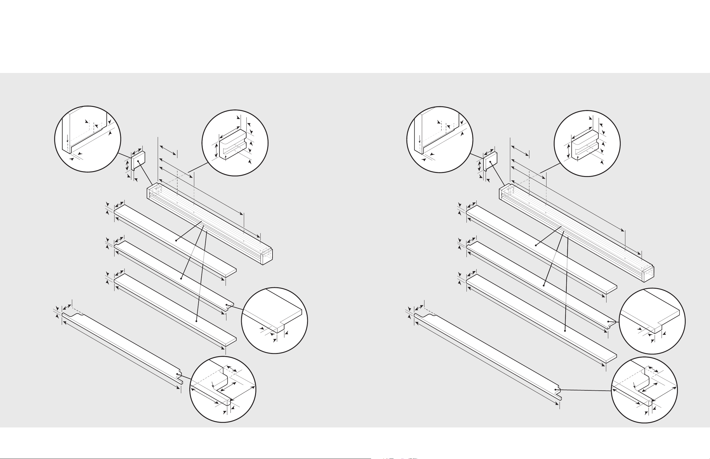
Custom Grille Dimensions (Bottom Mount)
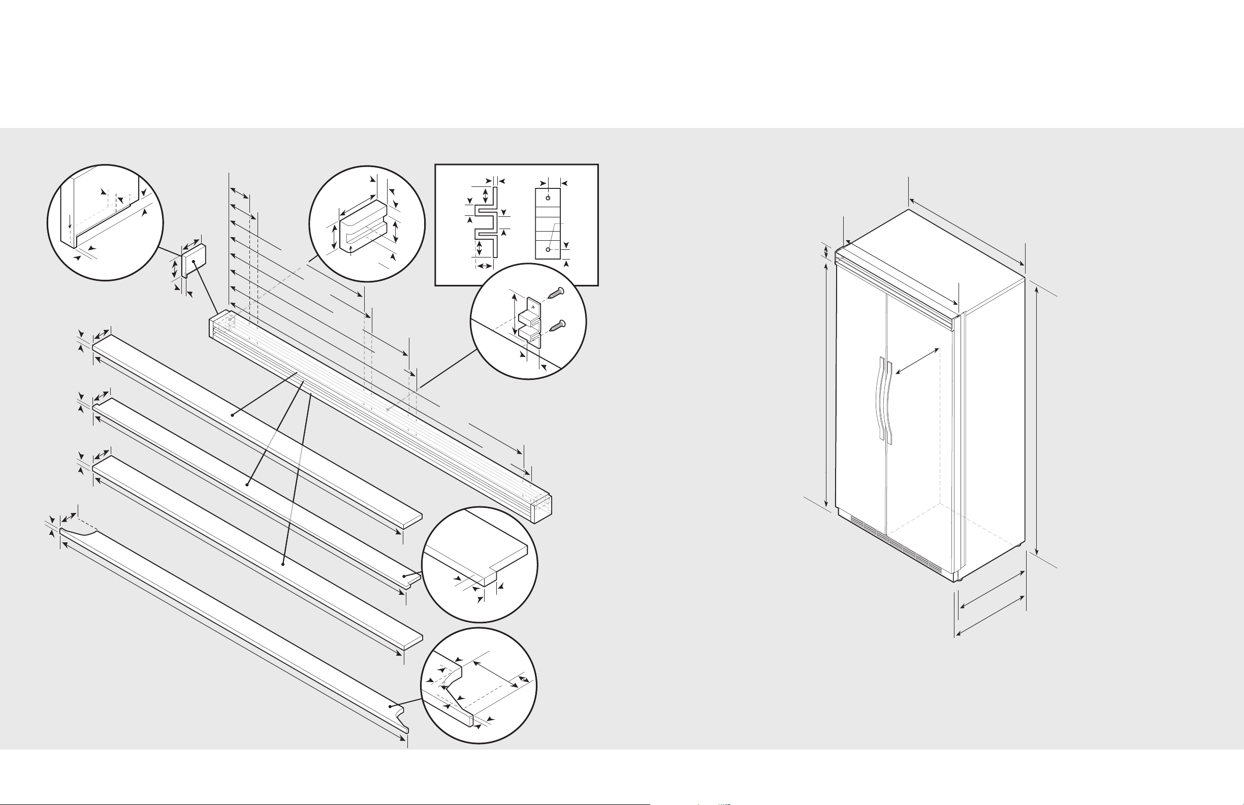
Dimensions (Side-By-Side)
Dual 36” Custom Grille
42” Side-By-Side
10
9
75-
15/
16”
(
1
9
2
.9
cm)
3
-
1
/
2”
(
8
.
9 c
m)
82-7/
8”
(
21
0
.
5
c
m
)
mi
n
.
to
84-1/
16”
(
21
3
.
5
c
m
)
m
ax
.
2
3
-
1
3
/
1
6
”
(60
.5
cm
)
2
4-
3
/4
”
(62
.9
cm
)
4
7
”
(
1
1
9
.
4
c
m
)
4
8
”
(
1
2
1
.
9
cm
)
M
easu
rem
en
t v
a
r
i
es
(l
o
c
a
l
l
y
su
p
p
li
e
d
h
ard
w
a
r
e
)
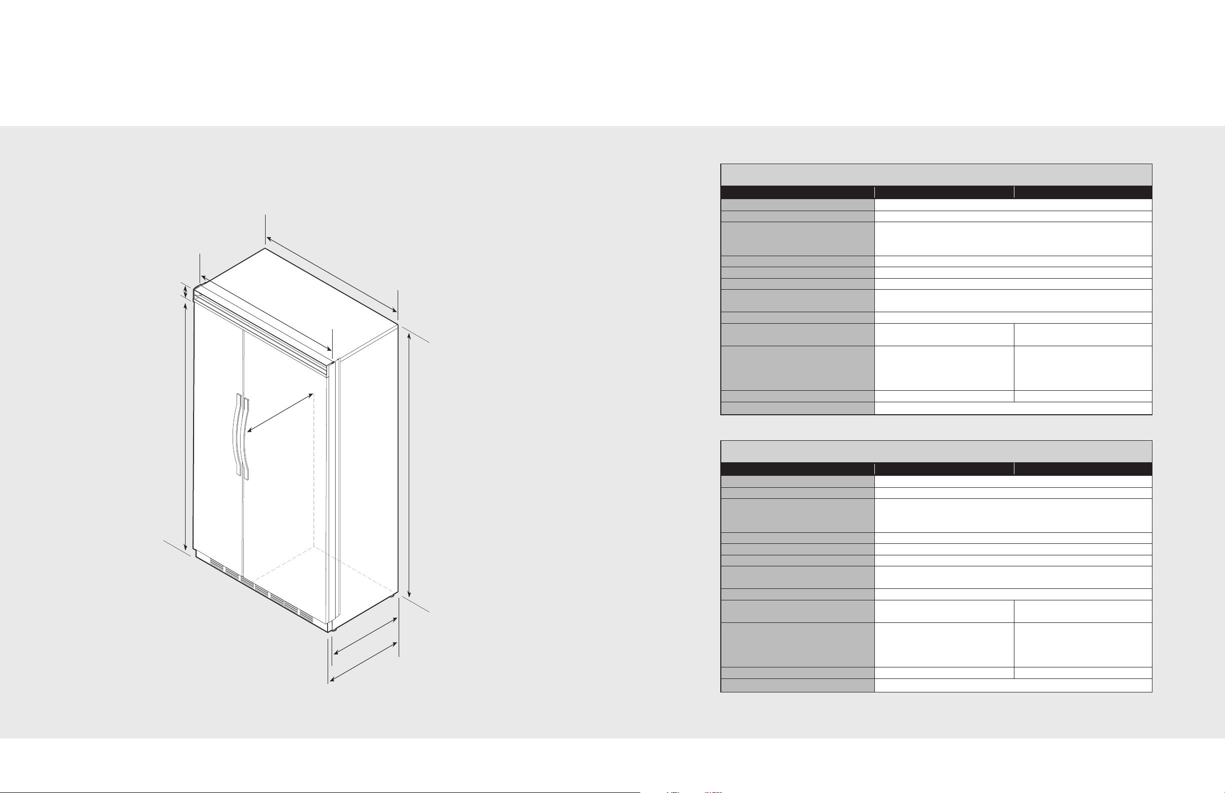
Dimensions (Side-By-Side)
Specifications (Side-By-Side)
48” Side-By-Side
42” Side-By-Side
Description DFSB423 DFSB423D
verall width 42” (106.7 cm)
O
Overall height (from bottom) 82-3/4” (210.2 cm) min. to 84-1/16” (213.5 cm) max.
Overall depth (from rear) To front edge of side trim: 23-13/16” (60.5 cm)
To front of top grille: 24-3/4” (62.9 cm)
To front edge of door trim: 24” (61.0 cm)*
Cutout width 42” (106.7 cm)
Cutout height 82-7/8” (210.5 cm) min. to 84-1/16” (213.5 cm) max.
Cutout depth 24” (61.0 cm) min.*
Electrical requirements 115 volt, 60 Hz, 15 amp dedicated circuit; 3-wire cord with
grounded 3-prong plug attached to product
Maximum amp usage 9.9 amps
Inlet water
requirements
Overall interior dimensions
Refrigerator 15.0 cu. ft. (425 liters) 14.5 cu. ft. (411 liters)
Freezer 9.0 cu. ft. (255 liters) 8.6 cu. ft. (244 liters)
Total capacity 24.0 cu. ft. (680 liters) 23.1 cu. ft. (654 liters)
Maximum panel weight Fresh food 40 lbs. (18.1 kg) Freezer 35 lbs. (15.9 kg)
Approximate shipping weight 525 lbs. (236.2 kg)
1/4” copper tubing inlet waterline; 1/4” copper tubing inlet waterline;
minimum 20 psi; maximum 120 psi minimum 35 psi; maximum 120 psi
48” Side-By-Side
Description DFSB483 DFSB483D
Overall width 48” (121.9 cm)
Overall height (from bottom) 82-3/4” (210.2 cm) min. to 84-1/16” (213.5 cm) max.
Overall depth (from rear) To front edge of side trim: 23-13/16” (60.5 cm)
To front of top grille: 24-3/4” (62.9 cm)
To front edge of door trim: 24” (61.0 cm)*
Cutout width 48” (121.9 cm)
Cutout height 82-7/8” (210.5 cm) min. to. 84-1/16” (213.5 cm) max
Cutout depth 24” (61.0 cm) min.*
Electrical requirements 115 volt, 60 Hz, 15 amp dedicated circuit; 3-wire cord with
grounded 3-prong plug attached to product
Maximum amp usage 9.9 amps
Inlet water
1/4” copper tubing inlet waterline; 1/4” copper tubing inlet waterline;
requirements minimum 20 psi; maximum 120 psi minimum 35 psi; maximum 120 psi
Overall interior dimensions
Refrigerator 18.5 cu. ft. (524 liters) 17.9 cu. ft. (507 liters)
Freezer 8.9 cu. ft. (252 liters) 8.5 cu. ft. (241 liters)
Total capacity 27.4 cu. ft. (776 liters) 26.4 cu. ft. (748 liters)
Maximum panel weight Fresh food 50 lbs. (22.7 kg) Freezer 35 lbs. (15.9 kg)
Approximate shipping weight 650 lbs. (292.5 kg)
*Full overlay models fit flush in 25” (63.5 cm) deep cabinet openings. They can be installed in standard 24” (61.0 cm)
11
deep openings. The door faces and top grille will protrude 3/4” (1.9 cm) into the room.
12
One 2”x 4” mounting board
1-1/2” (3.8 cm) x 3-1/2” (8.9 cm)
Note: If unit is installed deeper than 24” (61.0 cm), then shim
behind the mounting board by the difference.
Bottom of anti-tip board is 3-7/8” (9.8 cm) below opening height.
Note: Top of unit must be placed firmly under anti-tip board.
Anti-tip location
79
-
3/8”
(2
0
1
.6
c
m)
mi
n
.
t
o b
ot
t
o
m
of
a
nt
i
-
t
i
p
b
o
a
rd
80
-
1/2”
(20
4.6
c
m)
ma
x.
t
o b
ot
t
o
m
of
a
nt
i
-
t
i
p
b
o
a
rd
35”
(
8
8
.9 cm
)
3
-1
/
2
”
(8.
9 c
m
)
1-1
/2
”
(3.
8 c
m)
9”
(
22
.
9
c
m
)
73-
3/
8”
(18
6.4
c
m)
82-
7/8”
(2
1
0
.5
c
m)
mi
n
.
a
n
t
i
-
t
ip
b
o
ar
d
&
o
p
en
ing
he
igh
t
8
4
-1
/1
6
”
(21
3
.
5
c
m)
ma
x.
an
t
i-t
ip
boa
r
d
&
ope
n
in
g h
e
ig
h
t
42”
(10
6.
7 c
m)
2
4”
(61
.
0 c
m
)
Electric outlet location
Water line entry area
42”
(1
0
6
.
7
c
m
)
6-
3
/4”
(
17
.1
cm)
7-
5
/
8”
(
1
9
.4
cm)
3”
(7.6
cm
)
5/8
”
(1.
5 c
m)
5/8
”
(1.
5 c
m)
10-
1/2”
(26
.7
cm)
5
/8
”
(1
.5
cm
)
10-
3/4
”
(27
.3
cm)
1
”
(
2.
5
cm
)
3-5
/8
”
(9.
2 c
m)
Opt
ion
al f
loo
r
wat
er
lin
e e
ntr
y
See
a
n
t
i
-
t
i
p
b
o
a
rd
in
s
t
a
l
la
t
io
n
6
”
(1
5
.
2
c
m)
9
”
(2
2
.
9
c
m)
Cutout Dimensions (Side-By-Side)
Anti-Tip Dimensions (Side-By-Side)
42” Side-By-Side
42” Side-By-Side
1413
One 2”x 4” mounting boards
1-1/2” (3.8 cm) x 3-1/2” (8.9 cm)
Note: If unit is installed deeper than 24” (61.0 cm), then shim
behind the mounting board by the difference.
Bottom of anti-tip board is 3-7/8” (9.8 cm) below opening height.
Note: Top of unit must be placed firmly under anti-tip board.
Anti-tip location
79
-
3/8”
(2
0
1
.6
c
m)
mi
n
.
t
o b
ot
t
o
m
of
a
nt
i
-
t
i
p
bo
a
rd
80
-
1/2”
(20
4.6
c
m)
ma
x.
t
o b
ot
t
o
m
of
a
nt
i
-
t
i
p
bo
a
rd
41”
(10
4
.
1
cm
)
3
-1
/
2
”
(8.
9 c
m
)
1-1
/2
”
(3.
8 c
m)
9”
(
22
.
9
c
m)
73-
3/
8”
(18
6.4
c
m)
8
2–
7/8”
(2
1
0
.5
c
m)
mi
n
.
a
n
t
i-
t
ip
b
o
ar
d
&
o
p
en
ing
he
igh
t
84–1
/16
”
(21
3
.
5
c
m)
ma
x.
an
t
i-
t
ip
boa
r
d
&
ope
n
in
g
h
e
ig
h
t
48”
(12
1.
9 c
m)
2
4”
(61
.
0 c
m
)
Electric outlet location
Water line entry area
47-
1/
2”
(1
2
0
.
7
c
m
)
6-
3
/4”
(
17
.1
cm
)
7-
5
/
8”
(
1
9
.4
cm)
3”
(7.6
cm
)
5/8
”
(1.
5 c
m
)
5/8
”
(1.
5 c
m)
10-
1/2”
(26
.7
cm)
5
/8
”
(1.
5
cm
)
10-
3/4
”
(27
.3
cm)
1
”
(
2.
5
cm
)
3-5
/8
”
(9.
2 c
m)
Opt
ion
al f
loo
r
wat
er
lin
e e
ntr
y
See
a
n
t
i
-
t
i
p
b
o
a
rd
in
s
t
a
l
la
t
io
n
6
”
(1
5
.
2
c
m)
9
”
(2
2
.
9
c
m)
Cutout Dimensions (Side-By-Side)
Anti-Tip Dimensions (Side-By-Side)
48” Side-By-Side
48” Side-By-Side
1615
2
8
-
5
/1
6
”
(7
1
.9
c
m
)
75
-
1/2”
(1
9
1
.
8
c
m
)
3/
4”
(1
.
9
c
m
)
1
8
-
11
/
1
6
”
(
4
7
.5
c
m
)
3/
4”
(1
.
9
c
m
)
2
8
-
5
/1
6
”
(7
1
.9
c
m
)
7
5
-
1
/
2
”
(19
1.
8
c
m
)
3
/
4
”
(1
.
9
c
m
)
1
8
-
11
/1
6
”
(4
7
.5
c
m
)
31
-
5/8”
(8
0
.3
c
m
)
10
-
11
/16”
(2
7
.
1
c
m
)
12
-
3/8”
(3
1
.4
c
m
)
3/4”
(1
.
9
c
m)
3-
5/32”
(8
.0 c
m
)
22
-
13
/16
”
(5
7
.9
cm
)
7
5-
1
/2
”
(1
9
1
.
8
c
m)
3
/
4
”
(1
.
9
c
m
)
3
/
4
”
(1
.
9
c
m
)
18-
3/
1
6”
(
4
6
.2
c
m
)
22
-1
3
/16
”
(5
7
.9
c
m
)
7
5
-
1/2”
(1
9
1.
8
c
m
)
3
/4
”
(1
.
9
cm
)
18-
3/16”
(4
6
.2
c
m
)
3
1-
5
/8
”
(8
0
.3
c
m)
1
0-
1
1
/1
6
”
(2
7
.
1
c
m
)
1
2-
3
/8
”
(3
1
.4
c
m
)
3
/4
”
(1
.
9
cm
)
3
-5
/3
2
”
(8
.0 c
m
)
Overlay Dimensions(Side-By-Side)
Overlay Dimensions(Side-By-Side)
42” Custom Panels
42” Custom Panels
with Dispenser
48” Custom Panels
48” Custom Panels
with Dispenser
Note: Panel overlays must be dry, solid, straight
one piece panels. The use of multiple panel pieces
to achieve the dimensions is not recommended.
Important: A 1/4” thick back panel is required.
Make it 1/4” smaller than the dimensions shown.
Locate it to achieve a 1/8” inset on all sides.
17
Note: Panel overlays must be dry, solid, straight
one piece panels. The use of multiple panel pieces
to achieve the dimensions is not recommended.
Important: A 1/4” thick back panel is required.
Make it 1/4” smaller than the dimensions shown.
Locate it to achieve a 1/8” inset on all sides.
18
1
/2
”
(
1.
27
c
m
)
1/8”
(
.3
1 c
m)
1/
2”
(
1.
27
c
m
)
1
/
4
”
R
a
d
i
u
s
1/4” Radius
(
1
.
2
c
m
)
(1.2 cm)
1
/
4
”
R
a
d
i
u
s
(
.
6
4
c
m
)
Reverse dimensions
for other end.
7
/
8
”
(
2
.
2
2
c
m
)
1
/
2
”
(
1
.
2
7
cm
)
2
-
1
/8
”
(
5
.
3
9
c
m)
3
-
1
/8
”
(
7
.
9
4
c
m)
3
-
5
/
8
”
(
9
.
2
0
c
m
)
1
-
3
/
8
”
(
3
.
4
9
c
m
)
3
/
8
”
(
.
9
5
c
m)
3
/
8
” R
a
d
i
u
s
3/8” Radius
(
.
9
5
c
m
)
(.95 cm)
3
/
8
” R
a
d
i
u
s
(
.
9
5
c
m
)
4
7
-
1
/2
”
(12
0
.
6
5
c
m)
1
/2
”
(
1.
27
c
m
)
3
-
1
/
8
”
(
7
.
93
cm)
O
p
t
io
n
al
h
in
g
e c
o
v
er
4
6
”
(11
6
.
8
4
c
m
)
1
/2”
(
1.
2
7
c
m)
3
-5
/
8
”
(
9.
2
0
c
m)
4
5
-
1
5
/
1
6
”
(
1
1
6.
68
c
m
)
4
6
”
(
1
1
6.
84
c
m)
3
/4”
(
1.
9
0
c
m)
3
/4
”
(
1.
90
c
m)
3
-3
/
4
”
(
9.
5
2
c
m)
3
-3
/
4
”
(
9.
52
c
m)
3”
(
7.
6
2
cm
)
3
”
(
7.
62 cm)
3
/4
”
(
1.
9
0
c
m)
3
0
-
2
7
/3
2
”
(
7
8
.
3
4
c
m
)
3
2
-
3
/1
6
”
(
8
1
.
7
5
c
m
)
1
1
-1
7
/
32
”
(
2
9
.
2
8
c
m
)
1
0
-1
1
/
6
4
”
(
1
5
.
8
4
c
m
)
1
/
2
”
(
1
.
2
7
c
m)
1
-
1
/2
”
(
3
.
8
1
c
m
)
1
/
4
”
R
a
d
i
u
s
(.64
c
m
)
2
-
3
/4
”
(
6
.
98
c
m
)
1
/
2
”
(
1
.
2
7
c
m
)
3
/
4
”
(
1
.
9
0
c
m
)
1/
2
”
(
1.2
7 c
m)
1-
1/2
”
(
3
.
8
1
c
m
)
1/
4”
R
a
d
i
u
s
(
.
64
c
m
)
2-
3
/
4
”
(
6
.
98
c
m
)
1/
2”
(
1
.
2
7
c
m
)
3/
4”
(
1
.
9
0
c
m)
1/2
”
(1.
2
7
c
m
)
1/
8”
(
.
3
1 c
m
)
1
/
2
”
(1.
2
7
c
m
)
1/
4
”
R
a
d
iu
s
1/4” Radius
(
1
.
2
c
m)
(1.2 cm)
1/
4
”
R
a
d
iu
s
(
.
6
4
c
m)
Reverse dimensions
for other end.
7/8”
(2.
22
c
m
)
1/2
”
(1
.
27
c
m)
2-1
/8”
(5
.
3
9
c
m)
3-1
/8”
(7
.
9
4
c
m)
3-
5
/
8”
(9
.
2
0 c
m)
1-3
/8”
(3
.
4
9
cm
)
3/
8”
(.9
5
cm)
3/8
” R
ad
i
us
3/8” Radius
(.
9
5
c
m
)
(.95 cm)
3/8
” R
ad
i
us
(.
9
5
c
m
)
41
-1
/2
”
(1
0
5.
41
c
m)
1/2
”
(
1.
2
7
c
m)
3-
1/
8
”
(
7
.
9
3
cm)
Opt
ion
al
hing
e
c
ove
r
40”
(10
1
.6
0
cm)
40”
(
1
0
1.60
c
m)
3/4”
(
1.
9
0
c
m
)
3/4
”
(
1.
9
0
c
m
)
3-
1/
4”
(9.
5
2
c
m
)
3-
3/
4”
(
9.
5
2
c
m
)
1/2”
(
1.
2
7
c
m
)
3-
5/
8”
(
9.
2
0
c
m
)
39-
15/
16”
(
1
0
1.44
cm
)
3
”
(
7.
6
2
cm
)
3”
(7.
6
2
c
m
)
3/4
”
(
1.
9
0
c
m
)
24
-
27/
32
”
(63
.10
cm)
26
-
3/16”
(66
.51
cm)
5
-1
7/32
”
(
1
4
.
0
4
cm)
4-
1
1/
6
4”
(
1
0
.
6
0
c
m
)
Custom Grille Dimensions (Side-By-Side)
Custom Grille Dimensions (Side-By-Side)
42” Custom Grille 48” Custom Grille
19
20
 Loading...