


F20034K EN (022108J)
Viking Range Corporation
111 Front Street
Greenwood, Mississippi 38930 USA
(662) 455-1200
For more product information,
call 1-888-VIKING1 (845-4641)
or visit the Viking Web site at
vikingrange.com
Viking Installation Guide
Built-In Electric Cooktop
2
IMPORTANT: PLEASE READ AND FOLLOW
•Before beginning, please read these instructions completely and carefully.
•Do not remove permanently affixed labels, warnings, or plates from the product. This may void the warranty.
•Please observe all local and national codes and ordinances.
•Please ensure that this product is properly grounded.
•The installer should leave these instructions with the consumer who should retain for local inspector’s use and for future
reference.
•Installation must conform with local codes or, in the absence of codes, the National Electrical Code, ANSI/NFPA 70-latest edition.
IN CANADA: Electrical installation must be in accordance with the current CSA C22.1 Canadian Electrical Codes Part 1
and/or local codes.
GENERAL INFORMATION
1. WARNING: The use of cabinets for storage above the appliance may result in potential burn hazard. Combustible
items may ignite, metallic items may become hot and cause burns. If a cabinet storage is to provided the risk can be
reduced by installing a range hood that projects horizontally a minimum of 5 in. beyond the bottom of the cabinets.
2. WARNING: This appliance shall not be used for space heating. This information is based on safety considerations.
3. All openings in the wall behind the appliance in the floor under the appliance shall be sealed.
4. Keep appliance area clear and free from combustible materials, gasoline, and other flammable vapors.
5. Disconnect the electric supply to the appliance before cleaning or servicing.
6. When removing the cooktop for service and/or cleaning, disconnect AC power supply.
7. Electrical Requirement: Listed on Specifications - Minimum Recommended Electric Circuit.
ELECTRICAL GROUNDING INSTRUCTIONS
This cooktop must be electrically grounded in accordance with local codes or, in the absence of
codes, with the National Electrical Code,
ANSI/NFPA 70-latest edition.
3
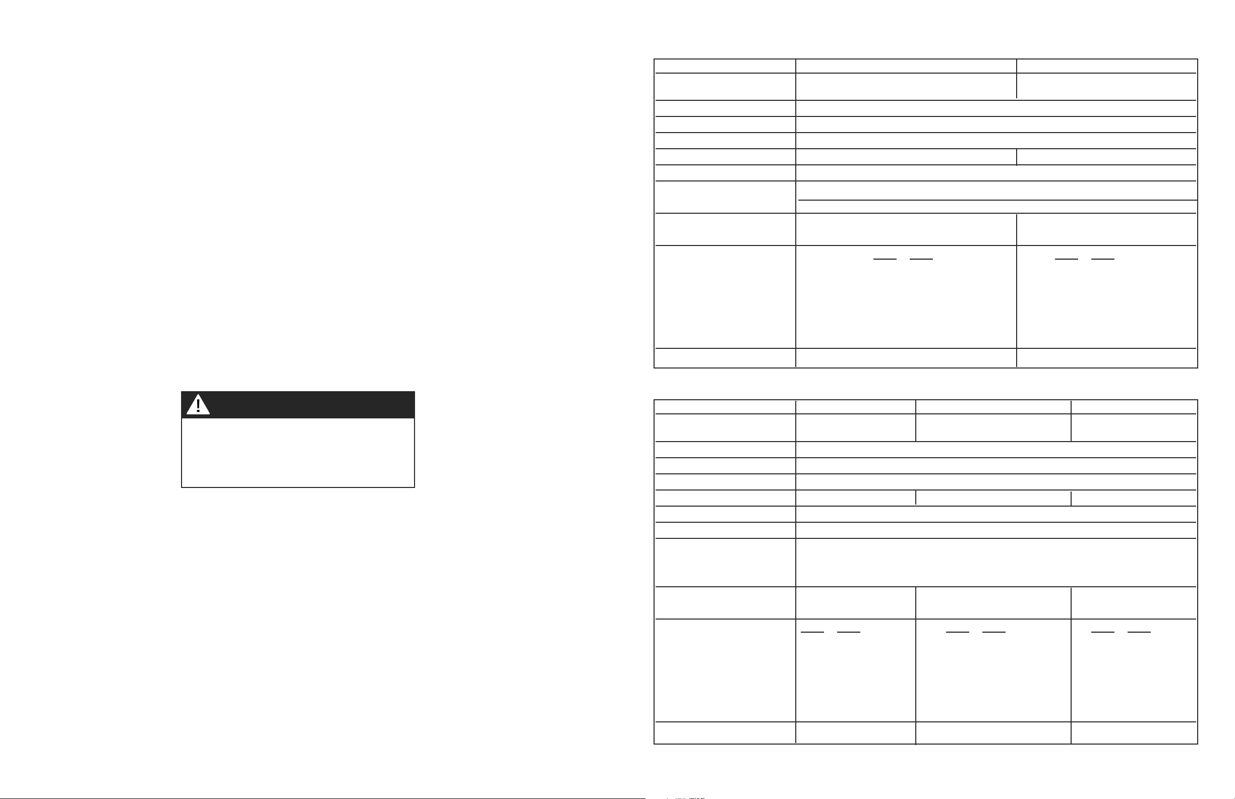
Description DECU106 30” W. DECU166 36” W. DECU155 45” W.
Cutout Width Minimum 28 5/8” (72.7 cm) 34 3/4” (88.3 cm) 42 7/8” (108.9 cm)
Maximum 29 7/8” (75.9 cm) 35 7/8” (91.1 cm) 44 1/8” (112.1 cm)
Cutout Height Minimum 3 1/8” (7.9 cm)
Cutout Height with Conduit 4 1/8” (10.5 cm)
Cutout Depth Minimum 19 3/4” (50.2 cm) Maximum - 20 1/8” (51.1 cm)
Overall Width 30 3/4” (78.1 cm) 36 3/4” (93.3 cm) 45” (114.3 cm)
Overall Height from Bottom 4 1/2” (11.4 cm)
Overall Depth from Rear 21” (53.3 cm)
Electrical Requirements 240 - 208/120 VAC/60 Hz - 3-wire conduit with a No. 10 ground wire. Connect with lo-
cally supplied 3-wire with ground, flexible cord rated 60 amp 125-250 VAC minimum.
Cord must be agency approved for use with household electric cooktops.
Maximum Amp Usage 240V 8.4 kW; 35.0 amps 10.9 kW; 44.0 amps 11.8 kW: 49.0 amps
208V 6.3 kW; 30.0 amps 8.2 kW; 34.0 amps 8.9 kW; 43.0 amps
Surface Element Rating 240V 208V 240V 208V 240V 208V
Right Front 1500 1125 watts 1500 1125 watts 1500 1125 watts
Right Rear 2500 1875 watts 2200 1650 watts 2200 1650 watts
Center Right N/A N/A 2500 1875 watts 1200 900 watts
Center Left N/A N/A N/A N/A 2500 1875 watts
Left Front 1800 1350 watts 1800 1350 watts 1800 1350 watts
Bridge 800 600 watts 800 600 watts 800 600 watts
Left Rear 1800 1350 watts 1800 1350 watts 1800 1350 watts
Approximate Shipping Weight 52 lb. (23.4 kg) 60 lb. (27.0 kg) 71 lb. (32.0 kg)
SPECIFICATIONS - DECU ELECTRIC COOKTOP
Description VECU106 30” W. VECU166 36” W.
Cutout Width Minimum 28 3/4” (73.0 cm) Minimum 34 3/4” (88.3 cm)
Maximum 29 5/8” (75.2 cm) Maximum 35 1/2” (90.2 cm)
Cutout Height Minimum - 3 1/8” (7.9 cm)
Cutout Depth Minimum - 19 1/8” (48.6 cm) Maximum - 19 7/8” (50.5 cm)
Overall Width 30 3/4” (78.1 cm) 36 3/4” (93.3 cm)
Overall Height from Bottom 5” (12.7 cm)
Overall Depth from Rear 21” (53.3 cm)
Electrical Requirements 240 - 208/120 VAC/60 Hz - 3-wire conduit with a No. 10 ground wire.
40 amp connection 60 amp connection
Maximum Amp Usage 240V 8.4 kW; 35.0 amps 11.8 kW 49.2 amps
208V 6.3 kW; 30.3 amps 8.9 kW 42.6 amps
Surface Element Rating 240V 208V 240V 208V
Right Front 1500 1125 watts 1200 900 watts
Right Rear 2500 1875 watts 2500 1875 watts
Center Front N/A N/A 1800 1350
Bridge 800 600 watts 800 600 watts
Center Rear N/A N/A 1800 1350
Left Front 1800 1350 watts 2200 1650 watts
Left Rear 1800 1350 watts 1500 1125 watts
Approximate Shipping Weight 52 lb. (23.4 kg) 63 lb. (28.4 kg)
SPECIFICATIONS - VECU ELECTRIC COOKTOP
WARNING!
4
ELECTRICAL REQUIREMENTS
Check your local codes regarding this unit. This cooktop is supplied with a 3-wire, A.C. 208/120 volt or 120/240 volt, 60
HZ electrical system. A white (neutral) is not needed for this unit. See next section for grounding instructions. It should
be fused separately. CAUTION: Be sure the electric power is off from the breaker box to the junction box until the
cooktop is installed and ready to operate. The junction box should be connected to a suitable ground. Do not use a
GFI circuit.
Refer to the sepcifications chart and the identification label on the bottom of the burner box for kilowatt rating and recommended amperage. House wiring and fusing must comply with local codes. If no local codes are applicable, wire in
accordance with the National Electrical Code, ANSI/NFPA 70-latest edition.
ELECTRICAL CONNECTION
WARNING: The electrical power to the unit must be shut off while line connections are being made. Failure to
do so could result in serious injury or death.
When making the wire connections, use the entire length of the conduit provided (3 feet). The conduit must not be cut.
Connect the red and black leads from the unit conduit to the corresonding leads in the junction box. The green ground
wire in the conduit is connected to the unit frame. When connecting to a 3-conductor branch circuit, if local codes permit, connect the green ground connector lead of the unit to the branch circuit neutral (gray or white in color).
DO NOT USE AN EXTENSION CORD WITH THIS APPLIANCE. SUCH USE MAY
RESULT IN A FIRE, ELECTRICAL SHOCK OR OTHER PERSONAL INJURY.
5
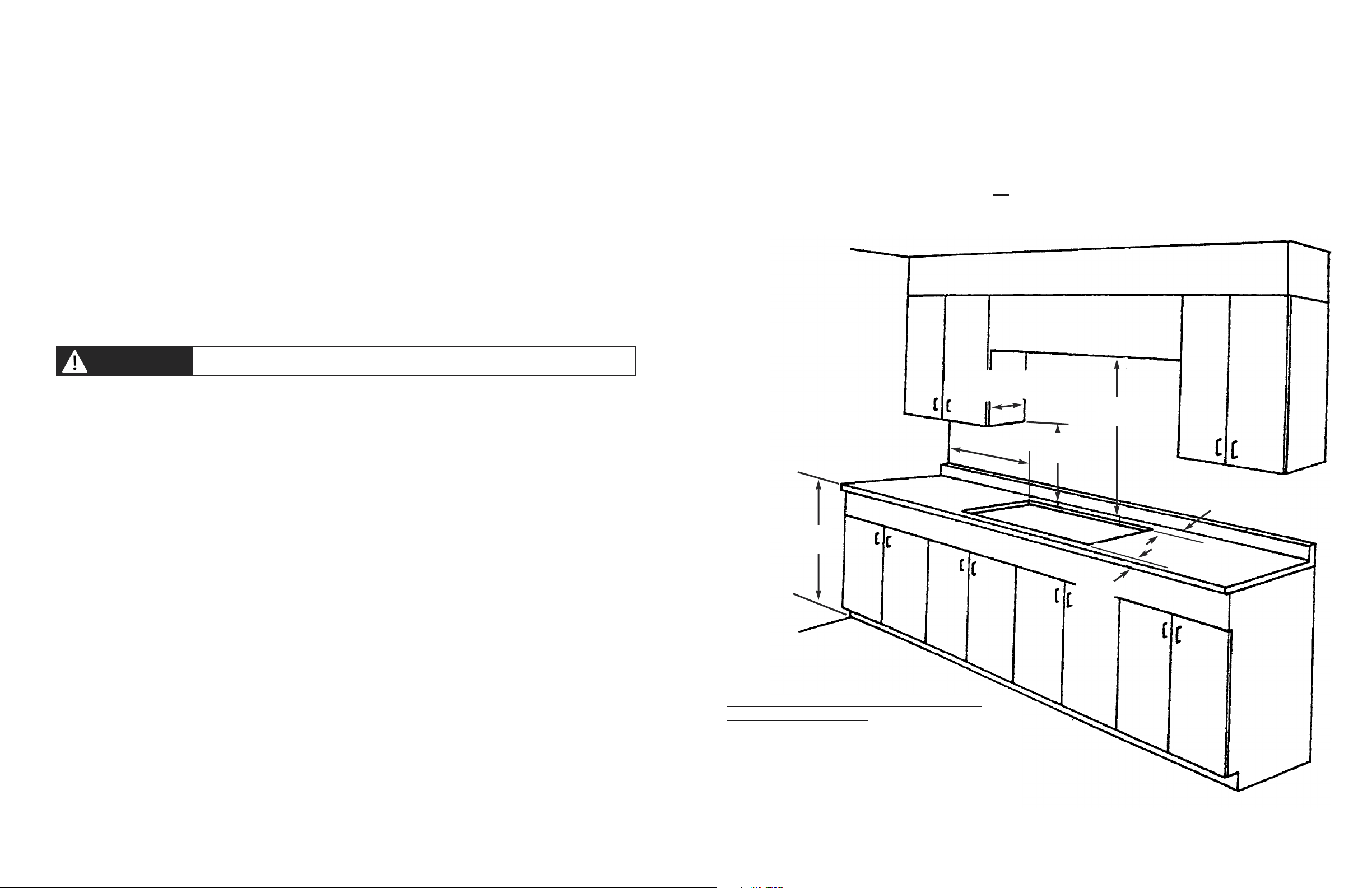
PROXIMITY TO SIDE CABINET INSTALLATION
1. The cooktop may be installed directly to existing base cabinets.
2. The cooktop CANNOT be installed directly adjacent to sidewalls, tall cabinets, tall appliances, or other side vertical
surfaces above 36” (91.4 cm) high. There must be a minimum of 6” (15.2 cm) side clearance from the cooktop to
such combustible surfaces above the 36” (91.4 cm).
3. Within the 6” (15.2 cm) side clearance to combustible vertical surfaces above 36” (91.4 cm), the maximum wall cabinet depth must be 13” (33.0 cm) and wall cabinets within this 6” (15.2 cm) side clearance must be 18” (45.7 cm)
above the 36” (91.4 cm) high countertop.
4. Wall cabinet above the cooktop must be a minimum of 36” (91.4 cm) above the countertop for a full width of the
cooktop. This minimum height requirement does not apply if a rangehood is installed over the cooking surface.
NOTE: Refer to Installation of Hold Down Brackets on pages 9 and 13 for minimum clearances under counter.
MINIMUM CLEARANCES FROM ADJACENT COMBUSTIBLE CONSTRUCTION
•Above countertop (above 36” [91.4 cm])
•Side 6” (15.2 cm)
•Rear 0” (0 cm)
•Within 8” side clearance. Wall cabinets no deeper
than 13” (33.0 cm)
•Must be minimum 18” (45.7 cm) above countertop
•Wall cabinets directly above the product must be
minimum 36” (91.4 cm) above the countertop.
13” Max
(33.0 cm)
36” Min.
(91.4 cm)
6” Min.(15.2 cm)
18” Min.
(45.7 cm)
36” Min.
(91.4 cm)
3 1/8”
(7.9 cm)
0” Min.
(0 cm)
WARNING!
 Loading...