


INSTALLATION
INSTRUCTIONS
AND SAFETY INFORMATION
FOR THE VIKING Q-7 GATE OPERATOR
CLASS II, CLASS III, AND CLASS IV
Heavy-Duty Commercial
Vehicular Slide Gate Operator
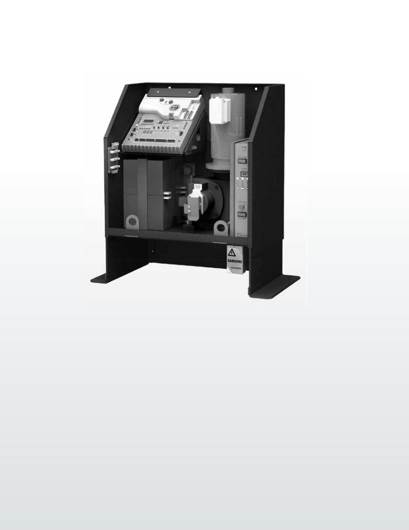
The Q-7™ gate operator has the capacity to operate slide gates up to 7000 lbs. and 120 ft. in length at 100% duty cycle under extreme conditions. This effi cient operator provides a solution for high traffi c commercial and industrial slide gate applications. The Viking Q-7™ gate operator offers effi ciency and technology combined in a single package.
THE VIKING Q-7™ SLIDE GATE OPERATOR

Q-7 Vehicular Gate Operator • Revision Q7NXMN10.E • December 2013

PARTS DIAGRAM:
Item |
Description |
Part No. |
1 |
Chassis |
VAQ7CH10 |
2 |
Chassis Top Cover |
VAQ7CHTC10 |
3 |
Q7 Cover Lock (2) |
VAQ7CL |
4 |
Chassis Front Cover |
VAQ7CHFC10 |
5 |
Chain Guard |
VAQ7CHCG10 |
6 |
Q7 J-Box Cover |
VAQ7JBC |
7 |
Battery |
DUBA35 |
8 |
Loop Rack |
VA-LR |
9 |
Control Board |
VFLEXPCB-Q7 |
10 |
Fuse - 4 amp |
VNXF4A |
11 |
Fuse - NOT USED |
N/A |
12 |
Release Handle |
VNXQ7RH |
13 |
Manual Release Sensor |
DNXTS10 |
14 |
Q7 Gearbox |
Q7GB70 |
15 |
Q7 Motor |
VAQ7MO |
16 |
Brush Kit |
VAQ7MBK |
17 |
Electronic Positioning Sensor 2 (EPS2) |
VNXSLEPS2 |
18 |
Motor Breaker |
VAQ7MB20 |
19 |
Chain #50 x 10’ x 3 |
Q4C50CHK |
20 |
23B50 Sprocket |
Q7SP50 |
21 |
Idler Pulley |
VAQ4IP |
22 |
Idler Pulley Bushing |
VNXQ7IB20 |
23 |
Alarm |
DUAL10 |
24 |
Battery Switch |
DUMRS20 |
25 |
Q7 Power Box Assembly |
VNXQ7PBA |
26 |
Receptacle 120V |
DUOL120 |
27 |
Motor Power Switch |
DUMRS10 |
28 |
EMI Board |
VNXDUEMI |
29 |
AC Power Switch |
DUMRS20 |
30 |
EMI Fuse Holder & Harness |
VNXEFHH |
31 |
Fuse - 8 amp |
DUF8EMI |
32 |
Toroidal Transformer - 15 amp |
DUTT15 |
33 |
Motor Harness |
VNXQ7MH |
34 |
Power Harness |
VAQ7PH |
2 |
VIKING TECHNICAL SUPPORT 1.800.908.0884 |
|
|
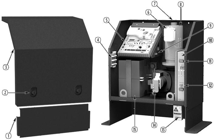
OPERATOR REFERENCES:
1.FRONT COVER
2.COVER LOCK (2)
3.TOP COVER
4.LOOP RACK
for convenient loop detector installation
5.VFLEX CONTROL BOARD
6.MOTOR BREAKER
resetable; protects the motor circuitry
7.EPS2 (ELECTRONIC POSITIONING SENSOR) sensor for the digital limits
8.MOTOR
9.BATTERY SWITCH
disconnects batteries from the charging circuit during troubleshooting
10.POWER BOX ASSEMBLY
removable; convenient access to the power supply components
11.MOTOR POWER SWITCH
switch & breaker; provides additional protection for the motor circuitry .
12.EMI FUSE
main power supply protection
13.J-BOX
high voltage power supply connection
14.MANUAL RELEASE HANDLE convenient mechanical gear release
15.BATTERY BACKUP SYSTEM
backup power supply in case of power outage; 24V/35Ah
VIKING TECHNICAL SUPPORT 1.800.908.0884 |
3 |
|
|

CONTROL BOARD REFERENCES:
1.POWER HARNESS CONNECTOR provides power to the control board. pg 18-19
2.“OPEN LEFT” & “OPEN RIGHT” provides power to the motor. pg 20
3.LIMIT SETUP BUTTONS
sets limit positions. pg 20-21
4.FEATURE ACTIVATION TRIM POTS activate and set features. pg 24
5.“EPS1” CONNECTOR
monitors manual release operation.
6.“EPS2” CONNECTOR monitors the limit positions.
7.EMI BOARD CONNECTOR
monitors the high voltage power supply.
8.“CHECK MOTOR” Status LED indicates motor power status. pg 36
9.“BATTERY LOW” Status LED
indicates battery power status. pg 36
10.“POWER” Status LED
control board power status. pg 18,36
11.“MAGNETIC LOCK RELAY” Status LED status of this on-board relay. pg 34, 36
12.“MAGNETIC LOCK RELAY” Terminal Block connect electric locks here. pg 34, 36
13.INPUT STATUS LEDs
indicates input status. pg 36-37
14.ACCESS CONTROL TERMINAL BLOCKS accessory connections. pg 29-32, 42-44
15.“MASTER/SLAVE” Terminal Block wired master/slave connection. pg 22
16.CONTROL BOARD MOUNTING HOLES secures and grounds the control board.
17.“Siren” Terminal Block
Vikings UL Siren is connected here.
18.ON-BOARD 3 BUTTON STATION controls the gate during set up.
19.“AUX PWR” Terminal Block
used for solar applications & in-motion warning devices. pg 19, 25
20.FEATURE ACTIVATION PIN HEADERS activate features by placing a jumper onto the pin headers. pg 25
21.“DIAGNOSE” Button
allows you to navigate through the Diagnostics LCD Display. pg 38-40
22.“DIAGNOSE” LED
informs that errors have been detected and available on LCD Display. pg 38-40
23.LCD DIAGNOSTICS DISPLAY
provides error messages, diagnostics settings and operator status information. pg 38-40
24.EXPANSION PRODUCT CONNECTIONS connections for additional products from Viking Access Systems. pg 46
25.“FAIL SAFE/SECURE” Jumper
not applicable to this model.
26.NOT USED
27.FUSE HOLDER - 4 AMP for charging circuit.
28.HEAT SINK
secures the control board and dissipates heat.
4 |
VIKING TECHNICAL SUPPORT 1.800.908.0884 |
|
|

|
|
|
|
|
TABLE OF CONTENTS: |
|||||||||||||||
|
|
|
|
|
|
|
|
|
|
|
|
|
|
|
|
|
|
|
|
|
|
|
PARTS DIAGRAM/PARTS LIST |
||||||||||||||||||
|
|
2 |
||||||||||||||||||
|
|
|
|
|
|
|
|
|
|
|
|
|
|
|
|
|
|
|
||
OPERATORREFERENCES |
||||||||||||||||||||
|
|
3 |
||||||||||||||||||
|
|
|
|
|
|
|
|
|
|
|
|
|
||||||||
|
CONTROL BOARD REFERENCES |
|
|
|
|
|
||||||||||||||
|
|
4 |
|
|
|
|
|
|
||||||||||||
|
|
|
|
|
|
|
|
|
|
|||||||||||
|
|
IMPORTANTSAFETYINFORMATION |
|
6-12 |
|
|
|
|||||||||||||
|
|
Important Safety Instructions |
6 |
|
|
|
|
|
||||||||||||
|
|
Important Installation Instructions |
7 |
|
|
|
|
|
||||||||||||
|
|
Maintenance |
8 |
|
|
|
|
|
||||||||||||
|
|
General Safety Precautions |
8-9 |
|
|
|
|
|||||||||||||
|
|
Operator Classification |
9 |
|
|
|
|
|
||||||||||||
|
|
Photo Beam (non-contact sensor) Installation |
10 |
|
|
|
|
|||||||||||||
|
|
Edge Sensor (contact sensor) Installation |
11 |
|
|
|
|
|
||||||||||||
|
|
Manual Release |
11 |
|
|
|
|
|
||||||||||||
|
|
Audible Alarm Reset Installation |
12 |
|
|
|
|
|||||||||||||
|
|
Warning Placard Installation |
12 |
|
|
|
|
|||||||||||||
|
|
|
|
|
|
|
|
|
|
|
|
|
|
|
|
|
|
|||
|
|
IMPORTANT INSTALLATION INFORMATION |
||||||||||||||||||
|
|
13 |
||||||||||||||||||
|
|
Specifications |
13 |
|
|
|
|
|||||||||||||
|
|
|
|
|
|
|
|
|
|
|
|
|
|
|
|
|
||||
GATE |
||||||||||||||||||||
|
|
14-17 |
|
|
||||||||||||||||
|
|
Concrete Pad Installation |
14 |
|
|
|
|
|||||||||||||
|
|
Positive Stop Installation |
15 |
|
|
|
|
|||||||||||||
|
|
Operator Positioning |
16-17 |
|
|
|||||||||||||||
|
|
|
|
|
|
|
|
|
|
|
|
|
|
|
|
|
|
|
|
|
|
|
ELECTRICALINSTALLATION18-19 |
|
|
|
|
|
|
|
|
|
|
|
|
|
|
||||
|
|
High Voltage Supply Option |
18 |
|
|
|
|
|||||||||||||
|
|
Solar Supply Option |
19 |
|
|
|
|
|||||||||||||
|
|
|
|
|
|
|
|
|
|
|
|
|
|
|
|
|
|
|
|
|
|
|
LIMITS20SETUP-21 |
|
|
|
|
|
|
|
|
|
|
|
|
|
|
||||
|
|
|
|
|
|
|
|
|
|
|
|
|
|
|
|
|
|
|
|
|
|
|
MASTER/SLAVE SET UP |
|
|
|
|
|
|
|
|
|
|
|
|
|
|
||||
|
|
|
|
|
|
|
|
|
|
|
|
|
|
|
|
|
|
|||
|
|
Two Wire Communication |
22 |
|
|
|
|
|||||||||||||
|
|
Wireless Communication Options |
23 |
|
|
|
|
|||||||||||||
|
|
|
|
|
|
|
|
|
|
|
|
|
|
|||||||
CONTROL BOARD SETUP |
24-27 |
|
|
|
|
|||||||||||||||
|
|
Initial Settings |
24-25 |
|||||||||||||||||
|
|
Obstruction Detection Sensor (Primary Entrapment Protection) |
26 |
|
|
|
|
|||||||||||||
|
|
Heater, Lock Mode................................................................................................................. 27 |
||||||||||||||||||
|
|
|
|
|
|
|
|
|
|
|
|
|
|
|
|
|
||||
ACCESSORYCONNECTIONS29-35 |
|
|
|
|
|
|
|
|
|
|
|
|
|
|
||||||
|
|
Re-Open Photo Beam (Vehicular Safety) |
29 |
|
|
|
|
|||||||||||||
|
|
Radio Receiver (Typical) |
30 |
|
|
|
|
|||||||||||||
|
|
Anti-Tailgate, Open Commands, Guard Station |
31 |
|
|
|
|
|||||||||||||
|
|
Viking Loop Rack |
32 |
|
|
|
|
|||||||||||||
|
|
Guidelines for Loop Installations |
33 |
|
|
|
|
|||||||||||||
|
|
Magnetic Lock, Lock Solenoid |
34 |
|
|
|
|
|||||||||||||
|
|
Barrier Arm (B-12) Synchronization Option |
35 |
|
|
|
|
|||||||||||||
|
|
|
|
|
|
|
|
|
|
|
|
|
||||||||
TROUBLESHOOTING |
|
|
||||||||||||||||||
|
|
|
|
36-41 |
|
|
||||||||||||||
|
|
LED References |
36-37 |
|
||||||||||||||||
|
|
LCD Display References |
38-40 |
|||||||||||||||||
|
|
Solutions |
41 |
|
|
|
|
|
||||||||||||
APPENDIX A, B & C 42-45
VIKING EXPANSION PRODUCTS 46
VIKING TECHNICAL SUPPORT 1.800.908.0884 |
5 |
|
|

IMPORTANT SAFETY INFORMATION
! WARNING! Not Following these instructions may cause severe injury or death.
IMPORTANT SAFETY INSTRUCTIONS
! WARNING! To reduce the risk of severe injury or death.
1. READ AND FOLLOW ALL INSTRUCTIONS.
2.Never let children operate or play with gate controls. Keep the remote away from children.
3.Always keep people and objects away from the gate. NO ONE SHOULD CROSS THE PATH OF THE MOVING GATE.
4.Test the gate operator monthly. The gate MUST reverse on contact with a rigid object or when an object activates the non-contact sensors. After adjusting the force or the limit travel, retest the gate operator. Failure to
adjust and retest the gate operator properly can increase the risk of injury or death.
5. Use the emergency release only when the gate is not moving.
6.KEEP GATES PROPERLY MAINTAINED. Read the user’s manual. Have a qualified service person make repairs to gate hardware.
7.The entrance is for vehicles only. Pedestrians must use a separate entrance.
8. Every gate operator installation MUST have secondary protection devices against entrapment, such as edge sensors and photo beams more in particularly in places where the risk of entrapment is more likely to occur.
9. SAVE THESE INSTRUCTIONS.
IMPORTANT INSTALLATION INSTRUCTIONS
1. Install the gate operator only when:
a.The operator is appropriate for the construction of the gate and usage Class of the gate (refer to page 9),
b.All openings of a horizontal slide gate are guarded or screened from the bottom of the gate to a minimum of 6 feet (1.83 m) above the ground to prevent a 2-1/4 inch (57.2 mm) diameter sphere from passing through the openings anywhere in the gate, and in that portion of the adjacent fence that the gate covers in the open position,
c.ALL EXPOSED PINCH POINTS ARE ELIMINATED OR GUARDED, AND
d.GUARDING IS SUPPLIED FOR EXPOSED ROLLERS.
2.The Operator is intended for installation only on gates used for vehicles. Pedestrians must be supplied with a separate access opening. The pedestrian access opening shall be designed to promote pedestrian usage. Locate the gate such that persons will not come into contact with the vehicular gate during the entire path of travel of the vehicular gate.
3.The gate must be installed in a location so that enough clearance is supplied between the gate and adjacent structures when opening and closing to reduce the risk of entrapment. Swinging gates shall not open in to the public access areas.
4.The gate must be properly installed and work freely in both directions prior to the installation of the gate operator. Do not over-tighten the operator clutch or pressure relief valve to compensate for a damaged gate.
5. The gate operator controls must be placed so that the user has full view of the gate area when the gate is moving AND AWAY FROM THE GATE PATH PERIMETER.
6 |
VIKING TECHNICAL SUPPORT 1.800.908.0884 |
|
|

IMPORTANT SAFETY INFORMATION
! WARNING! Not Following these instructions may cause severe injury or death.
IMPORTANT INSTALLATION INSTRUCTIONS (Continued)
6.Controls intended for user activation must be located at least six feet (6’) away from any moving part of the gate and where the user is prevented from reaching over, under, around or through the gate to operate the controls.
Exception: Emergency access controls only accessible by authorized personnel (i.g. fire, police, EMS) may be placed at any location in the line-of-sight of the gate.
7.The Stop and/or Reset button must be located in the line-of-sight of the gate. Activation of the reset control shall not cause the operator to start.
8.A minimum of two (2) WARNING SIGNS shall be installed, one on each side of the gate where easily visible.
9.For gate operators using non-contact sensors (Photo Beams or like) in accordance with section 31.1.1 of the UL standard:
a.See instructions on the placement of non-contact sensors for each type of application (refer to page 10).
b.Care shall be exercised to reduce the risk of nuisance tripping, such as when a vehicle, trips the sensor while the gate is still moving, and
c.One or more non-contact sensors shall be located where the risk of entrapment or obstruction exists, such as the perimeter reachable by a moving gate or barrier (refer to page 10).
d.Use only Omron E3K-R10K4 photoelectric eye to comply with UL 325
10.For a gate operator utilizing a contact sensor (Edge sensor or like) in accordance with section 31.1.1 of the UL 325 standard:
a.One or more contact sensors shall be located where the risk of entrapment or obstruction exists, such as a the leading edge, trailing edge, and post mounted both inside and outside of a vehicular horizontal slide gate (refer to page 11).
b.One or more contact sensors shall be located at the bottom of a vehicular vertical lift gate.
c.One or more contact sensors shall be located at the pinch point of a vehicular vertical pivot gate.
d.A hardwired contact sensor shall be located and its wiring arranged so that the communication between the sensor and the gate operator is not subject to mechanical damage.
e.A wireless contact sensor such as one that transmits radio frequency (RF) signals to the gate operator for entrapment protection functions shall be located where the transmission of the signals are not obstructed or impeded by building structures, natural landscaping or similar obstructions. A wireless contact sensor shall function under the intended end-use conditions.
f.One or more contact sensors shall be located on the inside and outside leading edge of a swing gate. Additionally, if the bottom edge of a swing gate is grater than 6 inches (152 mm) above the ground at any point in its arc of travel, one or more contact sensors shall be located at the bottom.
g.One or more contact sensors shall be located at the bottom edge of a vertical barrier (arm).
h.Only Use Miller Edge Model MGR20 or MGS20 edge sensor to comply with UL325.
VIKING TECHNICAL SUPPORT 1.800.908.0884 |
7 |
|
|

IMPORTANT SAFETY INFORMATION
! WARNING! Not Following these instructions may cause severe injury or death.
MAINTENANCE
Remove the Power Harness from the Control Board. (refer to page 18)
•Clean and lubricate the gate track wheels using the recommended lubricant.
•Inspect the track for any signs of cracking or separation.
•Check that all mounting hardware of the gate operator is properly tighten.
•Ensure that the gate moves freely.
•Check for corroded parts and replace if necessary.
•Check the battery for the following:
-Battery connections must be free of corrosion.
-Battery voltage must be 26VDC (fully charged battery).
Reconnect the Power Harness for the Control Board. (refer to page 18)
•Check and confirm the proper operation of all safety devices (photoelectric eye, edge sensors or like).
•Check and confirm the operation of all installed accessories.
•Check and confirm the operation of all special features such as the Intelligent
Obstruction Sensor, Hold Open Timer. (refer to page 24 and 26)
•Check and confirm the operation of the manual release. (refer to page 7)
•Verify the functionally of the battery backup, or power failure option, by turning off the main power source (115VAC or 230VAC). DO NOT FORGET TO
TURN ON THE MAIN POWER SOURCE AFTER VERIFICATION.
GENERAL SAFETY PRECAUTIONS
The following precautions are an integral and essential part of the product and must be supplied to the user. Read them carefully as they contain important indications for the safe installation, use and maintenance.
•These instruction must be kept and forwarded to all possible future users of the system.
•This product must be used only for that which it has been expressly designed.
•Any other use is to be considered improper and therefore dangerous.
•The manufacturer cannot be held responsible for possible damage caused by improper, erroneous or unreasonable use.
•Avoid operating in the proximity of the hinges or moving mechanical parts.
•Do not enter the path of the moving gate while in motion.
•Do not obstruct the motion of the gate as this may cause a situation of danger.
•Do not allow children to play or stay within the path of the moving gate.
•Keep remote control or any other control devices out of the reach of children, in order to avoid possible involuntary activation of the gate operator.
•In case of break down or malfunctioning of the product, disconnect from the main power source. Do not attempt to repair or intervene directly, contact only qualified personnel for repair.
•Failure to comply with the above may create a situation of danger.
•All cleaning, maintenance or repair work must be carried out by qualified personnel.
•In order to guarantee that the system works efficiently and correctly it is important to have the manufacturer’s instructions on maintenance of the gate and operator carried out by qualified personnel.
•In particular, regular checks are recommended in order to verify that the safety devices are operating correctly.
All installation, maintenance and repair work must be documented and made available to the user.
8 |
VIKING TECHNICAL SUPPORT 1.800.908.0884 |
|
|
IMPORTANT SAFETY INFORMATION
!CAUTION: To Reduce the Risk of Fire or Injury to Persons:
a.Use only the following type and size battery(ies): Yuasa NP7-12 or VIKING DUBA12
b.Do not dispose of the battery(ies) in fire. The cells may explode. Check with local codes for possible disposal instructions.
c.Do not open or mutilate the battery(ies). Released electrolyte is corrosive and may cause damage to the eyes or skin. It may be toxic if swallowed.
d.Exercise care in handling batteries in order not to short the battery with conducting materials such as rings, bracelets and keys.
e.Change the battery(ies) provided with or identified for use with this product only in accordance with the instructions and limitations specified in this manual.
f.Observe proper polarity orientation between the battery(ies) and charging circuit.
g.Do not mix batteries of differ ant sizes or from different manufactures in this product (applies to products employing more than one user replaceable secondary battery).
h.A battery-operated product employing a secondary battery supply intended to be charged within the product shall contain specific instructions concerning the proper method of charging.
UL325 Gate Operator Classifications
GLOSSARY
RESIDENTIAL VEHICULAR GATE OPERATOR
CLASS I - A vehicular gate operator (or system) intended for use in garages or parking areas associated with a
residence of one-to four single families.
COMMERCIAL/GENERAL ACCESS VEHICULAR GATE OPERATOR
CLASS II – A vehicular gate operator (or system) intended for use in a commercial location or building such as a multi-family housing unit (five or more single family units), hotel, garages, retail store, or other building servicing the general public.
INDUSTRIAL/LIMITED ACCESS VEHICULAR GATE OPERATOR
CLASS III – A vehicular gate operator (or system) intended for use in an industrial location or building such as a factory or loading dock area or other locations not accessible by or intended to service the
general public.
RESTRICTED ACCESS VEHICULAR GATE OPERATOR
CLASS IV – A vehicular gate operator (or system) intended for use in a guarded industrial location or building such as an airport security area or other restricted access locations not servicing the general public, in which unauthorized access is prevented via supervision by security personnel.
Install the gate operator only when:
The operator is appropriate for the construction of the gate and the Usage Class of the gate.
VIKING TECHNICAL SUPPORT 1.800.908.0884 |
9 |
|
|

IMPORTANT SAFETY INFORMATION
! WARNING! Not Following these instructions may cause severe injury or death.
NOTE: This type on installation does not reverse the gate all the way back to its limits when the photo beam is obstructed. This installation is only to protect against entrapment and to comply with UL325.
Secondary Entrapment Protection
Photo Beam (non-contact sensor) Installation
•Photo beams or like must be installed to reduce the risk of entrapment.
•Use only Omron E3K-R10K4 photoelectric eye to comply with UL325
•Make the electrical connections of the photoelectric sensor as described here in this page.
•Care shall be exercised to reduce the risk of nuisance tripping, such as when a vehicle, trips the sensor while the gate is still moving, and;
•One or more non-contact sensors shall be located where the risk of entrapment or obstruction exists, such as the perimeter reachable by a moving gate or barrier.
Consult the installation manual for the UL325 device (photo beam or like) for detail information about the usage, installation and maintenance.
10 |
VIKING TECHNICAL SUPPORT 1.800.908.0884 |
|
|

IMPORTANT SAFETY INFORMATION
! WARNING! Not Following these instructions may cause severe injury or death.
NOTE: This type on installation dOEs NOT reverse the gate all the way back to its limits when the edge sensor is obstructed. This installation is only to protect against entrapment and to comply with UL325.
Secondary Entrapment Protection
Edge Sensor (contact sensor) Installation
•Edge Sensors or like must be installed to reduce the risk of entrapment.
•Use only Miller Edge 3-sided activation type MGR20 or MGS20 to comply with UL325
•One or more contact sensors shall be located on the inside and outside leading edge of a swing gate. Additionally, if the bottom edge of a swing gate is greater than 6 inches (152 mm) above the ground at any point in its arc of travel, one or more contact sensors shall be located on the bottom edge.
1.A hardwired contact sensor shall be located and its wiring arranged so that the communication between the sensor and the gate operator is not subjected to mechanical damage.
2.A wireless contact sensor such as one that transmits radio frequency (RF) signals to the gate operator for entrapment protection functions shall be located where the transmission of the signals are not obstructed or impeded by building structures, natural landscaping or similar obstruction. A wireless contact sensor shall function under the intended end-use conditions.
Manual Release
When manual operation is required:
1.Unlock and remove the Top Cover.
2.Lift the Release Handle up.
To resume normal operation:
1.Push the Release Handle down.
2.Run the gate closed to search for the installed Positive Stop. (page 20 step 4)
3.Normal operation will now resume.
VIKING TECHNICAL SUPPORT 1.800.908.0884 |
11 |
|
|

IMPORTANT SAFETY INFORMATION
! WARNING! Not Following these instructions may cause severe injury or death.
Audible Alarm Reset Switch Installation
Manual Reset for the Audible Alarm
•UL325 standard requires an audible alarm to go off after two consecutive events detected by the primary entrapment protection of the gate operator (obstruction sensor).
•The audible alarm will continue to sound for 5 minutes or until a stop command gets actuated.
•The Stop command can be actuated in two different forms:
1.Using the Built in Stop switch on the Control Board or;
2.Using an External Stop button within the sight of the gate, away from moving parts of the gate and out of reach of children.
a.Controls intended for user activation must be located at least six feet (6’) away from any moving part of the gate and where the user is prevented from reaching over, under, around or through the gate to operate the controls. Outdoor or easily accessible controls shall have a security feature to prevent unauthorized use.
b.The Stop and/or Reset button must be located in the line-of-sight of the gate. Activation of the reset control shall not cause the operator to start.
2
Warning Placard Installation
•All Warning Placards must be installed where visible in the area of the gate.
•A minimum of two placards shall be installed.
•A placard is to be installed in the area of each side of the gate and be visible.
12 |
VIKING TECHNICAL SUPPORT 1.800.908.0884 |
|
|
IMPORTANT INSTALLATION INFORMATION
!CAUTION: To Reduce the Risk of Fire or Injury to Persons:
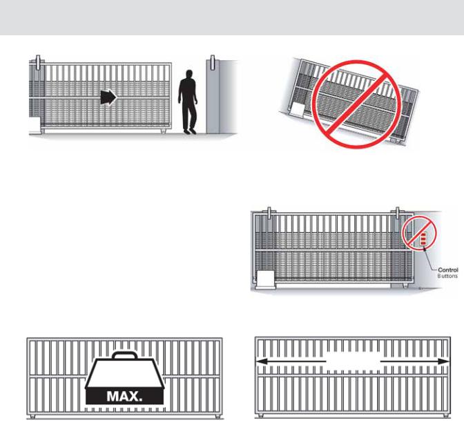
!WARNING: For use with gates at a maximum 7000 lbs. in weight or 120 ft. in length.
DO NOT allow pedestrian use of this gate |
DO NOT install the gate operator to lift gates |
Locate Control Buttons:
1.Within sight of the gate,
2.At a minimum height of 5 feet so small children are not able to reach it; and
3.At least 6 feet away from all moving parts of the gate.
120 ft
7000 lb.
Specifications |
|
Maximum Gate Length: |
120 ft. |
Maximum Gate Weight: |
7000 lb. |
Operating Temperature: |
-20°F (-28°C) to 160°F (71°C) |
Power Requirements: |
115 VAC / 230 VAC (8.0* amp / 4.0 amp) *Includes 3 amp load on receptacle |
|
Single Phase (50Hz / 60Hz) |
VIKING TECHNICAL SUPPORT 1.800.908.0884 |
13 |
|
|
 Loading...