

Page 1

INSTALLATION
INSTRUCTIONS
AND SAFETY INFORMATION
FOR THE VIKING K-2S GATE OPERATOR
NEW IMAGE
CLASS I
Solar Residential Vehicular
Slide Gate Operator
Page 2
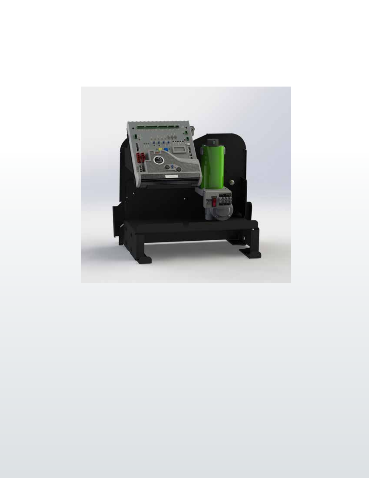
The K-2S™ Viking Solar Gate Operator has the capacity to operate
slide gates up to 700 lbs. and 30 ft. long under extreme conditions.
This efcient operator provides a solution for residential slide gate
solar applications thanks to its efcient electromechanical design.
Equipped with latest solar innovations, the K-2S™ is the most energy
efcient slide gate operator offered on the market.
THE VIKING K-2S™ SOLAR SLIDE GATE OPERATOR
Page 3

K-2s Solar Vehicular Gate Operator • Revision SK2MN10.F4 • April 2019
VIKING TECHNICAL SUPPORT 1.800.908.0884
1
Page 4
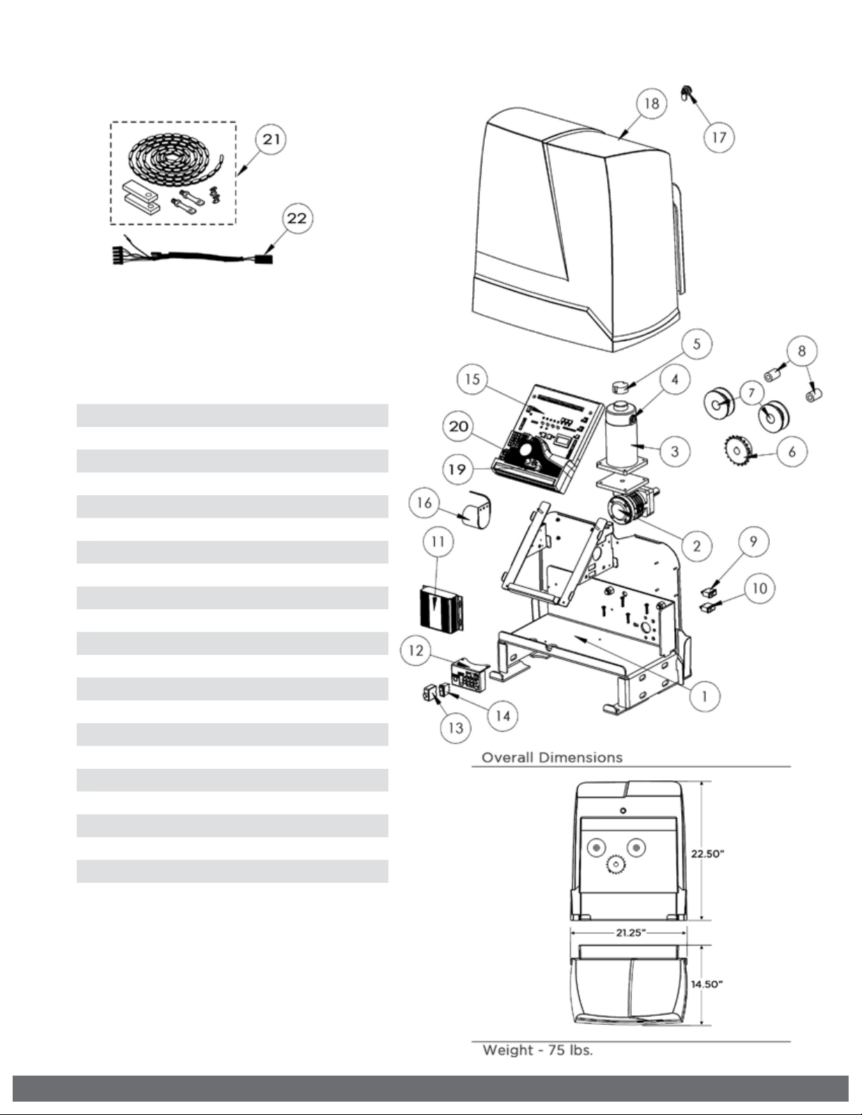
PARTS DIAGRAM:
Item Description Part No.
1 Chassis VSK2CH
2 Gearbox VNXK2GB
3 Motor VSK2MO
4 Brush Kit VAMBK
5 Electronic Positioning Sensor 2 (EPS2) VNXSLEPS2
6 Sprocket VAL3SP17
7 Idler Pulley DSIP10
8 Idler Bushing DSIB10
9 Manual Release Switch DUMRS10
10 Power Switch DUMRS10
11 Solar Charger VSCHARGSL
12 Solar Terminal Block Assembly VSTBASL
13 Solar Battery Breaker VASBB25
14 Solar Panel Switch DUMRS5
15 Solar Control Board VSPCBU18
16 Alarm DUAL10
17 Lock Cylinder & Key(s) VNXSLCL
18 Operator Cover VNXK2CV
19 Fuse - 4 amp VNXF4A
20 Fuse - 15 amp VNXF15A
21 25’ #40 Chain Kit, Nickel Coated VAL3CKN
22 Motor Harness VNXK2MH
2
VIKING TECHNICAL SUPPORT 1.800.908.0884
Page 5
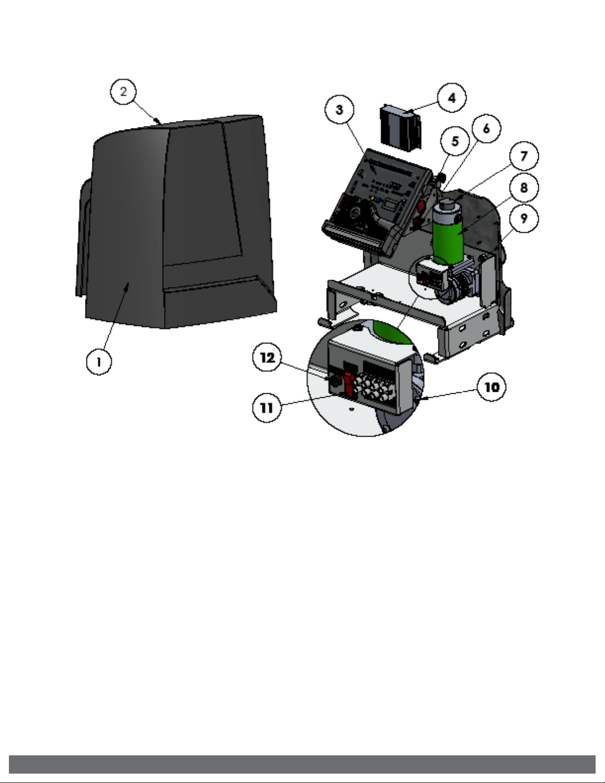
OPERATOR REFERENCES:
1.
OPERATOR COVER
2.
COVER LOCK
3.
SOLAR CONTROL BOARD
4.
SOLAR CHARGER
regulates and distributes solar power
5.
MANUAL RELEASE/MOTOR SWITCH
discontinues power to the motor and allows for
manual operation of the gate
6.
POWER SWITCH
discontinues all power to the control board
7.
EPS (ELECTRONIC POSITIONING SENSOR)
sensor for the digital limits
8.
MOTOR
9.
GEAR BOX
10.
SOLAR TERMINAL BLOCK ASSEMBLY
connections for solar panels and battery
11.
SOLAR PANEL SWITCH/BREAKER
discontinues power from the solar panels to the
Solar Charger
12.
BATTERY BREAKER
resettable breaker protects the battery circuit
VIKING TECHNICAL SUPPORT 1.800.908.0884
3
Page 6
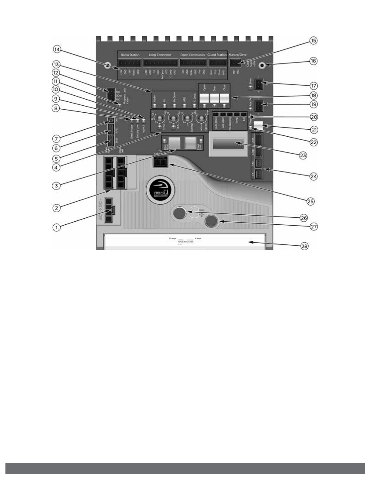
CONTROL BOARD REFERENCES:
1.
POWER HARNESS CONNECTOR
provides power to the control board.
pg 20
2.
“OPEN LEFT” & “OPEN RIGHT”
provides power to the motor. pg 21
3.
LIMIT SETUP BUTTONS
sets limit positions. pg 21-22
4.
FEATURE ACTIVATION TRIM POTS
activate and set features. pg 24
5.
“EPS1” CONNECTOR
communication for Viking Solar
Charger.
6.
“EPS2” CONNECTOR
monitors the limit positions.
7.
“EMI” CONNECTOR
not applicable to this model.
8.
“CHECK MOTOR” Status LED
indicates motor power status. pg 36
9.
“BATTERY LOW” Status LED
indicates battery power status. pg 36
10.
“POWER” Status LED
control board power status. pg 36
11.
“MAGNETIC LOCK RELAY” Status LED
status of this on-board relay. pg 36
12.
“MAGNETIC LOCK RELAY” Terminal Block
connect electric locks here. pg 36
13.
INPUT STATUS LEDs
indicates input status. pg 36-37
14.
ACCESS CONTROL TERMINAL BLOCKS
accessory connections. pg 29-32, 42-44
15.
“MASTER/SLAVE” Terminal Block
wired master/slave connection. pg 23
16.
CONTROL BOARD MOUNTING HOLES
secures and grounds the control board.
17.
“Siren” TERMINAL BLOCK
Vikings UL Siren is connected here.
18.
ON-BOARD 3 BUTTON STATION
controls the gate during set up.
19.
“AUX. PWR” Terminal Block
used for solar applications & in-motion
warning devices. pg 20, 25
20.
FEATURE ACTIVATION PIN HEADERS
activate features by placing a jumper
onto the pin headers. pg 25
21.
“DIAGNOSE” Button
allows you to navigate through the
Diagnostics LCD Display. pg 38-40
22.
“DIAGNOSE” LED
informs that errors have been detected
and available on LCD Display. pg 38-40
23.
LCD DIAGNOSTICS DISPLAY
provides error messages, diagnostics
and operator status information.
pg 38-40
24.
EXPANSION PRODUCT CONNECTIONS
connections for additional products
from Viking Access Systems. pg 46
25.
“FAIL SAFE/SECURE” Jumper
power failure option. pg 25
26.
FUSE HOLDER - 15 AMP
for motor circuit.
27.
FUSE HOLDER - 4 AMP
not applicable to this model.
28.
HEAT SINK
secures the control board and
dissipates heat.
4
VIKING TECHNICAL SUPPORT 1.800.908.0884
Page 7

TABLE OF CONTENTS:
2
OPERATOR REFERENCES
3
13
GATE OPERATOR INSTALLATION
14-17
23
CONTROL BOARD SETUP 24-26
ACCESSORY CONNECTIONS 28-35
TROUBLESHOOTING
36-41
VIKING EXPANSION PRODUCTS
46
APPENDIX A, B
42-44
CONTROL BOARD REFERENCES
4
6-12
PARTS DIAGRAM/PARTS LIST 2
OPERATOR REFERENCES 3
CONTROL BOARD REFERENCES 4
IMPORTANT SAFETY INFORMATION 6-12
Important Safety Instructions 6
Important Installation Instructions 7
Maintenance 8
General Safety Precautions 8-9
Operator Classification 9
Entrapment Protection Requirements 10
Entrapment Protection Installation 11
Manual Release 11
Audible Alarm Reset Installation 12
Warning Placard Installation 12
IMPORTANT INSTALLATION INFORMATION 13
Specifications 13
GATE OPERATOR INSTALLATION 14-17
Concrete Pad Option 14
Post Mounting Option 15
Operator Positioning 16-17
ELECTRICAL INSTALLATION 18-20
Battery & Solar Panel Selection 18
Solar Panel Care & Installation Tips 19
Solar Connection & Power Saving Tips 20
LIMITS SETUP 21-22
MASTER/SLAVE SET UP 23
CONTROL BOARD SETUP 24-26
Initial Settings 24-25
Obstruction Detection Sensor (ODS) 26
ACCESSORY CONNECTIONS 28-35
UL, Re-Open (Monitored Input Terminals) 28-29
Radio Receiver (Typical) 30
Anti-Tail Gate, Open Commands, Guard Station 31
Viking Loop Rack 32
Guidelines for Loop Installations 33
Blank Page 34
Barrier Arm Synchronization 35
TROUBLESHOOTING 36-41
LED References 36-37
LCD Display References 38-40
Solutions 41
APPENDIX A, B 42-44
VIKING EXPANSION PRODUCTS 46
VIKING TECHNICAL SUPPORT 1.800.908.0884
5
Page 8

IMPORTANT SAFETY INFORMATION
! WARNING! Not Following these instructions may cause severe injury or death.
IMPORTANT SAFETY INSTRUCTIONS
! WARNING! To reduce the risk of severe injury or death.
1.
READ AND FOLLOW ALL INSTRUCTIONS.
2.
Never let children operate or play with gate controls. Keep the remote away from
children.
3.
Always keep people and objects away from the gate. NO ONE SHOULD CROSS THE
PATH OF THE MOVING GATE.
4.
Test the gate operator monthly. The gate MUST reverse on contact with a rigid object or
when an object activates the non-contact sensors. After adjusting the force or the limit
travel, retest the gate operator. Failure to adjust and retest the gate operator properly
can increase the risk of injury or death.
5.
Use the emergency release only when the gate is not moving.
6.
KEEP GATES PROPERLY MAINTAINED. Read the user’s manual. Have a qualified service
person make repairs to gate hardware.
7.
The entrance is for vehicles only. Pedestrians must use a separate entrance.
8.
Every gate operator installation MUST have secondary protection devices against
entrapment, such as edge sensors and photo beams more in particularly in places
where the risk of entrapment is more likely to occur.
9.
SAVE THESE INSTRUCTIONS.
IMPORTANT INSTALLATION INSTRUCTIONS
1.
Install the gate operator only when:
a.
The operator is appropriate for the construction of the gate and usage Class of the
gate (refer to page 9),
b.
All openings of a horizontal slide gate are guarded or screened from the bottom of
the gate to a minimum of 6 feet (1.83 m) above the ground to prevent a 2-1/4 inch
(57.2 mm) diameter sphere from passing through the openings anywhere in the gate,
and in that portion of the adjacent fence that the gate covers in the open position,
c.
ALL EXPOSED PINCH POINTS ARE ELIMINATED OR GUARDED, AND
d.
GUARDING IS SUPPLIED FOR EXPOSED ROLLERS.
2.
The Operator is intended for installation only on gates used for vehicles. Pedestrians
must be supplied with a separate access opening. The pedestrian access opening
shall be designed to promote pedestrian usage. Locate the gate such that persons will
not come into contact with the vehicular gate during the entire path of travel of the
vehicular gate.
3.
The gate must be installed in a location so that enough clearance is supplied between
the gate and adjacent structures when opening and closing to reduce the risk of
entrapment. Swinging gates shall not open in to the public access areas.
4.
The gate must be properly installed and work freely in both directions prior to the
installation of the gate operator. Do not over-tighten the operator clutch or pressure
relief valve to compensate for a damaged gate.
5.
The gate operator controls must be placed so that the user has full view of the gate area
when the gate is moving AND AWAY FROM THE GATE PATH PERIMETER.
6.
Controls intended for user activation must be located at least six feet (6’) away from
any moving part of the gate and where the user is prevented from reaching over, under,
around or through the gate to operate the controls.
Exception: Emergency access controls only accessible by authorized personnel (i.e. fire,
police, EMS) may be placed at any location in the line-of-sight of the gate.
6
VIKING TECHNICAL SUPPORT 1.800.908.0884
Page 9

IMPORTANT SAFETY INFORMATION
! WARNING! Not Following these instructions may cause severe injury or death.
IMPORTANT INSTALLATION INSTRUCTIONS (Continued)
7. The Stop and/or Reset button must be located in the line-of-sight of the gate. Activation
of the reset control shall not cause the operator to start.
8. A minimum of two (2) WARNING SIGNS shall be installed, in the area of the gate. Each
placard is to be visible by persons located on the side of the gate on which the placard is
installed.
9. For gate operators using non-contact sensors (photoelectric beam or like) in
accordance with section 32.1.1 of the UL standard:
a. See instructions on the placement of non-contact sensors for each type of
application (refer to page 10).
b. Care shall be exercised to reduce the risk of nuisance tripping, such as when a
vehicle, trips the sensor while the gate is still moving, and
c. One or more non-contact sensors shall be located where the risk of entrapment or
obstruction exists, such as the perimeter reachable by a moving gate or barrier (refer
to page 10).
d. For UL compliance: Use only Omron: E3K-R10K4-NR-1 // EMX: IRB-RET, IRB-MON //
Miller Edge: RG-K-R, PG-K-R100, PG-K-R50, MIM-62
For ETL compliance: Use only Seco-Larm E-931-33PRGQ, E-936-S45RRGQ, E-931S50RRGQ, E-960-D90GQ // EMX NIR-50-325
10. For a gate operator utilizing a contact sensor (edge sensor or like) in accordance
with section 32.1.1 of the UL 325 standard:
a. One or more contact sensors shall be located where the risk of entrapment or
obstruction exists, such as a the leading edge, trailing edge, and post mounted both
inside and outside of a vehicular horizontal slide gate (refer to page 10).
b. One or more contact sensors shall be located at the bottom of a vehicular vertical lift
gate.
c. One or more contact sensors shall be located at the pinch point of a vehicular
vertical pivot gate.
d. A hardwired contact sensor shall be located and its wiring arranged so that
the communication between the sensor and the gate operator is not subject to
mechanical damage.
e. A wireless contact sensor such as one that transmits radio frequency (RF) signals
to the gate operator for entrapment protection functions shall be located where the
transmission of the signals are not obstructed or impeded by building structures,
natural landscaping or similar obstructions. A wireless contact sensor shall function
under the intended end-use conditions.
f. One or more contact sensors shall be located on the inside and outside leading edge
of a swing gate. Additionally, if the bottom edge of a swing gate is greater than 6
inches (152 mm) but less than 16 inches (406 mm) above the ground at any point in
its arc of travel, one or more contact sensors shall be located on the bottom edge.
g. One or more contact sensors shall be located at the bottom edge of a vertical barrier
(arm).
h. For UL compliance: Use only EMX: WEL-200K // Miller Edge: ME110 through ME117,
ME120, ME123, MG020, MGR20, MGS20, RB-G-K10, MIM-62 // ASO: 25.30, 25.45,
95.20
VIKING TECHNICAL SUPPORT 1.800.908.0884
7
Page 10

IMPORTANT SAFETY INFORMATION
! WARNING! Not Following these instructions may cause severe injury or death.
MAINTENANCE
Remove the Power Harness from the Control Board. (refer to page 20)
• Clean and lubricate the gate track wheels using the recommended lubricant.
•
Inspect the track for any signs of cracking or separation.
• Check that all mounting hardware of the gate operator is properly tighten.
• Ensure that the gate moves freely.
• Check for corroded parts and replace if necessary.
• Check the battery for the following:
- Battery connections must be free of corrosion.
- Battery voltage must be 13VDC (fully charged battery).
Reconnect the Power Harness for the Control Board. (refer to page 20)
• Check and confirm the proper operation of all safety devices (photoelectric
eye, edge sensors or like).
• Check and confirm the operation of all installed accessories.
• Check and confirm the operation of all special features such as the Intelligent
Obstruction Sensor, Hold Open Timer. (refer to page 24 and 26)
• Check and confirm the operation of the manual release. (refer to page 7)
GENERAL SAFETY PRECAUTIONS
The following precautions are an integral and essential part of the product and must be
supplied to the user. Read them carefully as they contain important indications for the
safe installation, use and maintenance.
• These instruction must be kept and forwarded to all possible future users of the
system.
• This product must be used only for that which it has been expressly designed.
• Any other use is to be considered improper and therefore dangerous.
• The manufacturer cannot be held responsible for possible damage caused by
improper, erroneous or unreasonable use.
• Avoid operating in the proximity of the hinges or moving mechanical parts.
• Do not enter the path of the moving gate while in motion.
• Do not obstruct the motion of the gate as this may cause a situation of danger.
• Do not allow children to play or stay within the path of the moving gate.
• Keep remote control or any other control devices out of the reach of children, in
order to avoid possible involuntary activation of the gate operator.
• In case of break down or malfunctioning of the product, disconnect from the main
power source. Do not attempt to repair or intervene directly, contact only qualified
personnel for repair.
• Failure to comply with the above may create a situation of danger.
• All cleaning, maintenance or repair work must be carried out by qualified personnel.
• In order to guarantee that the system works efficiently and correctly it is important
to have the manufacturer’s instructions on maintenance of the gate and operator
carried out by qualified personnel.
• In particular, regular checks are recommended in order to verify that the safety
devices are operating correctly.
All installation, maintenance and repair work must be documented and made
available to the user.
8
VIKING TECHNICAL SUPPORT 1.800.908.0884
Page 11
IMPORTANT SAFETY INFORMATION
! CAUTION: To Reduce the Risk of Fire or Injury to Persons:
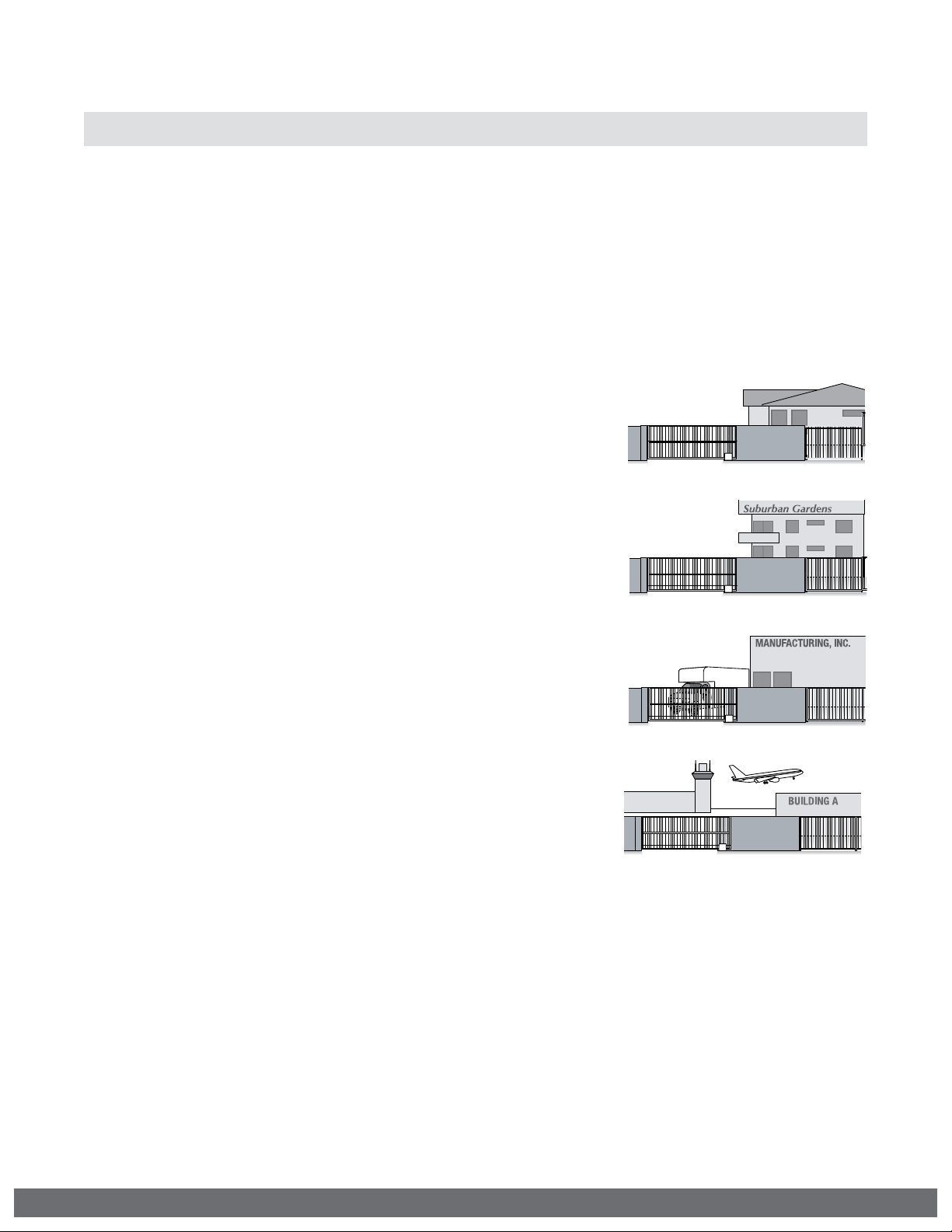
UL325 Gate Operator Classifications
GLOSSARY
RESIDENTIAL VEHICULAR GATE OPERATOR
CLASS I -
for use in garages or parking areas associated with a
residence of one-to four single families.
COMMERCIAL/GENERAL ACCESS VEHICULAR GATE OPERATOR
CLASS II –
intended for use in a commercial location or building
such as a multi-family housing unit (five or more single
family units), hotel, garages, retail store, or other
building servicing the general public.
A vehicular gate operator (or system) intended
A vehicular gate operator (or system)
INDUSTRIAL/LIMITED ACCESS VEHICULAR GATE OPERATOR
CLASS III –
intended for use in an industrial location or building
such as a factory or loading dock area or other
locations not accessible by or intended to service the
general public.
RESTRICTED ACCESS VEHICULAR GATE OPERATOR
CLASS IV –
intended for use in a guarded industrial location or
building such as an airport security area or other
restricted access locations not servicing the general
public, in which unauthorized access is prevented via
supervision by security personnel.
Install the gate operator only when:
The operator is appropriate for the construction of the gate and the Usage Class of
the gate.
A vehicular gate operator (or system)
A vehicular gate operator (or system)
VIKING TECHNICAL SUPPORT 1.800.908.0884
9
Page 12

IMPORTANT SAFETY INFORMATION
! WARNING! Not Following these instructions may cause severe injury or death.
Monitored Entrapment Protection Requirements
IMPORTANT: MONITORED PROTECTION MUST BE INSTALLED
•
REQUIRED BY UL 325, an approved MONITORED entrapment protection sensor is
REQUIRED to be installed in all areas accessible to potential entrapment and pinch
points.
•
For Slide Gate Operators, a minimum of two monitored entrapment sensors are required to
be connected as follows: Either one to the UL terminal and one connected to the Re-Open
terminal, OR two monitored devices connected to the UL terminal, one for EACH DIRECTION
of travel.
! An external sensor connected to the “Re-Open” input terminal will protect against
entrapment ONLY in the closing direction.
•
The installed sensor MUST be “10K Resistor Based”.
•
You may connect up to FOUR monitored sensors, wired in parallel, to either the “UL”
and/or “ReOpen” terminals, for a total of 8 monitored sensors.
•
Failure to install the required monitored entrapment protection sensor(s) may render
the gate operator INOPERABLE. The gate can be moved manually. Refer to page 11.
•
Consult the installation manual of the sensor for detailed information about the usage,
installation and maintenance.
•
Use only UL Recognized Component Edge Sensors and Photoelectric Sensors. Refer to
pg 7.
SLIDE GATE ENTRAPMENT ZONE – Locations between a moving gate and a counter opposing
edge or surface where entrapment is possible up to 1.8 m (6 ft) above grade. Such
locations occur if during any point in travel the gap between a moving gate and fixed
counter opposing edges or surfaces is less than 406 mm (16 in).
Photoelectric Sensor (non-contact sensor)
Edge Sensor (contact sensor)
10
VIKING TECHNICAL SUPPORT 1.800.908.0884
Page 13
IMPORTANT SAFETY INFORMATION
! WARNING! Not Following these instructions may cause severe injury or death.
! Cable use in Class 2 circuit to an external device shall be type CL2, CL2P, CL2R, CL2X or other
cable with equivalent or better electrical, mechanical, and fl ammability ratings.
Monitored Entrapment Protection Installation
! IMPORTANT: A minimum of two Monitored External Entrapment Sensors are required to be
connected as follows: One to the UL terminal and one connected to the Re-Open terminal,
OR two snesors connected to the UL terminal, one for EACH DIRECTION of travel.
“UL” Protects against entrapment in both the opening and closing directions. Input will
reverse the gate momentarily in the opposite direction it was traveling. Refer to page 28.
“Re-Open” Protects against entrapment in the closing direction ONLY. Input will reverse the
gate all the way to the Open Limit. Refer to page 29.
STEP 1:
sensor(s) to the Viking control board as illustrated.
Connect the monitored entrapment protection
10K Monitored Terminal
10K Monitored Terminal
UL LEARN
NO LEARN
UL SENSOR ERRORS:
If an problem occurs with one of the monitored
entrapment sensors, the “Stop” LED will flash and
an ERR message will be displayed, indicating which
input terminal(s) the sensor is connected to.
TERMINAL: “UL” “Re-Open” “UL” & “Re-Open”
ERROR
MESSAGE:
STEP 2:
Execute the Learn Process:
•
Toggle the “Diagnose” button
until you see UL LEARN NO LEARN
on the LCD Display.
•
Press and hold the “Stop” button.
•
Toggle the “Diagnose” button
once.
•
The number of Monitored sensors
connected to the “UL” or ReOpen terminals will now be
displayed.
EXAMPLE: UL LEARN
UL2 RO1
ERR SENSULERR SENSROERR SENS
UL RO
Manual Release
When manual operation is required:
1.
Remove the operator cover
2.
Press the Manual Release Switch
(top) to the “RELEASE” Position.
The gate can now be moved manually.
To resume normal operation, press
the switch to the “ENGAGE” position.
VIKING TECHNICAL SUPPORT 1.800.908.0884
MANUAL RELEASE
SWITCH
11
Page 14
IMPORTANT SAFETY INFORMATION
! WARNING! Not Following these instructions may cause severe injury or death.
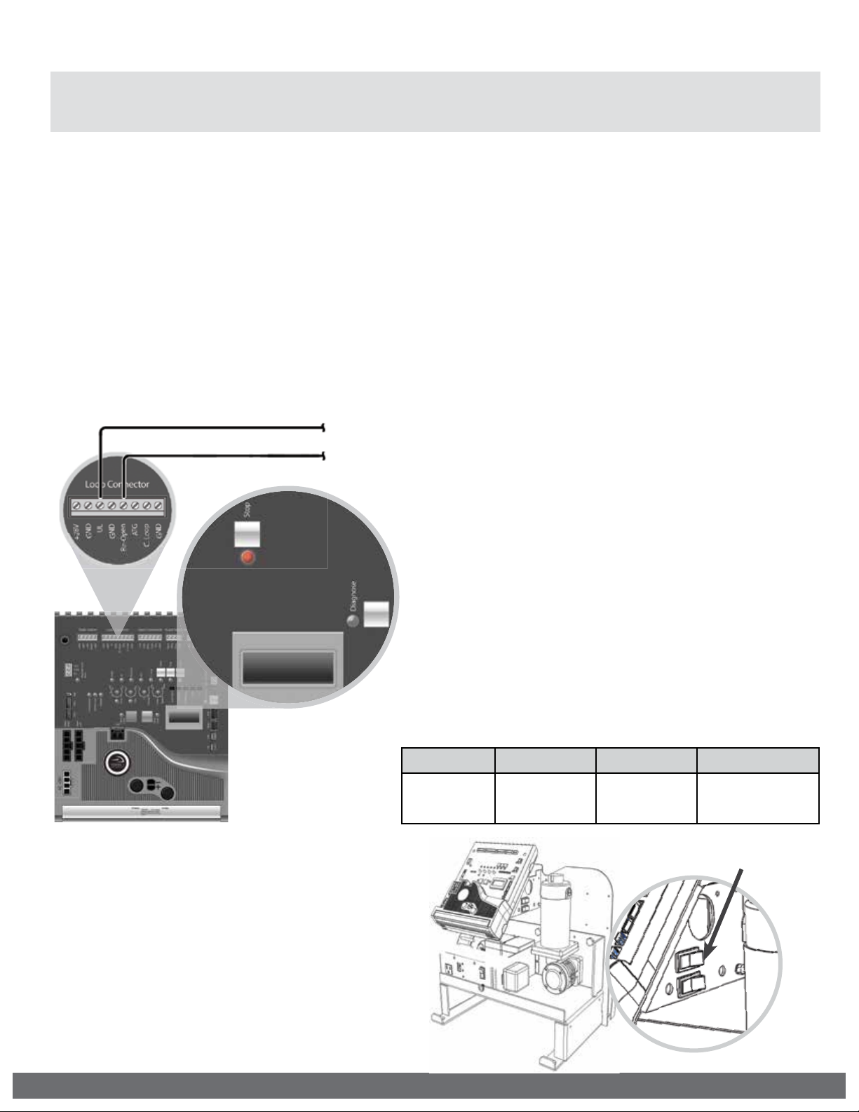
Audible Alarm Reset Switch Installation
Manual Reset for the Audible Alarm
•
UL325 standard requires an audible alarm to sound after two consecutive events
detected by the inherent entrapment protection of the gate operator (obstruction
sensor).
•
The audible alarm will continue to sound for 5 minutes or until a stop command
gets actuated.
•
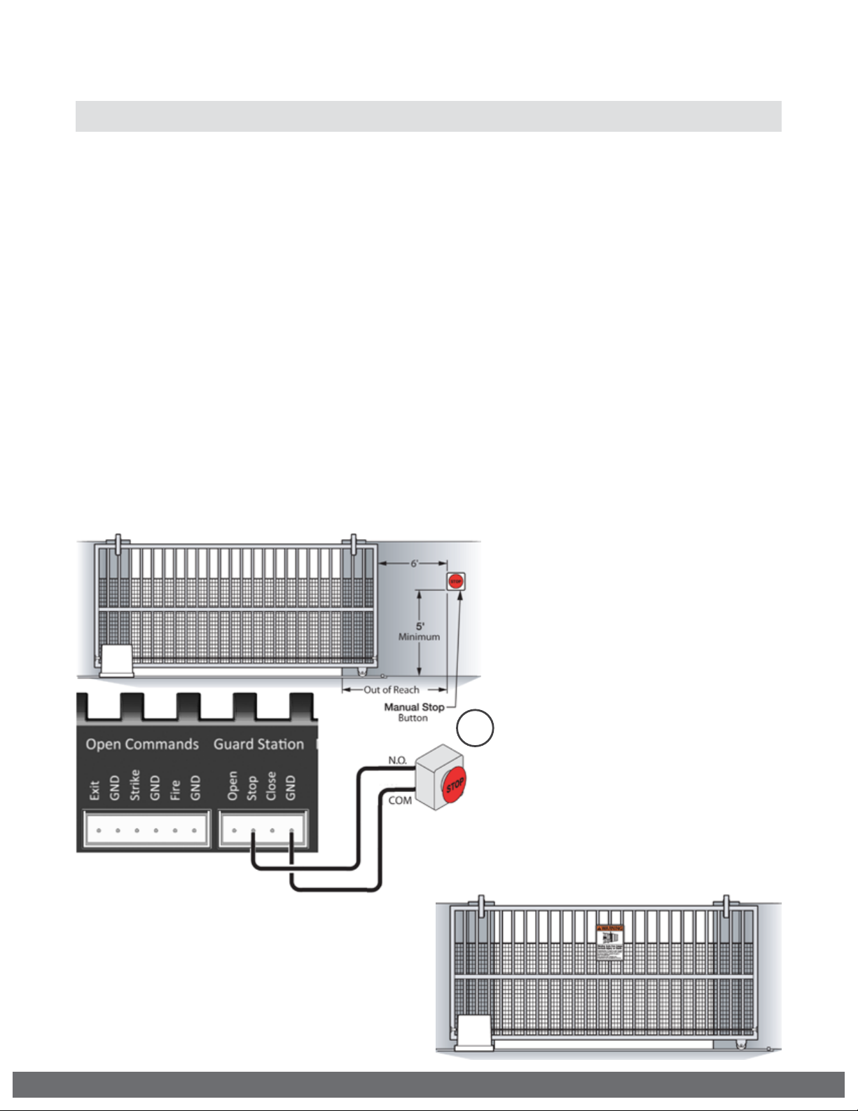
The Stop command can be actuated in two different forms:
1.
Using the Built in Stop switch on the Control Board or;
2.
Using an External Stop button within the sight of the gate, away from moving
parts of the gate and out of reach of children.
a.
Controls intended for user activation must be located at least six feet (6’)
away from any moving part of the gate and where the user is prevented from
reaching over, under, around or through the gate to operate the controls.
Outdoor or easily accessible controls shall have a security feature to prevent
unauthorized use.
b.
The Stop and/or Reset button must be located in the line-of-sight of the gate.
Activation of the reset control shall not cause the operator to start.
Warning Placard Installation
•
All Warning Placards must be installed
where visible in the area of the gate.
•
A minimum of two placards shall be installed.
•
A placard is to be installed in the area of
each side of the gate and be visible.
12
2
VIKING TECHNICAL SUPPORT 1.800.908.0884
Page 15

IMPORTANT INSTALLATION INFORMATION
! CAUTION: To Reduce the Risk of Fire or Injury to Persons:
! WARNING: For use with gates at a maximum 700 lbs. in weight or 30 ft. in length.
DO NOT allow pedestrian use of this gate DO NOT install the gate operator to lift gates
Locate Control Buttons:
1.
Within sight of the gate,
2.
At a minimum height of 5 feet
so small children are not able to
reach it; and
3.
At least 6 feet away from all
moving parts of the gate.
700 lb.
K-2S Specications:
UL 325 Classifcation: Class I
Maximum Gate Length: 30 ft.
Maximum Gate Weight: 700 lb.
Operating Temperature: -4°F (-20°C) to 160°F (71°C)
*Refer to page 9
30 ft
VIKING TECHNICAL SUPPORT 1.800.908.0884
13
Page 16

GATE OPERATOR INSTALLATION
Concrete Pad Option
1.
Follow the local building code to determine the required depth of the
concrete pad.
2.
Pad measurements recommended by Viking Access Systems are at least
24” long, 18” wide and 24” deep to ensure the stable operation of the
operator, and a minimum of 4” above level grade to avoid any flooding of
the machinery.
3.
Provide a sufficient number of conduit pathways for all low power
accessories such as loop detector leads, maglock, non-contact sensors,
contact sensors, safety and other commands. Also provide conduit for the
power supply to the operator.
! DO NOT run low voltage and high voltage wiring in the same conduit.
! Provide at least 12” separation between low and high voltage conduits.
14
VIKING TECHNICAL SUPPORT 1.800.908.0884
Page 17

GATE OPERATOR INSTALLATION
Post Mounting Option
TIP:
The operator is equipped for post mount applications and is ready for installation.
You will only need to supply the posts and U-Bolts.
1.
Consult the local building codes for the depth and concrete requirements.
2.
Maximum 3.00” OD pipe.
3.
Provide a sufficient number of conduit pathways for all low power accessories such as loop detector leads, maglock, non-contact sensors, contact
sensors, safety and other commands. Also provide conduit for the power
supply to the operator.
! DO NOT run low voltage and high voltage wiring in the same conduit.
! Provide at least 12” separation between low and high voltage conduits.
VIKING TECHNICAL SUPPORT 1.800.908.0884
15
Page 18

GATE OPERATOR INSTALLATION
Operator Positioning
! IMPO R TA NT: All openings of a horizontal slide gate are guarded or screened from the bot-
tom of the gate to a minimum of 6 feet (1.83 m) above the ground to prevent a 2-1/4 inch
(57.2 mm) diameter sphere from passing through the openings anywhere in the gate, and
in that portion of the adjacent fence that the gate covers in the open position.
16
VIKING TECHNICAL SUPPORT 1.800.908.0884
Page 19

GATE OPERATOR INSTALLATION
! TECHNICAL TIP: Before completing the installation procedure;
•
Open and close the gate manually, making sure there is suf cient space between the gate
and adjacent walls.
•
Check that the wheels are turning freely on the track and there are no restrictions while
pushing the gate to the open and closed positions.
•
Con rm that there is adequate spacing for the guide rollers and that there are no
restrictions throughout the travel of the gate.
STEP 1
Before securing the chassis to the concrete pad
or posts, make sure the gate and operator are
LEVEL and PARALLEL.
Minimum distance between the center of the
chain and the inside edge of the gate frame is 4”.
STEP 2
Chain Installation: Before welding the provided
chain brackets, make sure the chain will be in
a straight line with, and at the same height as,
the chain leaving the gate operator rollers.
STEP 3
Chain Tension: The chain tension has a direct
effect on the motor current draw, or work
that the motor is performing. Adjust the Chain
to provide 6” of slack measured from the
imaginary taut line, straight down to the lowest
point of the chain as illustrated below.
VIKING TECHNICAL SUPPORT 1.800.908.0884
17
Page 20

ELECTRICAL INSTALLATION
SAVE THESE INSTRUCTIONS - This manual contains important instructions for the
K-2s model gate operator that shall be followed during installation and maintenance
of the charge controller.
Battery Selection
•
Battery is sold separately.
•
Use only UL recognized 12V Sealed Lead Acid (SLA)
•
35Ah Maximum battery capacity.
Battery Care and Location
•
Use at least 12AWG wire, rated 90°C or better.
•
A 35Ah battery can be stored on the chassis of the
operator, below the control board.
•
Ensure the battery terminals will maintain a 1/4”
spacing from all other circuits and metal parts.
•
Do not dispose of the battery in re. The cells may explode.
Check with local codes for possible disposal instructions.
•
Do not open or mutilate the battery. Released electrolyte
is corrosive and may cause damage to the eyes or skin. It
may be toxic if swallowed.
•
Exercise care in handling batteries in order not to short the
battery with conducting materials such as rings, bracelets
and keys.
•
CAUTION - A battery can present a risk of electrical shock,
burn from high short circuit current, re or explosion from
vented gasses. Observe proper precautions.
•
Observe proper polarity orientation between the battery
and charging circuit.
Battery
Storage
Solar Panel Selection
•
Solar panel(s) are sold separately.
•
Use only UL Listed 12V solar panel(s), such as Viking part #s:
Wattage Viking Part#
20 Watts VA-SO20W 21.7V 1.25A
40 Watts VA-SO40W 21.8V 2.57A
Open-Circuit
Voltage
Short-Circuit
Current
Ratings
System Voltage: 12V
Max. Solar Wattage: 40W
Max. Solar Voltage: 29V
Max. Battery Capacity: 35Ah
Min. Battery Voltage: 8V
Max. Charger Load Current: 3A
Output Voltage for Controls: 24V This is the voltage the control board will provide
! Important: The number of cycles achieved daily is dependent on many factors,
including current draw of the motor and accessories, and local solar radiation data.
If more specific information is needed please consult with Viking Access Systems.
For more information regarding solar energy refer to: http://rredc.nrel.gov/solar/
pubs/redbook/
18
VIKING TECHNICAL SUPPORT 1.800.908.0884
Page 21

ELECTRICAL INSTALLATION
Solar Panel Care and Location
•
Where it will receive maximum sunlight throughout the year.
•
Avoid trees and buildings or obstructions, which could cast shadows on the panel.
•
South facing and tilted at an inclined angle that is equal to latitude.
•
If dirt build-up becomes excessive, clean the glass with a soft cloth using a mild
detergent and water.
•
Install solar panels in the following conditions:
•
Operating temperature: -40°F to 185°F
•
Humidity: Below 85RH%
•
Wind pressure: Below 50.12lb / ft² (2400Pa)
•
Snow load pressure: Below 112.76lb / ft² (5400 Pa)
•
DO NOT install the solar panel near open flames or flammable materials.
•
DO NOT install the solar panel where there is a risk of being immersed in water or
continually exposed to water from a sprinkle, fountain, etc..
Solar Panel Safety Precautions
! Installation must be performed by a qualified technician.
•
Before installing your system, contact local authorities and determine the
necessary permit, installation and inspection requirements.
•
Follow all local codes and guidelines.
•
To reduce the risk of electrical shock or burns, the solar panel must be covered
with an opaque material during installation.
•
Do not touch live terminals with bare hands as they can present a risk of electrical
shock, burn or fire.
Solar Panel Installation (per article 690 of ANSI/NFPA 70)
•
Use appropriate methods to mount the solar panel. Fall of the panel from high
places will cause death, injury or damage.
•
The solar panel must be mounted on a post with a supporting structure to support
wind and snow loads rated for use by the appropriate local or civil codes.
•
Use stainless steel washers between the panel and the supporting frame to prevent
electrolysis corrosion.
•
Use conduit and the appropriate wire type for outdoor applications.
•
Properly ground solar panel and operator according to NEC code.
•
Use the appropriate wire size according to distance and the maximum power
(Watt) rating of the solar panel, or panels combined.
•
Use at least 16 AWG photovoltaic cable or 90°C, sunlight and moisture resistant
direct burial cable or better.
•
WARNING - This charge controller must be used with an external GFDI device as
required by article 690 of the National Electric Code for the installation location.
Tips for proper ground installation:
•
Use a ground rod to provide a ground reference.
•
Consult your city code and be aware of under-ground
services in the site of the gate operator to prevent
inconveniences.
•
Always use a single bonding point for grounding.
•
All ground wires must be as short and as thick as
possible.
•
Prevent unnecessary turns or loops in all ground
wires.
VIKING TECHNICAL SUPPORT 1.800.908.0884
19
Page 22

Power Saving Tip:
The solar VFlex “control board” shuts
down the power at the“Aux. Pwr”
Terminal when the board is in sleep
mode.
To save energy, get the power for your
non-essential devices (such as photo
beams) from this terminal.
Er PANEL
LOW
ER PANEL
HIGH
ER SOLAR
NO PANEL
ERR NO
Sol UNIT
ERR CHRG
HIGH
ERR BAT
LOW
20
Indicates that the voltage being provided from the solar panel is too low.
Indicates that the voltage being provided from the solar panel is too High.
Indicates that there is no voltage being provided from the solar panel
Indicates that there is no voltage being provided from the solar panel.
Potential problem with the Solar Charger.
The battery is low
VIKING TECHNICAL SUPPORT 1.800.908.0884
Page 23

LIMITS SETUP
! IMPORTANT: In the event of a complete power failure, including battery backup, the
limits positions may have been cleared and will need to be reset by following the
steps below.
STEP 1
Connect the “Motor Harness” to the
Control Board.
a.
“OPEN RIGHT” Connector if the gate
opens to the Right, when viewed from
inside.
b.
“OPEN LEFT” Connector if the gate
opens to the Left, when viewed from
inside.
1a
1b
STEP 2
Move the gate to the desired open
position then press and hold the “Open
Limit” button until the LED stops flashing
and illuminates solid.
“Open Limit” LED
flashes if the open
limit is not set.
STEP 3
Move the gate to the desired close
position then press and hold the “Close
Limit” button until the LED stops flashing
and illuminates solid.
“Close Limit” LED
flashes if the close
limit is not set
Tip: The gate can be moved electronically with the “Open”, “Stop” and “Close” buttons
on the Control Board or manually by following the instructions on page 11.
VIKING TECHNICAL SUPPORT 1.800.908.0884
21
Page 24

LIMITS SETUP
! NOTE:
1.
The 1st cycle after the limit setup is the “Learn Cycle”. Allow a complete cycle to
confirm your settings.
2.
During the limit setup process, the operator will run at half speed.
Open
Limit
To Readjust the Open Limit:
1.
Clear the current limit setting by
holding down the “Open Limit” button
until the LED is flashing.
2.
Repeat STEP 2 on page 21 to set the
limit.
22
Close
Limit
To Readjust the Close Limit:
1.
Clear the current limit setting by
holding down the “Close Limit” button
until the LED is flashing.
2.
Repeat STEP 3 on page 21 to set the
limit.
VIKING TECHNICAL SUPPORT 1.800.908.0884
Page 25

MASTER/SLAVE SETUP
Step 2
At the Master Operator:
Connec
t the entrapment
Two Wire Communication
!
IMPORTANT: DO NOT run the Master/Slave communication cable in the same conduit
or within 12” of 115 - 230V power supply cables.
! Technical Tip: DO NOT set the “Timer” and/or “Overlap” features on both operators
Control Boards. Only turn these features on at the Master Control Board.
Step 1
Connect shielded cable to “Master/Slave” connectors at the control boards
CABLE REQUIREMENTS:
•
2 Conductor (wire)
•
18 AWG or better
•
Shielded (overall foil)
•
Drain Wire (bare wire)
Drain Wire
MS1
MS2
Conduit
Step 2
At the Master Operator:
Connect the entrapment
protection sensor(s) as
described on page 11.
Step 3
At the Slave Operator:
Turn ON the SLAVE MODE
Feature:
•
Toggle the “Diagnose”
button until you see SLAVE
MODE on the LCD Display.
•
Default setting is OFF.
•
Press and hold the “Stop”
button.
•
Toggle the “Diagnose”
button once.
•
The feature should now be
displayed as “ON”.
Shielded
MS1
MS2
Cable
SLAVE MODE
ON
VIKING TECHNICAL SUPPORT 1.800.908.0884
23
Page 26

CONTROL BOARD SETUP
Initial Settings
“Timer”
Hold Open Timer
Automatically closes the gate after
the selected amount of time from 1-60
seconds.
Turning the dial between “0” and “OFF”
will disable this feature, requiring a close
command to close the gate.
“Overlap”
Overlap Delay
Delays the gate from opening for the
selected amount of time from 1-6
seconds.
! Typically not used on slide gates. For
Master/Slave application, the control
board that has this feature turned on
is the master and will close first.
“ODS”
Obstruction Detection Sensor
Sets the amount of force required to trip
the inherent obstruction sensor.
See page 26 for more details about this
feature.
24
“Speed”
Motor Speed
Increases or decreases the speed of gate
travel.
VIKING TECHNICAL SUPPORT 1.800.908.0884
Page 27

Initial Settings
CONTROL BOARD SETUP
NOTE:
Installing a shunt, or jumper, on the pins will activate the feature.
“Fail Safe/Secure”
During complete power
failure, including battery
power; determines the force
required to manually move
the gate.
•
Fail Safe Mode:
By removing the wirejumper plug from the “Fail
Safe/Secure” connector:
The gate can move
manually with a relatively
low amount of force.
•
Fail Secure Mode:
By inserting the wirejumper plug into the “Fail
Safe/Secure” connector:
The gate will not move
manually.
“Last Open” - Power Failure Option
Opens the gate automatically when the
battery backup voltage is critically low.
“Pre-Warning” Initiates two options for
an audio or visual warning, 3 seconds
prior to gate motion, and will continue:
1.
Until gate reaches closed limit:
“Magnetic Lock” terminals provide a
contact between “COM” and “N.O.”.
2.
Until gate reaches either limit:
“AUX. PWR” terminals provide 24VDC.
“Sync” Used only in conjunction with
the Viking Barrier gate operator model
B-12. Activating this feature allows for
synchronized operation with the B-12
operator. See page 35.
“EXT” Available for future developments.
! IMPORTANT: Regardless of the power failure options chosen, the gate can be moved
manually with a relatively low amount of force by following the steps for “Manual
Release” as outlined at on page 11.
VIKING TECHNICAL SUPPORT 1.800.908.0884
25
Page 28

CONTROL BOARD SETUP
Obstruction Detection Sensor (ODS)
!
IMPORTANT: The appropriate “ODS” setting is dependant upon the gate installation
and construction. Set this feature accordingly. Additional Safety equipment should
be used to reduce possible risk of injury or vehicle damage.
“ODS” Obstruction Detection Sensor
The Obstruction Sensor detects
obstructions in the path of the traveling
gate. The dial sets the amount of force
required to activate the operators inherent
obstruction detection.
Setting the dial to “0” will require the least
amount of force to activate;
Setting the dial to “100” will require the
maximum amount of force to activate.
UL325 standard requires an audio
alarm to go off after two consecutive
entrapment events sensed by the
Inherent Entrapment Protection of the
Gate Operator.
The audio alarm will sound for a period
of 5 minutes or until a Stop command
or the “Alarm Reset” switch has been
actuated. (refer to page 12)
When the Obstruction Sensor detects
an obstruction it will:
1.
Stop the gate’s movement and reverse
it momentarily.
2.
Bring the gate to a resting position.
3.
Disable the Hold Open Timer feature
until the Gate Operator receives a new
command.
If second obstruction is detected before
the gate reaches either limit it will:
1.
Stop the gate’s movement.
2.
Disable the Gate Operator.
3.
Sound the UL Alarm
4.
A STOP command must be provided
to disable the alarm and continue
operation.
! TECHNICAL TIP: The Status LED for the
“ODS” will indicate the following
when it has been triggered.
A.
Solid: Obstruction.
Detected a sudden or abrupt increase
in gate resistance.
B.
Flashing: Overload.
Detected a more subtle, but sustained
increase in gate resistance.
26
VIKING TECHNICAL SUPPORT 1.800.908.0884
Page 29

(THIS PAGE LEFT BLANK INTENTIONALLY)
VIKING TECHNICAL SUPPORT 1.800.908.0884
27
Page 30

ACCESSORY CONNECTIONS
! Cable use in Class 2 circuit to an external device shall be type CL2, CL2P, CL2R, CL2X or
other cable with equivalent or better electrical, mechanical, and fl ammability ratings.
UL (Monitored Input Terminal)
The “UL” input terminal protects against entrapment in both the opening and closing
directions. Input will reverse the gate momentarily in the opposite direction it was
traveling when a connected device it triggered. see pages 10-11.
Check for proper operation:
•
When a connected device
is triggered, the “UL” LED
will illuminate to indicate an
input. The “Stop” LED will also
illuminate if there is more than
one Monitored device connected.
•
It is important to note that if
more than one Monitored device
is connected to this terminal, the
“UL” LED will be illuminated. This
alone is inconsequential.
•
The “Stop” LED will flash if there
is a failure with at least one
Monitored entrapment sensor
and the gate operator will be
rendered inoperable.
! TECHNICAL TIP: For more information
regarding accessory connections
to the control board and individual
input terminal functions, refer to
“Appendix (A)” pages 42-43.
28
VIKING TECHNICAL SUPPORT 1.800.908.0884
Page 31

ACCESSORY CONNECTIONS
! Cable use in Class 2 circuit to an external device shall be type CL2, CL2P, CL2R, CL2X or
other cable with equivalent or better electrical, mechanical, and fl ammability ratings.
Re-Open (Monitored Input Terminal)
The “Re-Open” input terminal protects against entrapment in the closing direction
ONLY. Input will reverse the gate all the way to the Open Limit when a connected
device it triggered. see pages 10-11.
Check for proper operation:
•
When a connected device is
triggered, the “Re-Open” LED
will illuminate to indicate an
input. The “Stop” LED will also
illuminate if there is more than
one Monitored device connected.
•
It is important to note that
if more than one Monitored
device is connected to this
terminal, the “Re-Open” LED
will be illuminated. This alone is
inconsequential.
•
The “Stop” LED will flash if there
is a failure with at least one
Monitored entrapment sensor
and the gate operator will be
rendered inoperable.
! TECHNICAL TIP: For more information
regarding accessory connections
to the control board and individual
input terminal functions, refer to
“Appendix (A)” pages 42-43.
VIKING TECHNICAL SUPPORT 1.800.908.0884
29
Page 32

ACCESSORY CONNECTIONS
COM
N.O.
(-)
(+)
! Cable use in Class 2 circuit to an external device shall be type CL2, CL2P, CL2R, CL2X or
other cable with equivalent or better electrical, mechanical, and fl ammability ratings.
Radio Receiver (Typical)
!
IMPORTANT: The Hold Open “Timer” setting (page 24) affects how the gate will
respond to the radio receiver command.
The control board provides two modes
of operation that a radio receiver can
control the gate:
Open-Stop-Close
1.
By having the radio receiver connected
as illustrated and with the Hold Open
Timer OFF (see page 24):
Every command of the radio transmitter
will control the gate as follows:
a.
First command opens the gate,
b.
Second command stops the gate and
c.
Third command closes the gate
d.
Any subsequent commands will
continue in the same order to control
the gate.
This type of configuration is not
recommended for commercial
installations.
! TECHNICAL TIP: For more information
regarding accessory connections
and terminal functions, refer to
“Appendix (A)” on pages 42-43.
See “Appendix (B)” on page 44 for
connecting common radio receiver
models.
30
Open Only
2.
By having the radio receiver connected
as illustrated and with the Hold Open
Timer ON (see page 24):
Each command of the radio transmitter is
ALWAYS AN OPEN COMMAND to the gate.
For maximum reception range:
Locate the radio antenna to
the top of the gate column.
VIKING TECHNICAL SUPPORT 1.800.908.0884
Page 33

ACCESSORY CONNECTIONS
! Cable use in Class 2 circuit to an external device shall be type CL2, CL2P, CL2R, CL2X or
other cable with equivalent or better electrical, mechanical, and fl ammability ratings.
Anti-Tailgate, Open Commands & Guard Station
!
TECHNICAL TIP: For more information regarding accessory connections and terminal
functions, refer to “Appendix (A)” on pages 42-43.
Open Commands
“Exit”, “Fire” and “Strike” input terminals
all provide an open command to the
control board. Any device connected as
shown will open the gate.
-
+ +
N.O.
-
COM
N.O.
COM
-
+
“ATG” Anti-Tailgate
This input will stop the
gate when the vehicle
triggers the sensor, then
closes the gate when the
vehicle leaves the sensor,
preventing unauthorized
vehicles from entry.
N.O.
COM
Guard Station
All three buttons must be a
!
Normally Open “N.O.” type of
switch, and can share the same
common “C” connection to “GND”.
-
+
VIKING TECHNICAL SUPPORT 1.800.908.0884
COM
N.O.
31
Page 34

ACCESSORY CONNECTIONS
Viking Loop Rack
TIP:
This operator may be equipped with a pre-wired Loop Rack that plug-in type loop
detectors can be connected to. This provides a convenient alternative to the box
type loop detectors that would need to be wired to the control board. Viking does
not provide either type of loop detectors.
Loop Rack: Part # VA-LR
Loop Rack Wiring Harness: Part # VA-LRH
32
VIKING TECHNICAL SUPPORT 1.800.908.0884
Page 35

ACCESSORY CONNECTIONS
Guidelines for Loop Installation
1.
Prevent sharp corners in the geometry of the loop sensor.
2.
Install the appropriate number of turns for your loop geometry based on the loop
perimeter. Use Table C (below) as a guide.
3.
Use XLP (cross-linked-polyethylene) type of wire. This wire reduces the effects
of moisture and other environmental events in altering the functionality of the
vehicular loop detector.
4.
Twist the lead wire at least 6 turns per foot.
5.
Use BACKER-ROD to minimize damage to the loop detector wire prior to using the
sealant.
6.
Place the loop detector wire and adjust the sensitivity of the vehicular loop
detector unit in a way to minimize the effects of the gate over the loop detector
wire.
! IMPORTANT! Some of the following parameters may affect the proper
functionality of the vehicular loop detector.
Consult the manufacturer of the vehicular loop detector and/or loop wire.
• Gate size
• Number of turns in the loop sensor wire
• Distance of the loop sensor wire to the gate at either at the open or close position
Table C - Recommended Number of Turns
Perimeter (ft.) Number of Turns
10 5
20 4
30-40 3
50-100 2
Dimension “A” - 5’ for Single Gate
6’ for Dual Gate
VIKING TECHNICAL SUPPORT 1.800.908.0884
33
Page 36

(THIS PAGE LEFT BLANK INTENTIONALLY)
34
VIKING TECHNICAL SUPPORT 1.800.908.0884
Page 37

ACCESSORY CONNECTIONS
Barrier Arm Synchronization
NOTE:
synchronized operation with the Barrier Arm Operator.
This type of application opens and closes in the following pattern:
1.
2.
3.
STEP 1 (Figure A)
At the Barrier Arm operator, connect the
device(s) that will be used as the primary
OPEN input.
The Control Board provides a convenient solution for applications that require
Open Command is provided only to the Barrier Arm operator.
The Barrier Arm will send an open input to the Viking gate operator; Barrier Arm will
delay to open until the Viking gate operator reaches its Open Limit.
Barrier Arm will close first; the Viking gate operator will delay to close until the Barrier
Arm reaches its Close Limit.
STEP 2 (Figure A & B)
Connect the Barrier Arms’ designated
sync output terminals to the Strike input
at the Viking gate operator.
1
2
STEP 3
At the Viking gate operator, activate
Sync Mode by placing a jumper on to the
pin headers labeled “SYNC”.
3
4
STEP 4
Connect Magnetic Lock relay terminals
(“COM” and “N.C.“) to the Barrier Arms’
designated sync input terminals.
VIKING TECHNICAL SUPPORT 1.800.908.0884
35
Page 38

TROUBLESHOOTING
LED References
In addition to the LCD Display, the control board LEDs monitor the various circuits of the
control board. Use the table below to identify the corresponding “TS Ref#” and refer to
page 38-41 for further troubleshooting.
# LED Status Meaning
1 “Magnetic
Lock Relay”
2 “Check Motor” OFF Normal Condition.
3 “Battery Low” OFF Normal Condition.
4 “POWER” OFF No power to control board (pg 20) or board is in sleep mode.
5 “Radio” OFF Normal Condition.
6 “UL” OFF Normal Condition.
7 “Re-Open” OFF Normal Condition.
8 “ATG” OFF Normal Condition.
OFF At Closed Limit and Magnetic Lock Relay state is closed across “COM” &
“N.C.”. Gate should be at the Close Limit.
SOLID Not at Closed Limit and Magnetic Lock Relay state is closed across “COM” &
“N.O.”. Gate should not be at the Close Limit
SOLID The control board is sending power to the motor but the circuit is open.
SOLID Does not apply to Solar Units.
FLASHING Batteries critically low. Check power supply to the operator (pg 20).
SOLID Normal Condition.
SOLID Control Board is receiving an input from a device connected to the
Radio terminal (pg 30, 42).
SOLID Control Board is receiving an input from a device connected to the UL
terminal or when more than one device is connected (pg 10-11, 28, 42).
SOLID Control Board is receiving an input from a device connected to the Re-
Open terminal or when more than one device is connected (pg 10-11, 29,
32, 42).
SOLID Control Board is receiving an input from a device connected to the ATG
terminal (pg 31, 42).
Page 41
TS Ref#(s)
7, 8
5
9, 10
9, 10, 16,
22
9, 10, 16,
22
9, 10
36
VIKING TECHNICAL SUPPORT 1.800.908.0884
Page 39

TROUBLESHOOTING
LED References
Use the table below to identify the corresponding “TS Ref#” and refer to page 38-41 for
further troubleshooting.
Pg 41
# LED Status Meaning
9 “C Loop” OFF Normal Condition.
SOLID Control Board is receiving an input from a device connected to the
10 “Open” OFF Normal Condition.
SOLID Control board is receiving an input from a device connected to any of
11 “STOP” OFF Normal Condition.
SOLID Control Board is receiving an input from a device connected to the
FLASHING There is a problem with the required monitored sensor(s) connected
12 “Close” OFF Normal Condition.
SOLID Control Board is receiving an input from a device connected to the
13 “Siren”
14 “Aux. Pwr”
15 “Diagnose” OFF Normal Condition.
“Close Limit”
16
17
“Open Limit”
18 “ODS” OFF Normal Condition.
19 “Timer” OFF The close timer is turned OFF or gate is not at the open limit if the timer is
OFF Normal Condition.
SOLID Second consecutive obstruction has been detected. (pg 24, 26).
FLASHING Batteries are critically low.
OFF No voltage output on these terminals at the moment.
SOLID There is 24VDC output on these terminals at the moment.
FLASHING Errors have been detected; Check LCD Display for ERR messages (pg 40).
OFF Gate is not at the close limit position.
SOLID Gate is at the close limit position.
FLASHING Close limit position has been erased or not set (pg 21-22).
OFF Gate is not at the open limit position.
SOLID Gate is at the open limit position.
FLASHING Open limit position has been erased or not set (pg 21-22).
SOLID Obstruction has been detected. (pg 26).
FLASHING Overload has been detected. (pg 26).
SOLID Gate is at Open Limit, Timer is turned ON and counting down to close. (pg
FLASHING Gate is at Open Limit, Timer is turned ON but is not timing out due to a
C Loop terminal (pg 32, 42).
the following input terminals: Exit, Fire, Strike or Open (pg 31, 42).
Stop, UL or Re-Open terminals (pg 12, 31, 42).
to the “UL” and/or “Re-Open” input terminals (pg 10-11, 23 and 28-29) 16, 22
Close terminal (pg 31, 42).
turned ON. (pg 24).
24).
conicting command. (pg 24). 9, 10
TS Ref#(s)
9, 10
9, 10
9, 10
9, 10
11, 13
6
6
11, 13
11, 13
VIKING TECHNICAL SUPPORT 1.800.908.0884
37
Page 40

TROUBLESHOOTING
LCD Display References
The control board is equipped with a LCD Display that provides operator information,
current conditions, settings, diagnostics and error messages. Use the table below to
identify the corresponding “TS Ref#” and refer to page 41 for further troubleshooting.
1.
Error Messages will be displayed rst.
2.
The ”Diagnose” LED will ash consecutively
indicating how many Error Messages are
available.
3.
Press the Diagnose button to manually
scroll through all of the Messages.
Page 41
LCD MSG Meaning
TS Ref #s
MODEL
K2S
GATE IS
IDLE
GATE IS
OPENING
GATE IS
CLOSING
GATE IS
OPENED
GATE IS
CLOSED
STOP BY
OBSTRUCT
STOP BY
OVERLOAD
Indicates the Model of the unit
System Status Messages
Gate is stopped between limits
Gate is opening
Gate is closing
Gate is at the limit open position
Gate is at the limit close position
Gate stopped due to an obstruction sensor event
Gate stopped due to an overload of the gate system
11, 12,
13
11, 12
OVERLAP
TIMING
HOLDING
__ SEC
EPS2
OK
UL LEARN
UL_ RO_
38
Gate is waiting for the overlap time
Gate is at the limit open position and timing to close - The display shows
the actual time left before closing
While the gate is running, indicates the percentage of accuracy of the EPS.
“OK” indicates 100% accurate communication
Indicates the number of connected Monitored Entrapment Protection
Sensors that are being monitored. NO LEARN = no sensors learned. (pg 11)
VIKING TECHNICAL SUPPORT 1.800.908.0884
Page 41

LCD Display References
LCD MSG Meaning
Multi Meter Displays
TROUBLESHOOTING
Page 41
TS Ref #s
MOT AMP
__._ A
MOT VOLT
__._ VDC
SOL VOLT
__._ VAC
CHARGE
__._ VDC
BAT VOLT
__._ VDC
EPS2
___% ERR
Speed
__%
OVERLAP
_._ SEC
This is the motor current amperage during operation.
This is the actual motor voltage during operation.
This is the actual voltage from the solar panel.
Indicates the voltage being supplied to the Control Board from the Viking
Solar Charger.
This is the actual voltage from the Battery
Board Settings Messages
Indicates that the Electronic Positioning Sensor (EPS) needs to be tuned.
Error rate is displayed as a percentage
Shows the percentage of speed set by the Speed adjustment on the control
board. (pg 24)
Shows the number of seconds set by the Overlap Adjustment on the
control board. This feature is not available on slide gate operator models
ODS SENS
Shows the force setting selected to trip the obstruction sensor. (pg 26)
___%
TIMER
__ SEC
VIKING TECHNICAL SUPPORT 1.800.908.0884
Shows the amount time set or remaining to hold the gate at the Open Limit
position, before the gate starts to close. (pg 24)
39
Page 42

TROUBLESHOOTING
LCD Display References
LCD MSG Meaning
Error Messages
ERR EPS2
WRONG
The EPS (Electronic Positioning Sensor) has one of the following
conditions: a) The EPS is not properly adjusted b) The EPS has a potential
connection problem c) The EPS has the wrong cable harness
Page 41
TS Ref #s
?
ERR EPS2
MISSING
ERR ___
LIMIT
ERR FUSE
15 AMP
Er PANEL
LOW
ER PANEL
HIGH
ER SOLAR
NO PANEL
ERR NO
Sol UNIT
ERR CHRG
HIGH
Missing or damaged EPS2 cable harness
Indicates that the open “OPN”, close “CLS“ or both “NO“ limits are cleared
and need to be set.
15 Amp motor fuse is blown
Indicates that the voltage being provided from the solar panel is too low.
Indicates that the voltage being provided from the solar panel is too High.
Indicates that there is no voltage being provided from the solar panel
Indicates that there is no voltage being provided from the solar panel.
Potential problem with the Solar Charger.
14, 17
6
7, 11, 12
?
?
?
?
?
ERR BAT
LOW
ERR SENS
UL RO
40
The battery is low
There is a problem with the required monitored sensor(s) connected
to the “UL” and/or “Re-Open” input terminals (pg 10-11, 23, 28-29).
VIKING TECHNICAL SUPPORT 1.800.908.0884
?
22
Page 43

TROUBLESHOOTING
Solutions
Begin the troubleshooting process by referring to the error messages on the LCD
Display and/or the Status LEDs on the control board. Use pages 36-40 to identify
the Troubleshooting Reference # (TS Ref#) then reference the table below.
TS Ref# CHECK Page Ref#
1 Not applicable to this model.
2 Not applicable to this model.
3 Not applicable to this model.
4 Not applicable to this model.
5 Check that the Power Harness is connected to the control board.
Set the limit position.
6
7 Check the Motor Fuse on the control board. pg 4
8 Check that the “Manual Release” switch is turned to the “Engage” position. pg 3, 11
9
Check the Status LEDs and LCD Display to determine if the control board is
receiving an input from any external devices or if the “ODS” has been triggered.
Remove the external devices from the control board to determine if the control
10
board is responding to an input or problem with the external device or wiring.
11
Check the gate, track and chain for any debris or cause for resistance. Check
the “ODS” setting on the control board.
12
Check that the gate can be moved manually with low resistance throughout its
full length of travel.
Check the limit position.
13
14
Check the cable for the Electronic Positioning Sensor for damage. Clean the
connection pins.
15
Not applicable to this model.
Check the LCD Display for Error Messages.
16
17
Check that the cable from the Electronic Positioning Sensor is connected to the
“EPS2” port on the Control Board.
18 Not applicable to this model.
Manually adjust any setting on the Control Board to clear all wireless override
19
settings.
20 Not applicable to this model.
21 Not applicable to this model.
22
Check the required entrapment protection sensors.
Call Viking Technical Support for further assistance.
?
pg 4, 20
pg 21-22
pg 24, 26,
36-38
pg 29-32,
36-37
pg 8, 12,
26
pg 8, 17
pg 21-22
pg 4
pg 40
pg 3-4
pg 10-11,
23, 28-29
VIKING TECHNICAL SUPPORT 1.800.908.0884
41
Page 44

Appendix (A)
“N.O.”
“N.O.”
Anti -Tailgat e
“N.O.”
Access Control Connections
Power Connections
The control board provides a 24VDC output to power external devices and controls.
Alternatively, for devices that require a power supply other than 24VDC, the
operators Power Box contains a convenient 120VAC receptacle to connect a plug-in
transformer.
“C” = Common
Terminals Connections and Input Functions:
“N.O.” = Normally Open
Viking Terminal Function Device Terminal
“+28V” --------------------- DC Positive --------------- “+”
“GND” --------------------- DC Negative --------------- “–”
“GND” --------------------- Relay Common --------------- “C”
“Radio” “N.O.”
If “Timer” OFF: Open - Stop - Close
If “Timer” ON: Open / Reopen if closing
“U L” (see pages 10-11 & 28) “N.O.”
If stopped: Prevents the gate from moving
If traveling: Stops then reverses gate momentarily
“Re-Open” (see pages 10-11 & 29) “N.O.”
If stopped: No function
If closing: Stops then Opens gate
“ATG ” A n ti-Tailgate “N.O.”
Input is received: Stops gate if closing
Input is released: Closes gate to prevent tailgating
“C. Loop” “N.O.”
If not at open limit: No function
If at open limit: Prevents gate from Closing
“Open”, “Exit”, “Fire” & “Strike” “N.O.”
If stopped: Opens gate
If closing: Stops then Opens gate
“Stop” “N.O.”
If traveling: Stops gate
“Close” “N.O.”
If stopped: Closes gate
If traveling: No function
! TECHNICAL TIP: Each input Terminal (i.e. Radio, Exit, Re-Open, UL) has a corresponding
Status LED that when illuminated indicates an input is currently being provided to the
terminal and the gate is responding accordingly. (See pages 36-37 LED References)
42
VIKING TECHNICAL SUPPORT 1.800.908.0884
Page 45

Relays In General
EXIT
+28V
GND
GND
APPENDIX (A)
NOTE:
controls. These items can be purchases from your dealer or distributor.
In General
In regards to the Viking control board,
all external safety devices and access
controls contain, and are, simple relays
that provide an input to the Viking
control board when the device is
activated.
When these devices are activated,
their internal relays create a contact,
or short, between the “C” and “N.O.”
terminals. This contact is what provides
the command to the Viking control
board.
! TECHNICAL TIP: Viking uses the
Normally Open “N.O.” contact from the
device, excluding “fail-safe” type photo
beams. In such instances, the Normally
Closed “N.C.” will be used instead.
Viking Access Systems does not provide the external safety devices and access
Glossary of Terms
1.
Terminal: Wire Connections.
2.
Input Terminal: On the Viking
control board, the terminal which is
labeled for a specific command (ReOpen, Exit, Radio, etc.). The N.O.
contact from the access control
device is to be connected to the Input
Terminal.
3.
Terminal Block: On the Viking
control board, a removable block
containing multiple terminals.
4.
Relay: The component of an access
control or safety device that provides
an input or command to the Viking
control board.
5.
“C” Relay Common Terminal: This is
the relay terminal that makes contact
(a short) to the N.O. terminal when the
device is activated. Always wire this
relay terminal to any “GND” terminal at
the control board.
6.
“N.O.” Relay Normally Open
Terminal: The relay terminal that has
an open contact to “C” while the relay
is not activated, and a closed contact
+
—
COM N.O.
N.C.
Not
Used
when the relay is activated. Almost
always wire this relay terminal to an
“Input Terminal” at the control board,
7.
“N.C.” Relay Normally Closed
Terminal: The relay terminal that has
a closed contact to “C” while the relay
is not activated, and an open contact
when the relay is activated. This
terminal is rarely used.
8.
Relay Coil: Contains the terminals
that provide power at the relay.
9.
“+” Relay Positive Terminal: Th e
positive power pole for the relay coil.
Always wire this relay terminal to any
“+28V” terminal at the control board.
10.
“–” Relay Negative Terminal: Th e
negative power pole for the relay coil.
Always wire this relay terminal to any
“GND” terminal at the control board.
VIKING TECHNICAL SUPPORT 1.800.908.0884
43
Page 46

Appendix (B)
! Cable use in Class 2 circuit to an external device shall be type CL2, CL2P, CL2R, CL2X or
other cable with equivalent or better electrical, mechanical, and fl ammability ratings.
Common Radio Receivers - Connections
44
VIKING TECHNICAL SUPPORT 1.800.908.0884
Page 47

(THIS PAGE LEFT BLANK INTENTIONALLY)
VIKING TECHNICAL SUPPORT 1.800.908.0884
45
Page 48

VIKING EXPANSION PRODUCTS
VIKING SOLAR Related Components:
12V 40W Solar Panels Part# VA-SO40W
12V 35Ah batteries Part# DUBA35
! NOTE: The number of cycles achieved are dependent upon the
following and may require increased panel and battery capacities:
•
Power consumption of all accessories being used
•
Average solar radiation of geographic location
46
VIKING TECHNICAL SUPPORT 1.800.908.0884
Page 49

OUR CONTINUOUS COMMITMENT TO EXCELLENCE
Viking Access Systems is continuously working hard to identify and
design products that will appeal to the industry and its needs. As
technology continues to advance, we have developed a completely
efcient and intelligent line of gate operators to meet the changing
demands. These machines offer: full UL325 and UL991 compliance,
soft-start and soft-stop, intelligent obstruction sensors, continuous
operation (100% duty cycle) and extreme power efciency. Innovative
features include: adaptive and self-learning algorithms, redundancy
design in both hardware and software to ensure operation and
functionality, protection from lightning, short circuit and power surges,
and our exclusive drive-train design offering the highest efciency
rating in the industry. Our entire product line is continually modied
and improved based on the latest technology and our customer’s
valuable feedback. The results are products that offer accuracy,
efciency, reliability and performance, all in sleek, high-tech designs.
We pledge to continue establishing ourself as the leader in high quality,
innovative gate operators by developing “Next Level” technology. We
are committed to providing safety and convenience with innovative
solutions for every security gate need.
Page 50

STANDARD FEATURES
• Single 12V battery and single 12V solar panel
operation.
• Most Advanced Charging System in the
industry.
• Power Saving Technology minimizes current
draw.
• Viking Solar Power Management System
maximizes the number of cycles per day
• Sleep Mode for non-essential accessories
minimizes current draw on stand-by.
• High Ef ciency Electro-Mechanical Design
increases the number of cycles per day.
• Twice, or more, the number of cycles per
day, with a 10W solar panel, compared to
other manufacturers.
• Real Time Status Display of the solar panel
voltage, charging voltage and battery
voltage.
• 5 years limited warranty (Visit our website
for more details).
• Built-in protection against lightning strikes
or similar electrical surges
• Inherent Overload Protection; Redundancy
Design with multiple types of protection.
• Zinc Plated and Powder Coated steel chassis.
• Easy access to manual operation, allowing
the gate to be move by hand, independently
of the operator.
• Fast and easy installation process.
• Convenient Digital Limit set up.
• Modular connectors for easy access control
and accessory installation.
• LCD display for monitoring and diagnostic
purposes.
• Self Diagnose Features conveniently displays
any errors in the system.
• Made in USA.
INSTALLATION DATE: __________________________________
COMPANY / INSTALLER: ________________________________
CO N TACT: __________________________________________
SERIAL NUMBER(S): ____________________________________
ALL INSTALLATION, MAINTENANCE AND REPAIR WORK MUST BE
DOCUMENTED AND MADE AVAILABLE TO THE USER.
VIKING ACCESS SYSTEMS
631 Wald Irvine, CA 92618
Phone 800.908.0884
Fax 949.753.1640
www.vikingaccess.com
 Loading...