

Page 1
INSTALLATION
INSTRUCTIONS
AND SAFETY INFORMATION
FOR THE VIKING G-5 GATE OPERATOR
CLASS I, CLASS II, CLASS III,
AND CLASS IV
Residential and Commercial
Vehicular Swing Gate Operator
VIKING BLUE ENABLED
SOLAR EFFICIENT OPERATION
Page 2
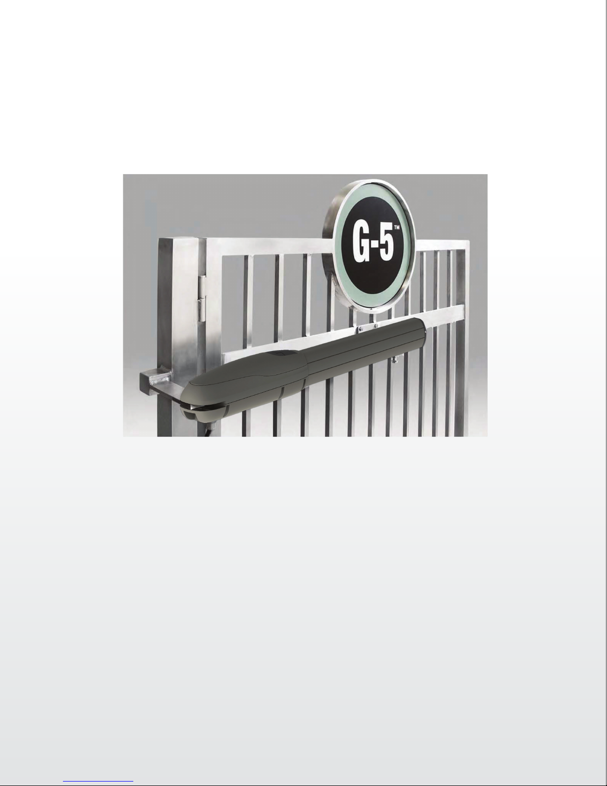
With its compact, low prole design and the power to support up
to 2000 lbs of weight or gate lengths of up to 18 feet, the Viking
G-5™ will revolutionize the idea of gate operation. This operator is
manufactured with the highest quality components and is designed
to accent any gate style. The G-5™ is capable of continuous cycles
operation at 24V DC, converted directly from an AC line. The battery
back-up provides up to 400 cycles of operation with a maximum
capacity gate.
THE VIKING G-5™ SWING GATE OPERATION
Page 3

G-5 Vehicular Gate Operator • Revision G5MN20.A • July 2012
Page 4

Page 5

TABLE OF CONTENTSTABLE OF CONTENTS
Parts Diagram/Parts List . . . . . . . . . . . . . . . . . . . . . . . . . . . . . . . . . . . . . . . . . . .i
Important Safety Information
Important Safety Instructions . . . . . . . . . . . . . . . . . . . . . . . . . . . . . . . . . . . . . .2
Important Installation Instructions . . . . . . . . . . . . . . . . . . . . . . . . . . . . . . . . .2-3
Maintenance/General Safety Precautions . . . . . . . . . . . . . . . . . . . . . . . . . . . . . .4
Terminology . . . . . . . . . . . . . . . . . . . . . . . . . . . . . . . . . . . . . . . . . . . . . . . . . .5
Photo Beam (non-contact sensor) Installation . . . . . . . . . . . . . . . . . . . . . . . . . .6
Edge Sensor (contact sensor) Installation . . . . . . . . . . . . . . . . . . . . . . . . . . . . . .7
Manual Release . . . . . . . . . . . . . . . . . . . . . . . . . . . . . . . . . . . . . . . . . . . . . . . .7
Audible Alarm Reset Switch Installation . . . . . . . . . . . . . . . . . . . . . . . . . . . . . .8
Warning Placard Installation . . . . . . . . . . . . . . . . . . . . . . . . . . . . . . . . . . . . . .8
Important Installation Information . . . . . . . . . . . . . . . . . . . . . . . . . . . . . . . . . .9
Specifications . . . . . . . . . . . . . . . . . . . . . . . . . . . . . . . . . . . . . . . . . . . . . . . . .9
of Installation – Open Inside . . . . . . . . . . . . . . . . . . . . . . . . . . . . . . . . . . .10
Plan
Plan of
Gate Operator Installation
Control Box Installation . . . . . . . . . . . . . . . . . . . . . . . . . . . . . . . . . . . . . . . . . . .16
Electrical Installation
ehicular Loop Detector Installation
V
ccessory Connections
A
Special Features
Optional Solar Panel Installation . . . . . . . . . . . . . . . . . . . . . . . . . . . . . . . . . .30-31
Pipe Stand Mount Kit . . . . . . . . . . . . . . . . . . . . . . . . . . . . . . . . . . . . . . . . . . .32-33
Optional VikingBlue Installation . . . . . . . . . . . . . . . . . . . . . . . . . . . . . . . . . . . . .34
Troubleshooting . . . . . . . . . . . . . . . . . . . . . . . . . . . . . . . . . . . . . . . . . . . . . . . .35-37
Installation – Open Outside . . . . . . . . . . . . . . . . . . . . . . . . . . . . . . . . . .11
Step 1 through 5 – Operator Installation . . . . . . . . . . . . . . . . . . . . . . . . . . . .12-13
Step 6 through 8 – Limit Switch and Positive Stop Setup . . . . . . . . . . . . . . . . .14
Opening/Closing Setup . . . . . . . . . . . . . . . . . . . . . . . . . . . . . . . . . . . . . . . . . .15
Reference Wiring Diagram; Limit Switch Connections . . . . . . . . . . . . . . . . . . . .15
Electrical Installation (120/220 VAC) . . . . . . . . . . . . . . . . . . . . . . . . . . . . . . . .17
Single Unit Connections . . . . . . . . . . . . . . . . . . . . . . . . . . . . . . . . . . . . . . . . .18
Master/Slave Connections . . . . . . . . . . . . . . . . . . . . . . . . . . . . . . . . . . . . . . . .19
Loop Layout Diagrams . . . . . . . . . . . . . . . . . . . . . . . . . . . . . . . . . . . . . . . . . .20
Installation Guidelines . . . . . . . . . . . . . . . . . . . . . . . . . . . . . . . . . . . . . . . . . . .21
Open Commands; Safety Connections . . . . . . . . . . . . . . . . . . . . . . . . . . . . . . . .22
Radio Receiver . . . . . . . . . . . . . . . . . . . . . . . . . . . . . . . . . . . . . . . . . . . . . . . .23
Viking Electromagnetic Lock . . . . . . . . . . . . . . . . . . . . . . . . . . . . . . . . . . . . . .24
Magnetic Lock; Solenoid; Guard Station . . . . . . . . . . . . . . . . . . . . . . . . . . . . . .25
Intelligent Obstruction Sensor (Primary Entrapment Protection) . . . . . . . . . . . . .26
Fail Safe/Fail Secure Operation; Hold Open Timer . . . . . . . . . . . . . . . . . . . . . . .27
Gate Overlap Setting . . . . . . . . . . . . . . . . . . . . . . . . . . . . . . . . . . . . . . . . . . . .28
Auto_open
Feature . . . . . . . . . . . . . . . . . . . . . . . . . . . . . . . . . . . . . . . . . . . . .29
TECHNICAL SUPPORT 1 800 908 0884
1
Page 6

IMPORTANT SAFETY INFORMATIONIMPORTANT SAFETY INFORMATION
WARNING - Not following these instructions may cause severe injury or death to persons.
IMPORTANT SAFETY INSTRUCTIONS
WARNING – To reduce the risk of severe injury or death:
1. READ AND FOLLOW ALL INSTRUCTIONS.
2. Never let children operate or play with gate controls. Keep the remote control away from children.
3.
Always keep people and objects away from the gate. NO ONE SHOULD CROSS THE PATH OF
THE MOVING GATE.
4. Test th
an object activates the non-contact sensors. After adjusting the force or the limit of travel,
retest the gate operator
risk of injury or death.
5. Use the manual release only when the gate is not moving.
6. KEEP GATES PROPERLY MAINTAINED. Read the owner’s manual. Have a qualified service pro-
fessional make repairs to gate hardware.
7. The entrance is for vehicles only.
8. Every gate operator installation
against entrapment, such as edge sensors and photo beams more in particularly
in places wher
9. SAVE THESE INSTRUCTIONS.
e gate operator monthly. The gate MUST reverse on contact with a rigid object or when
. Failure to adjust and retest the gate operator properly can increase the
Pedestrians must use a separate entrance.
T
MMUUSST
e the risk of entrapment is more likely to occur.
have secondary protection devices
IMPORTANT INSTALLATION INSTRUCTIONS
1. Install the gate operator only when:
a) The operator is appropriate for the construction of the gate and the usage Class of the gate
(refer to page 5),
b) All openings of a horizontal slide gate are guarded or screened from the bottom of the gate
to a minimum of 4 feet (1.22 m) above the ground to prevent a 2-1/4 inch (57.2 mm)
diameter sphere from passing through the openings anywhere in the gate, and in that
portion of the adjacent fence that the gate covers in the open position,
c) ALL EXPOSED PINCH POINTS ARE ELIMINATED OR GUARDED, AND
d) GUARDING IS SUPPLIED FOR EXPOSED ROLLERS.
2. The operator is intended for installation only on gates used for vehicles. Pedestrians must be
supplied with a separate access opening. The pedestrian access opening shall be designed to
promote pedestrian usage. Locate the gate such that persons will not come in contact with the
vehicular gate during the entire path of travel of the vehicular gate.
3.
The gate must be installed in a location so that enough clearance is supplied between the gate
and adjacent structures when opening and closing to reduce the risk of entrapment. Swinging
gates shall not open into public access areas.
4. The gate must be properly installed and work freely in both directions prior to the installation
of the gate operator. Do not over-tighten the operator clutch or pressure
relief valve to compensate for a damaged gate.
5. The gate operator controls must be placed so that the user has full view
of the gate area when the gate is moving AND AWAY FROM THE GATE
PATH PERIMETER,
2
TECHNICAL SUPPORT 1 800 908 0884
Page 7

IMPORTANT SAFETY INFORMATIONIMPORTANT SAFETY INFORMATION
WARNING - Not following these instructions may cause severe injury or death to persons.
IMPORTANT INSTALLATION INSTRUCTIONS Continued
6. Controls intended for user activation must be located at least six feet (6’) away from any moving part of the gate and where the user is prevented from reaching over, under, around or
through the gate to operate the controls. Outdoor or easily accessible controls shall have a security feature to prevent unauthorized use.
7. The Stop and/or Reset button must be located in the line-of-sight of the gate. Activation of the
reset control shall not cause the operator to start.
8. All warning signs and placards must be installed where visible in the area of the gate. A minimum
of two placards shall be installed. A placard is to be installed in the area of each side of the
gate and be visible to persons located on the side of the gate on which the placard is installed.
9. For gate operators utilizing a non-contact sensor (Photo beam or like) in
a
ccordanc
a) See instructions on the placement of non-contact sensors for each Type of
application (r
b) Care shall be exercised to reduce the risk of nuisance tripping, such as when
a vehicle, trips the sensor while the gate is still moving, and
c) One or more non-contact sensors shall be located where the risk of entrapment
or obstruction exists, such as the perimeter r
barrier (refer to page 6).
d) Use only Omr
e with section 31.1.1 of the UL325 standard:
efer to page 6),
eachable by a moving gate or
on E3K-R10K4 photoelectric eye to comply with UL325
10.
For a gate operator utilizing a contact sensor (Edge sensor or like) in
accordance with section 31.1.1 of the UL325 standard:
a) One or more contact sensors shall be located where the risk of entrapment or
obstruction exists, such as at the leading edge, trailing edge, and post mounted
both inside and outside of a vehicular horizontal slide gate (refer to page 7).
b) One or more contact sensors shall be located at the bottom edge of a vehicular
vertical lift gate.
c) One or more contact sensors shall be located at the pinch point of a vehicular
vertical pivot gate.
d) A hardwired contact sensor shall be located and its wiring arranged so that the
communication between the sensor and the gate operator is not subjected to
mechanical damage.
e) A wireless contact sensor such as one that transmits radio frequency (RF)
signals to the gate operator for entrapment protection functions shall be
located wher
by building structures, natural landscaping or similar obstruction. A wireless
contact sensor shall function under the intended end-use conditions.
f) One or more contact sensors shall be located on the inside and outside leading
edge of a swing gate. Additionally
than 6 inches (152 mm) above the ground at any point in its arc of travel, one
or mor
e contact sensors shall be located on the bottom edge (refer to page 7).
e the transmission of the signals are not obstructed or impeded
, if the bottom edge of a swing gate is greater
g) One or more contact sensors shall be located at the bottom
edge of a vertical barrier (arm).
h) Use only Miller Edge Model MGR20 or MGS20 edge sensor
to comply with UL325
TECHNICAL SUPPORT 1 800 908 0884
3
Page 8

IMPORTANT SAFETY INFORMATIONIMPORTANT SAFETY INFORMATION
WARNING - Not following these instructions may cause severe injury or death to persons.
MAINTENANCE
Remove the Power Harness from the Control Board (refer to page 17)
• Clean and lubricate the turning pins and gate hinges using the recommended lubricant.
• Clean and lubricate the lead screw using silicon grease.
• Check to ensure all mounting hardware of the gate operator is properly tightened.
• Ensure that the gate moves freely.
• Check for corroded parts and replace if necessary.
• Check
Reconnect the Power Harness to the Control Board (refer to page 17)
• Check and confirm the proper operation of all safety devices (photoelectric eye, edge sensors, ect.).
• Check and confirm the operation of all installed accessories.
• Check and confirm the operation of all special features such as the Intelligent Obstruction Sensor and
• Check and confirm the operation of the manual release (refer to page 7)
• Verify battery backup functionally by turning off the power source (120 VAC and 220 VAC).
the battery for the following:
Battery connections must be free of corrosion.
Battery voltage must be 26 VDC (fully charged battery).
Hold Open Timer (refer to page 20 to 27)
DO NOT FORGET TO TURN ON THE POWER SOURCE AFTER VERIFICATION.
GENERAL SAFETY PRECAUTIONS
The following precautions are an integral part of the product and must be supplied to the user.
Read carefully as they contain important Recommendations for the safe installation, use, and maintenance.
• These instruction must be kept and forwarded to all possible future users of the system.
• This product must be used only for that which it has been expressly designed.
• Any other use is to be considered improper and therefore dangerous.
• The manufacturer cannot be held responsible for possible damage caused by improper, erroneous, or
unreasonable use.
• Avoid operating in the proximity of the hinges or moving mechanical parts.
• Do not enter the path of the moving gate while in motion.
• Do not obstruct the motion of the gate as this may cause a situation of danger.
• Do not allow children to play or stay within the the path of the moving gate.
• Keep remote control or any other control devices out of the reach of children to avoid possible
involuntary activation of the gate operator.
• In case of break down or malfunction of the product, disconnect from the main power source. Do not
attempt to repair or intervene directly, contact only qualified
• Failure to comply with the above may create a situation of danger.
• All cleaning, maintenance, or repair work must be carried out by qualified personnel.
• In order to guarantee that the system works efficiently and correctly, it is important to have the manufacturer’s
instructions on maintenance of the gate and operator carried out by qualified personnel.
• In particular, regular checks are recommended in order to verify that the safety devices are operating correctly.
All installation, maintenance, and repair work must be documented and made available to the user.
personnel for repair.
Installer:
_____________________________________________________ ____________
Signature Date
Contact: _________________________________________________________
_________________________________________________________
4
TECHNICAL SUPPORT 1 800 908 0884
Page 9
IMPORTANT SAFETY INFORMATIONIMPORTANT SAFETY INFORMATION
CAUTION: To Reduce the Risk of Fire or Injury to Persons
a) Use only the following type and size of battery(ies): Yuasa NP7-12
b) Do not dispose of the battery(ies) in fire. The cells may explode. Check with local codes for possible dis-
posal instructions.
c) Do not open or mutalate the battery(ies). Released electrolyte is corrosive and may cause damage to the
eyes or skin. It may be toxic if swallowed.
d) Exercise care in handling batteries in order not to short the battery with conductive materials such as
rings, bracelets, and keys.
e) Change the battery(ies) provided with or identified for use with this product only in accordance with the
instructions and limitations specified in this manual.
f) Observe proper polarity orientation between the battery(ies) and charging circuit.
g) Do not mix batteries of different sizes or from different manufacturers in this product (applies to products
employing more than one user replaceable secondary battery).
h) A battery-operated product employing a secondary battery supply intended to be charged within the
product shall contain specific instructions concerning the proper method of charging.
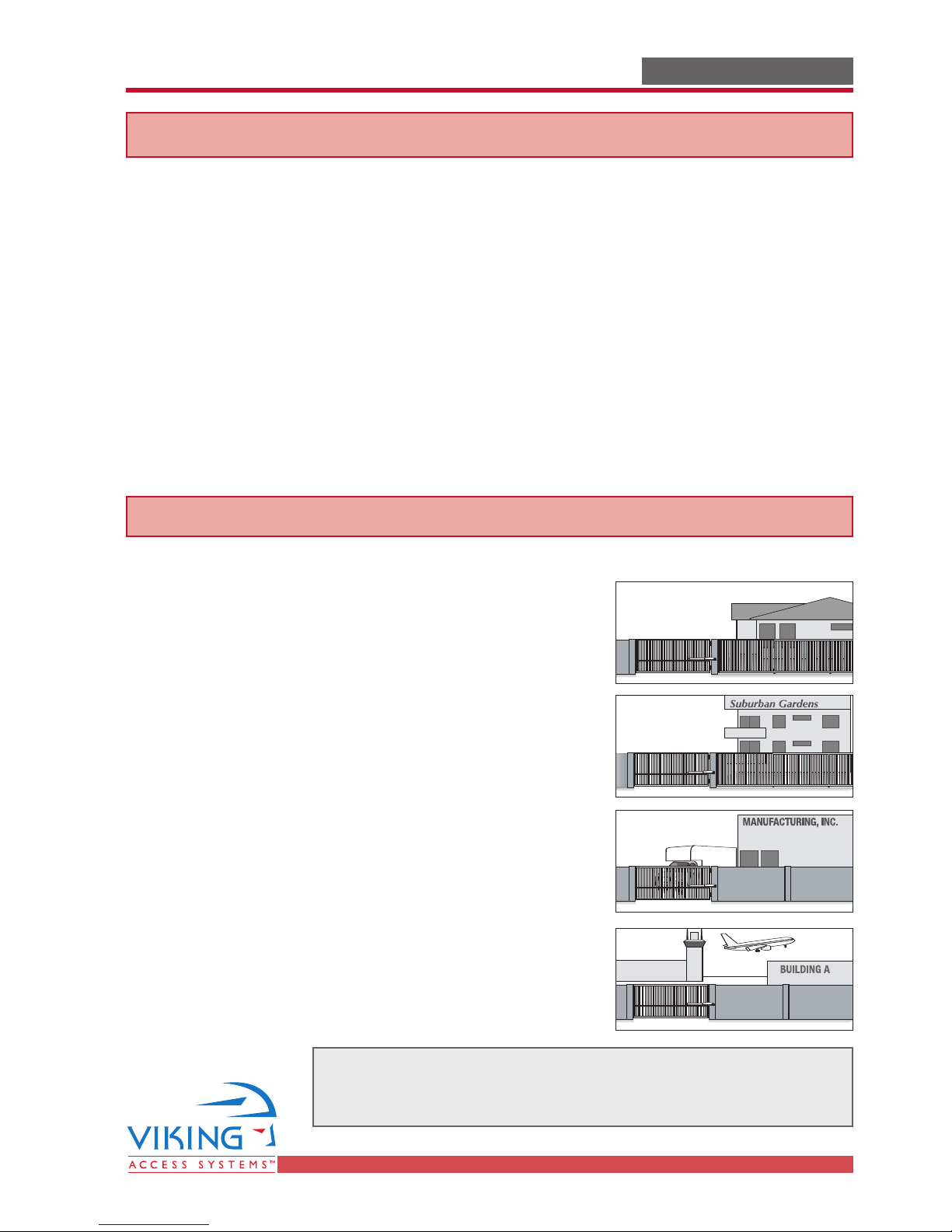
UL325 Gate Operator Classification
GLOSSARY
RESIDENTIAL VEHICULAR GATE OPERATOR
CLASS I – A vehicular gate operator (or system) intended for use
in a home of one-to four single family dwelling, or a garage or
parking area associated therewith.
COMMERCIAL/GENERAL ACCESS VEHICULAR GATE OPERATOR
CLASS II – A vehicular gate operator (or system) intended for use
in a commercial location or building such as a multi-family housing unit (five or more single family units), hotel, garages, retail
store, or other building servicing the general public.
INDUSTRIAL/LIMITED ACCESS VEHICULAR GATE OPERATOR
CLASS III – A vehicular gate operator (or system) intended for
use in an industrial location or building such as a factory or
loading dock area or other locations not intended to service the
general public.
RESTRICTED ACCESS VEHICULAR GATE OPERATOR
CLASS IV – A vehicular gate operator (or system) intended for
use in a guarded industrial location or building such as an airport security area or other restricted access locations not servicing the general public, in which unauthorized access is prevented
via supervision by security personnel.
TECHNICAL SUPPORT 1 800 908 0884
Install the gate operator only when:
The operator is appropriate for the construction of the gate
and the Usage Class of the gate.
55
Page 10

IMPORTANT SAFETY INFORMATIONIMPORTANT SAFETY INFORMATION
Radio Station
Lock
Mag. Lock
Rec.SensorLoopLoop
Charger
Power
Low Battery
Motor Sensor
Radio Station
Gnd
Radio
Gnd
+28v
+28v
Lock
MAG. LOCK
N.C.
COM
N.O.
Charger
Power
Low Battery
Check Motor
30
Off
1
Rec.
Sens
Loop
Loop
WARNING - Not following these instructions may cause severe injury or death to persons.
NOTE - This type of installation DOES NOT reverse the gate all the way back to its limits when the photo-beam
is obstructed. This installation is only to protect against entrapment and to comply with UL325.
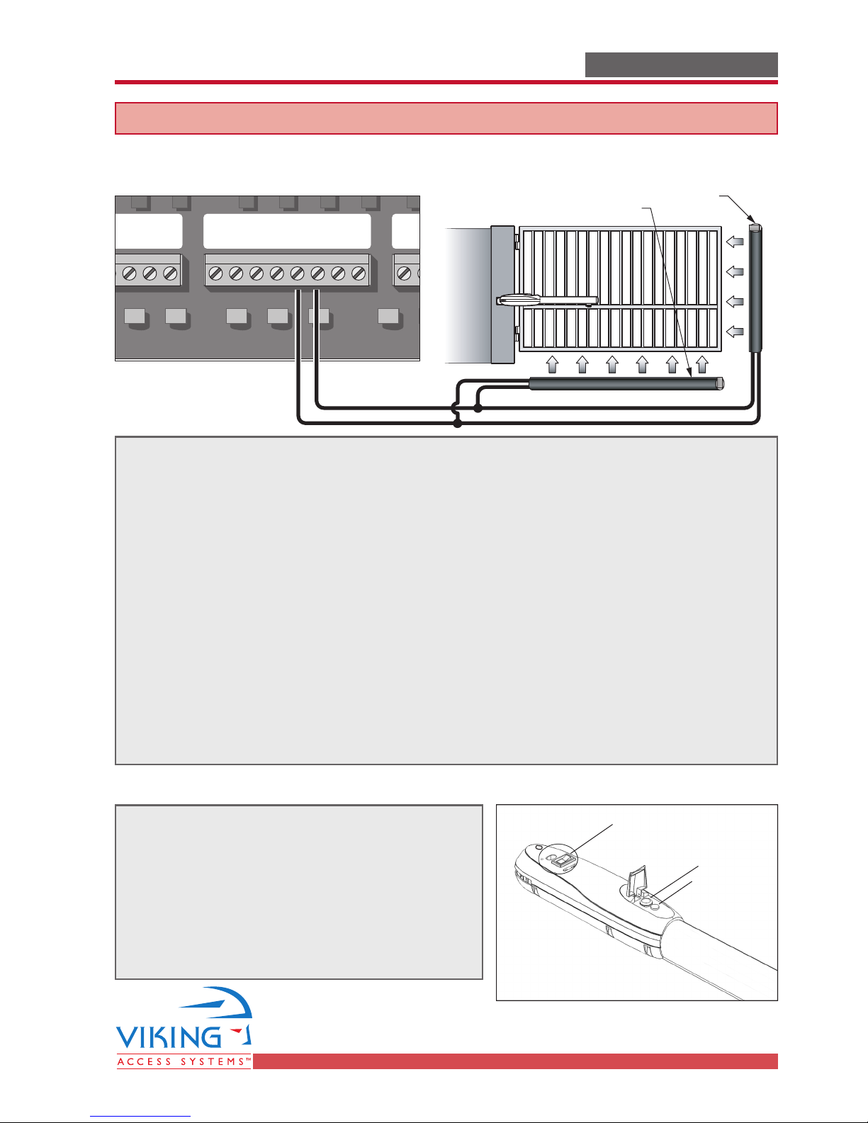
Photo Beam (non-contact sensor) Installation
Secondary Entrapment Protection
Photo beams or like must be installed to reduce the risk of entrapment.
Use only Omron E3K-R10K4 photoelectric eye to comply with UL325
Make the electrical connections of the photoelectric sensor as described here on this page.
Care shall be exercised to reduce the risk of nuisance tripping, such as when a
vehicle trips the sensor while the gate is still moving; and
One or more non-contact sensors shall be located where the risk of entrapmentor
obstruction exists, such as the perimeter reachable by a moving gate or barrier.
Safety Connector
Loop Connector
Position
Gnd
UL
Gnd
Exit
Gnd
Center
Gnd
Reopen
+28v
Gnd
(C1) (NC1)
Photo Beam Unit Reector
Gate in Open Position
One or more non-contact sensors should be located where the risk of entrapment or
Connection '1' (C1)
Connection '3' (NC1)
24 VDC Power Connections
24 VDC Power Connections
Area (Shaded)
(C1) (NC1)
24VDC
24VDC
obstruction exists, such as the perimeter reachable by a moving gate or barrier.
Consult the installation manual of the UL325 device (photo
beam or like) for detail information about the usage,
installation, and maintenance
Shown
6
TECHNICAL SUPPORT 1 800 908 0884
Page 11
Radio Station
Lock
Mag. Lock
Timer
Radio Station
Radio
Gnd
+28v
+28v
Lock
MAG. LOCK
N.C.
COM
N.O.
Timer
30
60
Off
1
IMPORTANT SAFETY INFORMATIONIMPORTANT SAFETY INFORMATION
3-Sided Edge Sensor
3-Sided Edge Sensor
WARNING - Not following these instructions may cause severe injury or death to persons.
Edge Sensor (contact sensor) Installation
Secondary Entrapment Protection
Safety Connector
Loop Connector
Strike
Gnd
Exit
Gnd
Edge sensor or like must be installed to reduce the risk of entrapment.
Use only Miller Edge 3-sided activation type MGR20 or MDS20 to comply with UL325
Center
Gnd
Reopen
GndULGnd
+28v
Gnd
One or more contact sensors shall be located on the inside and outside leading edge
of a swing gate. Additionally, if the bottom edge of a swing gate is greater than 6
inches (152 mm) above the ground at any point in its arc of travel, one or more
contact sensors shall be located on the bottom edge.
1. A hardwired contact sensor shall be located and its wiring arranged so that the
communication between the sensor and the gate operator is not subjected to
mechanical damage.
2. A wireless contact sensor such as one that transmits radio frequency (RF) signals
to the gate operator for entrapment protection functions shall be located where
the transmission of the signals are not obstructed or impeded by building
structures, natural landscaping or similar obstruction. A wireless contact sensor
shall function under the intended end-use conditions.
Manual Release
When manual operation is required:
1. Unlock and remove the Top Cover with the
Key or optional Thumbscrew provided.
2. Place the Manual Release Switch to the
“RELEASE” position.
3. To resume normal operation, place the
Manual Release Switch back to the
“ENGAGE” position.
Manual Release Switch
Key Release
Thumbscrew
TECHNICAL SUPPORT 1 800 908 0884
7
Page 12
IMPORTANT SAFETY INFORMATIONIMPORTANT SAFETY INFORMATION
Open Commands
Sensor
Timer
Stop
Overlap Delay
Close Open
Sensor
min. MAX
Delay
1.5
0
3
Open Commands
Stop
Exit
Timer
Stop
Close
Open
30
60
STOP
WARNING - Not following these instructions may cause severe injury or death to persons.
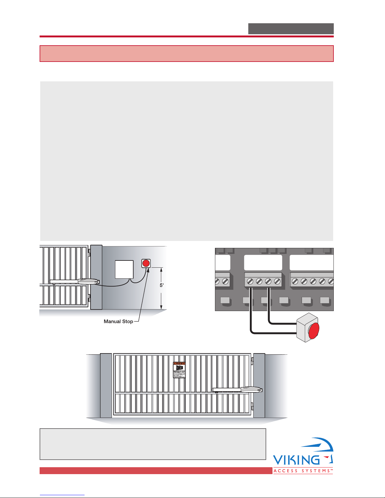
Audible Alarm Reset Switch Installation
Manual Reset for the Audible Alarm
UL325 standard requires an audible alarm to go off after two consecutive events
detected by the primary entrapment protection of the gate operator (obstruction sensor).
The audible alarm will continue to sound for 5 minutes or until a stop command
gets actuated.
The Stop command can be actuated in two different forms:
1. Using the Built in Stop switch on the Control Box; or
2. Using an External Stop button within the sight of the gate, away from moving
parts of the gate and out of reach of children.
3. Controls intended for user activation must be located at least six feet (6’) away
from any moving part of the gate and where the user is prevented from reaching
over, under, around, or through the gate to operate the controls. Outdoor or easily
accessible controls must have a security feature to prevent unauthorized use.
4. The Stop and/or Reset button must be located in the line-of-sight of the gate.
Activation of the reset control must not cause the operator to start.
Guard Station
STOP
Minimum
Button
Warning Placard Installation
Open
Guard Station
GND
Close
Stop
Open
N.O.
COM
Gnd
Fire
Gnd
Strike
Gnd
All Warning Signs and Placards must be installed where visible in the area
of the gate. A minimum of two placards must be installed. A placard is
to be installed in the area of each side of the gate and be visible.
8
TECHNICAL SUPPORT 1 800 908 0884
Page 13
IMPORTANT INSTALLATION INFORMATIONIMPORTANT INSTALLATION INFORMATION
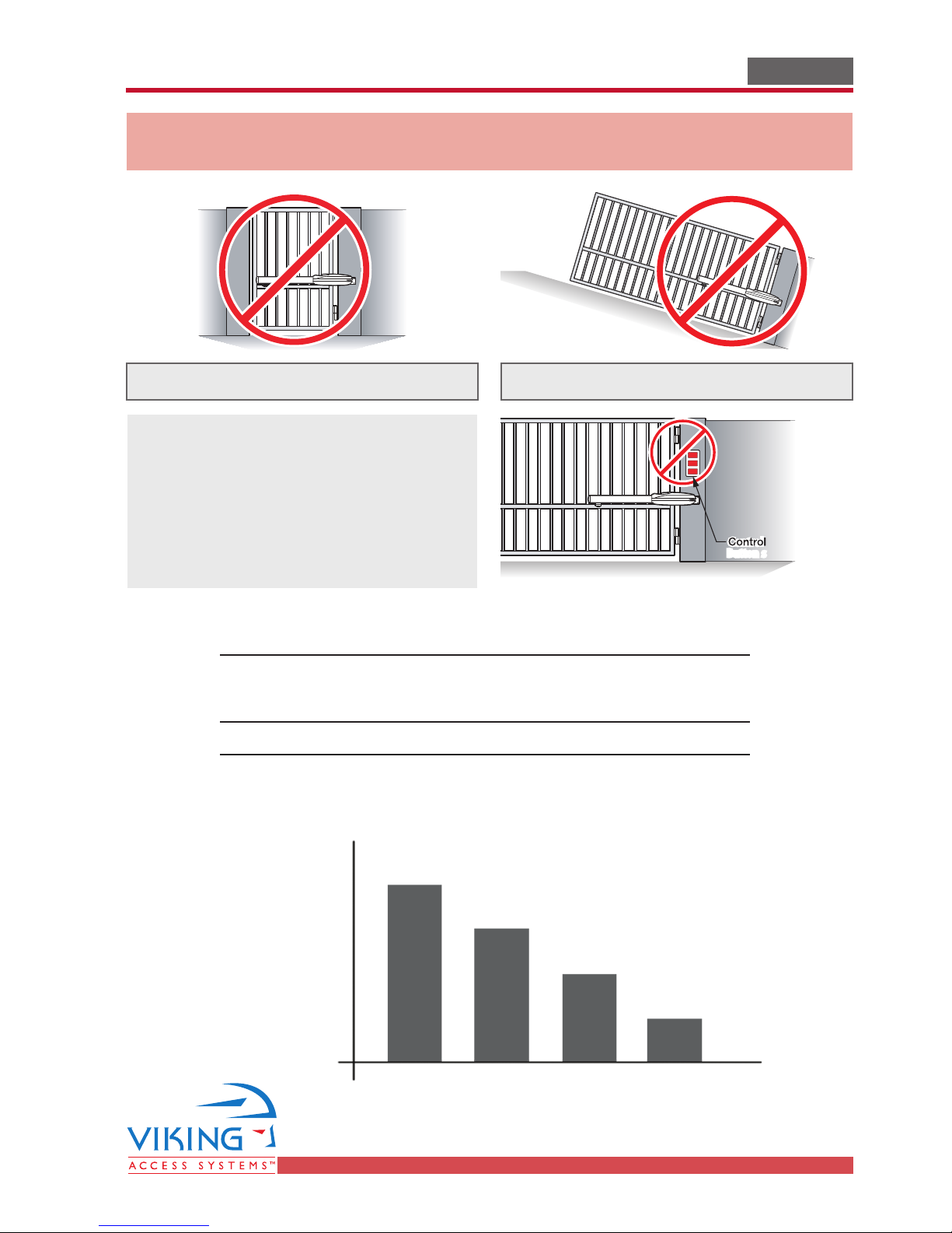
CAUTION -
FOR USE WITH GATES OF A MAXIMUM OF 18 FT. IN LENGTH AND 700 LBS. IN WEIGHT.
WARNING - TO REDUCE THE RISK OF SEVERE INJURY OR DEATH TO PERSONS:
This is NOT a pedestrian gate operator
Locate Control Buttons:
1. Within sight of the gate,
2. At a minimum height of 5 feet so
small children are not able to
reach it; and
3. At Least 6 Feet away from all moving
parts of the gate.
Do NOT Install the gate operator to lift gates
OPEN
STOP
CLOSE
Button sButtons
Specifications
Power Requirements: 120 VAC Single Phase at 2 Amps
Operating Temperature: -20°C (-4°F) to
Maximum Gate Weight/Length: Refer to Chart
2000 lb
1500 lb
1000 lb
800 lb
Or
220 VAC Single Phase at 1 Amp
70°C (158°F)
Lb
Max.
Max.
Max.
Max.
Ft
10’ 12’ 16’ 18’
TECHNICAL SUPPORT 1 800 908 0884
Gate Weight/Length Relationship
9
Page 14
BC
Inside
Outside
Gate in Closed Position
D
90°/ 120°
A
E
Gate in Open Position
Note: Back Mounting Bracket
Must Be Cut to Obtain
Desired Dimension “A”
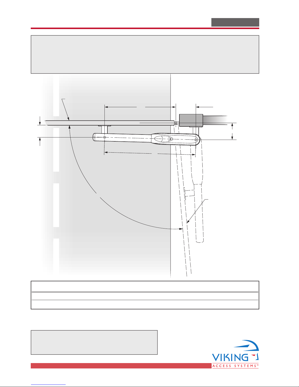
PLAN OF INSTALLATION - OPEN INSIDEPLAN OF INSTALLATION - OPEN INSIDE
The gate must be installed in a location so that enough clearance is supplied
between the gate and adjacent structures when opening and closing to reduce the
risk of entrapment.
Swinging gates shall not open into public access areas.
NORMAL INSTALLATION
Range A B C D E Opening Time
Option A 6.00 4.50 27 31.5 4.75 14 seconds
Option B 6.625 7.875 28 35.875 4.75 20 seconds
Figure A
Open Inside Plan of Installation
Note: Varying from the dimensions shown
may severely affect the speed and
performance of the gate operator.
10
TECHNICAL SUPPORT 1 800 908 0884
Page 15

PLAN OF INSTALLATION – OPEN OUTSIDEPLAN OF INSTALLATION – OPEN OUTSIDE
Inside
Outside
Not a
Not a
Public
Public
Access Area
Access Area
A: 7-7/8"
C:
28"
Custom Plate
Required
(Not Supplied)
90°/ 105°
B:
6-5/8"
E: 4-3/4"
Gate in Open Position
Gate in Closed Position
D:
35-7/8"
The gate must be installed in a location so that enough clearance is supplied
between the gate and adjacent structures when opening and closing to reduce the
risk of entrapment.
Swinging gates shall not open into public access areas.
Figure B
Open Outside Plan of Installation
TECHNICAL SUPPORT 1 800 908 0884
Note: Varying from the dimensions shown
may severely affect the speed and
performance of the gate operator.
11
Page 16

GATE OPERATOR INSTALLATIONGATE OPERATOR INSTALLATION
CAUTION - If Front Mounting Bracket is not welded to a frame member that runs the
full length of the gate, the gate operator may damage the gate. Do not weld the
bracket or backing plate to a few pickets.
STEP 1
Cut and position the Front Mounting Bracket
(offset bar) according to figure A or B found
on page 10 or 11. Tack weld the bracket in
place. Ensure that the bracket is level.
Note: It is recommended to use a frame
member across the full width of the gate.
For gates of non-ferrous construction, a backing plate is provided. The bracket must be cut to
the proper length and welded to the backing plate
if used.
STEP 2
Cut and position the Back Mounting Bracket
(pivot bar) according to figure A or B found
on page 10 or 11. Tack weld the bracket in
place. Ensure that the bracket is level.
Note: For an Open Outside gate, an additional
bracket will need to be fabricated to obtain the
proper configuration (see Figure B, page 11).
A backing plate is also provided if unable to
weld the Back Mounting Bracket to the gate
post or column.
For Location
Level Line
12 16
TECHNICAL SUPPORT 1 800 908 0884
Page 17

GATE OPERATOR INSTALLATIONGATE OPERATOR INSTALLATION
Step 3
Remove the Top Cover and set for Manual
Realease:
a) Open the plastic flap
b) Remove the Top Cover.
c) Place the Manual Release Switch in the
“Off” Position.
STEP 4
Mount the operator and ensure that the gate
and gate operator moves freely.
Once it is determined the operator will work
properly, remove the operator and complete
the welding process.
Place the Manual release switch back to the
“Reset”position.
Movement
STEP 5
Remount the gate operator. Lubricate the
moving parts (the carrier bolt shaft on the
lead screw bar, the large and small washer)
and tighten the self-locking nut.
Note: The Rear Pivot Bushing provided is oil
impregnated and does not require lubrication.
Lead Screw Carrier
Front Mounting Bar
Washer
Washer
TECHNICAL SUPPORT 1 800 908 0884
1317
Page 18

GATE OPERATOR INSTALLATIONGATE OPERATOR INSTALLATION
Limit Switch Setup
STEP 6
Remove the lead screw cover:
a) Remove the screw and
b) Slide out the cover.
STEP 7
Loosen the screws on the limit switch
holders and position the limit switches to
the desired position.
Move the gate manually and ensure that the
limit switch gets actuated at the desired open
Note: Leave cover off until after
the installation of the control box
and the electrical installation.
Verify that the operator opens
and closes to the desired
position under power. Make any
adjustments as necessary.
and closed position. The limit switch will click
when engaged by the lead screw carrier.
Retighten the screws on the limit switch
holders once the proper position has been
determined (DO NOT OVERTIGHTEN).
With the Close Limit Switch properly adjusted
and the gate partially open, install the Positive
Stop Collar onto the shaft in the position shown.
(There should be a 1/16” gap between the
Collar and the Limit Switch Holder). Tighten
the Collar evenly until secure.
Close the gate and check that the gate stops at
the inteneded place. If not, readjust the collar
as necessary and recheck the position after
opening and closing the gate.
STEP 8
Replace the cover taking care to position the
shaft properly inside the endcap.
Align Shaft
with Endcap
Socket
14 18
TECHNICAL SUPPORT 1 800 908 0884
Page 19

O
r
a
n
g
e
Y
e
l
l
o
w
B
l
u
e
B
l
a
c
k
B
r
o
w
n
R
e
d
GATE OPERATOR INSTALLATIONGATE OPERATOR INSTALLATION
Opening/Closing Setup:
To have the gate operator slow down prior to reaching its limits use the following steps:
1. Setup the Limit Switches manually at the desired open and close position.
2. Allow the gate operator to run a full open and close cycle (from limit to limit)
without interruption.
Note: During the first full open and close cycle: The gate operator doesn’t slow
down prior to reaching its limits. During subsequent cycles: The gate operator will
slow down prior to reaching its limits.
3. Verify that the gate opens and closes to the desired position.
To change the open or close limit position(s) the following steps MUST BE taken:
A. Reset the gate operator by performing one of the following steps:
i. Disconnect the Motor/Limit Harness Connector
(see page 18 or 19) or
ii. Actuate both limits at the same time
Slow
B. Repeat steps 1, 2 and 3.
Fast
Slow
Reference Wiring Diagram
Connect the lead wires as shown
From Control Box
Switches
The Limit Switches are wired as shown
Note: Use this wiring
diagram as a guide to
connect the wires to the
motor unit.
To Motor
Limit Switch Connections
Limit Switch
Limit Switch
TECHNICAL SUPPORT 1 800 908 0884
COM
N.O.
N.C.
Yellow
Orange
COM
N.O.
N.C.
Brown
Red
15
Page 20

CONTROL BOX INSTALLATIONCONTROL BOX INSTALLATION
17"
Depth: 6.5"
16"
Mounting Surface
Control Box
Sealed Washer
(Supplied with Unit)
Mounting Fastener
(Customer Supplied)
WARNING - If the control box is not
mounted properly it may fall, causing
damage and/or injury. The Electronic
Control Unit (ECU) weight is
approximately 40 lbs. Be sure that the
substrate being mounted to and the
fasteners being used are appropriate to
support the weight of the control box.
1. Disconnect the Siren and Stop Button
Leads from the Control Board. Remove
the Control Board Mounting Plate. The
plate is held in the box by four screws.
2. Position the ECU Box in the desired place
and mark the mounting holes. Prepare the
holes to receive the anchors/fasteners.
3. Position the ECU Box and secure it to the
mounting surface using the Sealed
Washers provided (place the rubber side
of the washers against the inside of the
control box).
Note: Depending on type of anchor used, it
may be necessary to enlarge the
mounting holes in the control box.
TECHNICAL SUPPORT 1 800 908 0884
1516
Page 21

ELECTRICAL INSTALLATIONELECTRICAL INSTALLATION
Caution – Do not connect the power harness to the board
until the installation is ready for verification.
STEP 4 (Refer to Page 16 for EMI Board Location)
The Gate Operator requires a single phase AC
line to operate the gate and charge the batteries.
A. Turn off the main switch or breaker for
the power line being used.
B. Move the selector switch on the Incoming
Voltage Selector to the proper position
(115 for 110 to 120VAC, 230 for 200 to 240VAC).
C. Connect the incoming power wires to the
terminals as shown in the illustration.
D. Turn on the main switch or breaker once
the installation is ready for final
adjustments.
Verify that all three LEDs are illuminated
E.
on the EMI Board.
Plug the Power Harness in to the Control
F.
Board.
Verify that the “Charger” and “Power” LEDs
G.
are illuminated on the Control Board.
Power Harness
Auxiliary Power Connection.
See page 29 for further details.
White
Green
24VAC
Red
Black
24V BAT
Guidelines for proper ground installation
To minimize the effects caused by lightning,
follow these guidelines.
1. Use a ground rod to provide a ground
reference.
2. Consult your city code and be aware of
underground services in the site of the
gate operator to prevent inconveniences.
3. Always use a single bonding point for
grounding.
4. All ground wires must be as short and as
thick as possible.
5. Prevent unnecessary turns or loops in all
ground wires.
TECHNICAL SUPPORT 1 800 908 0884
Earth Ground
Ground Rod
17
Page 22

ELECTRICAL INSTALLATION – SINGLE UNITELECTRICAL INSTALLATION – SINGLE UNIT
Match
Colors
Radio
UL
OPEN R IGHT
OPEN L EFT
Charger
Charger
Radio
UL
Radio
UL
OPEN R IGHT
OPEN L EFT
Charger
Charger
Radio
UL
Open
Open
Single Unit Connections
Connect the wires from the motor unit to
the terminal block mounted next to the
control board. Match wire colors to the
terminal block.
Connect the wire harness to the “OPEN RIGHT”
connector if the gate opens inside. Connect
the wire harness to the “OPEN LEFT”
connector if the gate opens outside.
Gate opens inside
Gate opens outside
18
Gate opens inside
Gate opens outside
TECHNICAL SUPPORT 1 800 908 0884
Page 23

ELECTRICAL INSTALLATION – MASTER/SLAVEELECTRICAL INSTALLATION – MASTER/SLAVE
Master
Master Open Slave Open
InsideOutside
InsideOutside
Black
Blue
Free
Yellow
Brown
Orange
Red
Master/Slave Connections
A Master/Slave control board is available,
when required, to run two gate operators in
synchronous mode.
Using the connectors provided insert the
wires from the motor units as shown in the
diagram below. Insert the connectors in the
proper receptacles (Master or Slave, Open
Inside or Outside).
TECHNICAL SUPPORT 1 800 908 0884
19
Page 24

Inside
Outside
Exit Loop
Inside Reopen Loop
Center Loop
Outside
Reopen Loop
Inside
Outside
5'
5' 5'
AA
5'
Gate in Open Position
Inside
Reopen
Loop
Center
Loop
Outside
Reopen
Loop
Exit
Loop
Make Even
with Open Gate
VEHICULAR LOOP DETECTOR INSTALLATIONVEHICULAR LOOP DETECTOR INSTALLATION
Note: Not all loops may be necessary
for every installation. Check local
regulations and accepted bestpractice design requirements.
Dimension A – 5’ for Single Gate Operator
6’ for Master/Slave Gate Operator
20
TECHNICAL SUPPORT 1 800 908 0884
Page 25

VEHICULAR LOOP DETECTOR INSTALLATIONVEHICULAR LOOP DETECTOR INSTALLATION
WARNING– Consult the installation i nstructions f rom the loop detector manufacturer. The f ollowing
statements are provided as a guide but different requirements may be r equired by t he
vehicular loop detector manufactu
Guidelines for Vehicular Loop Detector Installation
1. Prevent sharp corners in the geometry of the loop sensor.
2. Install the appropriate number of turns for your loop geometry based on the loop perimeter. Use
Table C (below) as a guide.
3. Use XLP (cross-linked-polyethylene) type of wire. This wire reduces the effects of moisture and
other environmental events in altering the functionality of the vehicular loop detector.
4. Twist the lead wire at least 6 turns per foot.
5. Use BACKER-ROD to minimize damage to the loop detector wire prior to using the sealant.
6. Place the loop detector wire and adjust the sensitivity of the vehicular loop detector unit in a
way to minimize the effects of the gate over the loop detector wire.
IMPORTANT – Some of the following parameters may affect the proper functionality of the
vehicular loop detector (consult the installation manual and the manufacturer of the
vehicular loop detector).
• Gate size
•
Number of turns in the loop sensor wire;
• Distance from the loop sensor wire to the gate either at the open or close position.
rer.
Saw Cut
1" Min.
Sealant
Backer-Rod
(3 Turns Shown)
Continuously Wind Wire
in Loop Slot for the
Required Number of Loops
(2 Loops Shown)
Table C – Recommended Number of Turns
Perimeter in Feet Number of Turns
10 5
20 4
30-40 3
50-100 2
Provide Additional Saw Cuts
to Eliminate Sharp Corners
1/8" to 1/4" Saw Slot
Twist Wire Outside the
Loop 6 Twists/Foot
Until Its Connection
to the Loop Detector
TECHNICAL SUPPORT 1 800 908 0884
21
Page 26

ACCESSORY CONNECTIONSACCESSORY CONNECTIONS
Radio Station
Mag.
Lock
Mag. Lock
Safety ConnectorOpen CommandsGuard StationMaster/Slave
Radio
Rec.
UL
Sensor
OPEN R IGHT
24V BAT 24VA C
OPEN L EFT
Safety
Loop
Center
Loop
Obstruction
Sensor
Charger
Power
Low Battery
Motor Sensor
Hold Open
Timer
Stop
Overlap Delay
Obstruction
Sensor
min. MAX
Overlap
Delay
1.5
0
3
Radio StationLoop ConnectorOpen CommandsGuard StationMaster/Slave
Stop
Open
Gnd
Fire
Gnd
Strike
Gnd
Exit
Gnd
Center
Gnd
Reopen
GndULGnd
+28v
Gnd
Radio
Gnd
+28v
+28v
Mag.
Lock
Fail
Safe/Secure
MAG. LOCK
N.C.
COM
N.O.
Charger
Power
Low Battery
Check Motor
Hold Open
Timer
Stop
Open
30
60
Off
1
Radio
Rec.
UL
Sens
Reopen
Loop
Center
Loop
Exit
Loop
Detector
Fire
Override
Keypad
FIRE
Radio Station
Mag.
Lock
Mag. Lock
Safety ConnectorOpen CommandsGuard StationMaster/Slave
Radio
Rec.
UL
Sensor
OPEN R IGHT
24V BAT 24VA C
OPEN L EFT
Safety
Loop
Center
Loop
Charger
Power
Low Battery
Motor Sensor
Timer
Radio StationLoop ConnectorOpen CommandsGuard StationMaster/Slave
Gnd
Exit
Gnd
Center
Gnd
Reopen
GndULGnd
+28v
Gnd
Radio
Gnd
+28v
+28v
Mag.
Lock
Fail
Safe/Secure
MAG. LOCK
N.C.
COM
N.O.
Charger
Power
Low Battery
Check Motor
Timer
30
60
Off
1
Radio
Rec.
UL
Sens
Reopen
Loop
Center
Loop
Radio Station
Mag.
Lock
Mag. Lock
Safety ConnectorOpen CommandsGuard StationMaster/Slave
Radio
Rec.
UL
Sensor
OPEN R IGHT
24V BAT 24 VA C
OPEN L EFT
Safety
Loop
Center
Loop
Charger
Power
Low Battery
Motor Sensor
Timer
Radio StationLoop ConnectorOpen CommandsGuard StationMaster/Slave
Gnd
Exit
Gnd
Center
Gnd
Reopen
GndULGnd
+28v
Gnd
Radio
Gnd
+28v
+28v
Mag.
Lock
Fail
Safe/Secure
MAG. LOCK
N.C.
COM
N.O.
Charger
Power
Low Battery
Check Motor
Timer
30
60
Off
1
Radio
Rec.
UL
Sens
Reopen
Loop
Center
Loop
Center
Loop
Detector
Reopen
Loop
Detector
Photo
Beam
Edge Sensor
Photo
Beam
1
2
Inside
Outside
Connection Locations
(Single Unit Board shown)
Vehicle loop detectors must be installed to
decrease the possibility of vehicle
entrapment on the gate (see page 20).
The SECONDARY ENTRAPMENT
PROTECTI
the photoelectric beam MUST BE PART
OF EVERY SINGLE INSTALLATION to
prevent pedestrian or animal
entrapment (see pages 6 and 7).
ON like the edge sensor and
Open Commands
1
Safety Connections
The edge sensor and/or the photoelectric
beam must be UL325 compliant devices.
Reopen Photo Beam
22
2
As an alternative to the Outside Reopen Loop,
a photo beam unit can be used as shown.
TECHNICAL SUPPORT 1 800 908 0884
Page 27

Lock
Mag. Lock
Rec.Sensor
OPEN RIGHT
24V BAT 24VAC
OPEN LEFT
Charger
Power
Low Battery
Motor Sensor
Lock
F
MAG. LOCK
N.C.
Charger
Power
Low Battery
Check Motor
Rec.
Sens
Loop
ACCESSORY CONNECTIONSACCESSORY CONNECTIONS
Radio Receiver
When connecting the Radio Receiver, carefully verify the proper connections.
The maximum voltage that the control board provides for external accessories, is the
maximum voltage of the battery which is about 28 volts.
In the event of an electrical short in the power to the accessories, the board will
protect itself by shutting down and will remain shut down until the short is corrected.
The control board provides two modes of
operation that a radio receiver can control
the gate:
Open-Stop-Close
1. By having the radio receiver connected as
illustrated and with the Hold Open Timer
OFF (see page 27):
Every command of the radio transmitter
will control the gate as follows:
a) First command opens the gate
b) Second command stops the gate
c) Third command closes the gate
d) Any subsequent commands will continue
NOTE: This type of configuration is not
recommended for commercial applications.
Open Only
2. By having the radio receiver connected as
illustrated and with the Hold Open Timer
ON (see page 27):
Each command of the radio transmitter is
ALWAYS AN OPEN COMMAND to the gate.
in the same order to control the gate.
GndULGnd
+28v
COM
N.O.
Radio Station
Radio Station
Gnd
Radio
+28v
Gnd
+28v
Note: All controls are normally open.
TECHNICAL SUPPORT 1 800 908 0884
COM
NO
Gnd
+24VDC
Accessories
23
Page 28

This page is intentionally left blank.
24
TECHNICAL SUPPORT 1 800 908 0884
Page 29

Open Commands
Loop
Sensor
Timer
Stop
Overlap Delay
Close Open
Sensor
min. MAX
Delay
1.5
0
3
Open Commands
Exit
Gnd
Timer
Stop
Close
Open
30
60
Off
1
ACCESSORY CONNECTIONSACCESSORY CONNECTIONS
OPEN R I GH
Charger
Power
Low Battery
Motor Sensor
Charger
Power
Low Battery
Check Motor
OPEN R I GHT
24V B AT 24VAC
Charger
Power
Low Battery
Motor Sensor
Charger
Power
Low Battery
Check Motor
Magnetic Lock
External supply for the magnetic lock must
be provided. This will prevent rapid drainage
of the battery in the event of power failure.
Relay Contact 10A-250VAC
2 1
Connection Locations
(Single Unit Board shown)
1
Lock
Radio Station
Radio Station
Lock
N.C.
COM
N.O.
Mag. Lock
MAG. LOCK
Solenoid Connection
External supply for the solenoid connection
must be provided. This will prevent rapid
drainage of the battery in the event of
power failure.
Relay Contact 10A-250VAC
Guard Station
The guard station provides control of the
gate operator to open, stop, and close the
gate.
All three switches must be a Normally Open
type of switch and can share the same
common (ground).
Place the control switch box within sight of
the gate, away from moving parts of the
gate and out of reach of children.
1
Lock
Lock
N.C.
COM
N.O.
Mag. Lock
MAG. LOCK
Radio Station
Radio Station
Open
Guard Station
Guard Station
GND
Close
Stop
Open
Gnd
Fire
Gnd
Strike
Gnd
2
N.O.
N.O.
OPEN
STOP
TECHNICAL SUPPORT 1 800 908 0884
N.O.
COM
CLOSE
2524
Page 30

Radio
Rec.
UL
Sensor
24V BAT 24VAC
OPEN LEFT
Safety
Loop
Center
Loop
Obstruction
Sensor
Charger
Power
Low Battery
Motor Sensor
Obstruction
Sensor
min. MAX
Delay
1.5
0
3
Fail
Safe/Secure
Charger
Power
Low Battery
Check Motor
Radio
Rec.
UL
Sens
Reopen
Loop
Center
Loop
SPECIAL FEATURESSPECIAL FEATURES
Intelligent Obstruction Sensor
Trim Pot Location
(Single Unit Board shown)
The Obstruction Sensor detects obstructions
in the path of the traveling gate. The Trim
Pot for the Obstruction Sensor adjusts the
sensitivity level that triggers the Sensor.
When the Obstruction Sensor detects an
obstruction it will:
(Primary Entrapment Protection)
Turning the Trim Pot clockwise
increases the sensitivity.
Turning the Trim Pot counterclockwise decreases the sensitivity.
1. Stop the gate’s movement and reverse it
momentarily.
2. Bring the gate to a resting position.
3.
Disable the Hold Open Timer feature until the
Gate Operator receives a new command.
If another obstruction is detected before the
gate reaches either limit it will:
1. Stop the gate’s movement.
2. Bring the gate to a resting position.
3. Disable the Gate Operator.
UL325 standard requires an audio alarm to
go off after two consecutive entrapment
events
Protection of the Gate Operator.
The audio alarm will sound for a period of 5
minutes or until the “Stop” Button is
pressed (see page 8 for remote installation
of a “Stop” Button).
sensed by the Inherent Entrapment
26 25
TECHNICAL SUPPORT 1 800 908 0884
Page 31

SPECIAL FEATURESSPECIAL FEATURES
Lock
Mag. Lock
Rec.Sensor
OPE N RIGHT
24V BAT
24VAC
OPE N LEFT
LoopLoop
Sensor
Charger
Power
Low Battery
Motor Sensor
Sensor
min. MAX
Delay
1.5
0
3
Lock
Safe/Secure
N.C.
COM
N.O.
Charger
Power
Low Battery
Check Motor
Rec.
Sens
Loop
Loop
Fail Safe/Fail Secure Operation
1
2
Connection Locations
(Single Unit Board shown)
Fail Safe Mode:
By removing the wire-jumper plug
from the “Fail Safe/Secure” connector:
The gate can move mannually with
a relatively low amount of force.
Fail Secure Mode:
By inserting the wire-jumper plug into the
“Fail Safe/Secure” connector:
The gate still move manually, but with
a relatively high amount of force.
The gate operator contains a unique design that
allows the user to move the gate manually in case
of COMPLETE POWER FAILURE.
There are two levels of force required to move
the gate manually.
F
Safe/Secure
1
FT
Manual Release
Note:
If Fail Secure Mode is selected, the gate can
be manually operated with a relatively low
amount of force by peforming the steps
for manual release as outlined at on page 7.
Hold Open Timer
Timer
Open
Open
Timer
60
30
1
Off
2
The Hold Open Timer function holds the gate at
the open position for a predetermined amount
of time, prior to closing automatically.
Set the Timer to the desired time, from 1 to
60 seconds.
If this feature is not needed, turn the Trim
Pot clockwise to the “off” position.
Note: The Hold Open Timer affects the “radio
receiver command” and the sequence of
operation for the gate (see page 23).
TECHNICAL SUPPORT 949-753-1279
TECHNICAL SUPPORT 1 800 908 0884
27
Page 32

SPECIAL FEATURESSPECIAL FEATURES
Inside
Outside
Opens First
Slave UnitMaster Unit
Radio
Rec.
UL
Sensor
Safety
Loop
Charger
Power
Low Battery
Slave
Limit Open
Limit Close
Slave
Limit Open
Limit Close
Obstruction
Sensor
Overlap Delay
1.5
Center
Loop
Hold Open
03
Gate Overlap Setting
Setting the Overlap Delay Pot to “0” will cause the master and the slave units to
open and close at the same time
A Master/Slave control board is required to
operate two gates with a single controller.
Trim Pot Location
(Master/Slave Unit Board shown)
Setting the Overlap Delay Pot to any value
other than zero will cause the master unit to
delay in opening.
The time delay can be set for up to 3 seconds.
28 27
TECHNICAL SUPPORT 1 800 908 0884
Page 33

SPECIAL FEATURESSPECIAL FEATURES
OPEN RIGHT
24V BAT 24VAC
OPEN LEFT
SensorLoopLoop
Sensor
Overlap Delay
Sensor
Delay
1.5
Safe/Secure
Sens
Loop
Loop
Auto-Open Feature
The Auto-Open feature in Viking Gate Operators enables the following functionality in
the event of power failure:
a) Open the gate in case of power failure (120 or 220 VAC).
b) Keep the gate at the open position as long as the there is no power.
c) Resume to normal operation when the power has been restored.
The Auto-Open feature allows proper operation while opening in case of power failure
for the following devices:
• All accessories,
• All safety devices,
• All entrapment protections.
The only operation that can not be executed while opening in case of power failure is to
CLOSE the gate.
To enable the Auto-Open feature : Use the
“jumper” provided and place it on the pin-
JP3
header of JP3, on the terminals close to C35 as
the illustration indicates.
C35 C36
Once you put the “jumper” on the control
board the “Check Motor” light will come on
Charger
Charger
Rec.
Sens
Rec.
Power
Power
Low Battery
Low Battery
Motor Sensor
Check Motor
indicating that the Auto-Open feature has been
enabled.
OTE: This feature is NOT available on the Master/
N
Slave (Dual) Control Board.
Lock
TECHNICAL SUPPORT 1 800 908 0884
29
Page 34

OPTIONALSOLAR PANEL INSTALLATIONOPTIONAL SOLAR PANEL INSTALLATION
Radio Station
Mag.
Lock
Mag. Lock
Safety ConnectorOpen CommandsGuard StationMaster/Slave
Brake
UL
Siren
Radio
Rec.
UL
Sensor
OP E N R I GHT
24V BAT 24 VAC
OP E N L E FT
Safety
Loop
Center
Loop
Obstruction
Sensor
Charger
Power
Low Battery
Motor Sensor
Hold Open
Timer
Stop
Overlap Delay
Close Open
Obstruction
Sensor
min. MAX
Overlap
Delay
1.5
0
3
Radio StationLoop ConnectorOpen CommandsGuard StationMaster/Slave
GND
Close
Stop
Open
GND
Close
Stop
Open
Gnd
Fire
Gnd
Strike
Gnd
Exit
Gnd
Center
Gnd
Reopen
Gnd
UL
Gnd
+28v
Gnd
Radio
Gnd
+28v
+28v
Mag.
Lock
Fail
Safe/Secure
MAG. LOCK
N.C.
COM
N.O.
Charger
Power
Low Battery
Check Motor
Hold Open
Timer
Stop
Close
Open
30
60
Off
1
Radio
Rec.
UL
Sens
Reopen
Loop
Center
Loop
Brake
Siren
JP3
C35 C36
+ –+ –+ –
+
–
+
–
Solar Input Battery Input Load Input
For Viking Vehicular Gate Operators
Connect the Solar Panel
Controller as shown.
Use one 24V 80W
solar panel or two
12V 40W solar panels.
Remove the existing
Power Harness and
use the power
harness provided.
Remove existing batteries. Use new
external batteries of 35 AHr or
greater and connect them in series to
provide a 24V system.
30
TECHNICAL SUPPORT 1 800 908 0884
Page 35

OPTIONALSOLAR PANEL INSTALLATIONOPTIONAL SOLAR PANEL INSTALLATION
Radio Station
Mag.
Lock
Mag. Lock
Safety ConnectorOpen CommandsGuard StationMaster/Slave
Brake
UL
Siren
Radio
Rec.
UL
Sensor
OP E N R I GHT
24V BAT 24 VAC
OP E N L E FT
Safety
Loop
Center
Loop
Obstruction
Sensor
Charger
Power
Low Battery
Motor Sensor
Hold Open
Timer
Stop
Overlap Delay
Close Open
Obstruction
Sensor
min. MAX
Overlap
Delay
1.5
0
3
Radio StationLoop ConnectorOpen CommandsGuard StationMaster/Slave
GND
Close
Stop
Open
GND
Close
Stop
Open
Gnd
Fire
Gnd
Strike
Gnd
Exit
Gnd
Center
Gnd
Reopen
Gnd
UL
Gnd
+28v
Gnd
Radio
Gnd
+28v
+28v
Mag.
Lock
Fail
Safe/Secure
MAG. LOCK
N.C.
COM
N.O.
Charger
Power
Low Battery
Check Motor
Hold Open
Timer
Stop
Close
Open
30
60
Off
1
Radio
Rec.
UL
Sens
Reopen
Loop
Center
Loop
Brake
Siren
JP3
C35 C36
Connect Leads from
Solar Panel(s), Polarity
is not important
Cut the Leads
to the Toroidal
Transformer
+
–
+
+
–
–
Reuse Existing
Battery Fuse Holder
Connect New
Batteries to
Existing Leads
Observing Polarity
Red Wire
Black Wire
+
–
+
–
Connect To Gate
Operator Input Block
24 VDC
Panel
12 VDC
Panels
2
*With a 80 Watt (24VDC) Panel System.
5
8
10
12
14
Number of
Cycles per Day*
January July
For Viking Vehicular Gate Operators
WWAARRNNIINNGG––SSoollaarr PPaanneell mmuusstt bbee UULLLLiisstteedd,, CCllaassss 2
2
STEP 1
Use a 24V solar panel or two solar panels of 12V
in series with a total capacity of 80 Watts..
STEP 2
Connect the solar panel cables to the power
harness as shown. Make sure you cut the wires
coming from the toroidal transformer.
STEP 3
Replace the existing batteries with a battery pack
of 35AHr or greater.
STEP 4
Refer to the maps provided to get an idea about the
number of cycles the gate will be operated per day.
This figure is for a single gate operator with just:
a) One Radio reiver,
b) One low voltage low current loop detector and
c) One low voltage, low current photo cell
1.
The greater capacity of the batteries, the longer the system will operate on cloudy days.
2. If more specific information is needed, please consult with Viking Access Systems.
For more information regarding solar energy refer to http:/www.nrel.gov.
TECHNICAL SUPPORT 1 800 908 0884
31
Page 36

VIKING PIPE STANDVIKING PIPE STAND
Part No. VA-G5PSKT
For Viking G-5 Vehicular Gate Operator
Standard Features
• Main pieces made of 1/4” thick material
• All hardware included
When installing the Pipe
Stand Assembly be sure it is
parallel to the gate and that
it is level. For further details
see the G-5 installation
manual.
Grade Level
3-1/2" Pipe
(4.00" OD)
Consult Local Codes
for Depth and Concrete
Requirements
4" Square Pipe
6" Square Pipe
G-5 Gate Operator
(sold separately)
32
Note:
All Mounting Hardware
Supplied with Pipe Stand
TECHNICAL SUPPORT 1 800 908 0884
Page 37

C
Inside
Outside
Gate in Closed Position
90°/ 120°
A
E
Gate in Open Position
3-1/2" (4.00" OD) Round Pipe
Open Left
4" Square Pipe
Open Left
3-1/2" (4.00" OD) Round Pipe
Open Right
4" Square Pipe
Open Right
6" Square Pipe
B
D
PLAN OF INSTALLATION - OPEN INSIDEPLAN OF INSTALLATION - OPEN INSIDE
The gate must be installed in a location so that enough clearance is supplied
between the gate and adjacent structures when opening and closing to reduce the
risk of entrapment.
Swinging gates shall not open into public access areas.
NORMAL INSTALLATION
Range A B C D E Opening Time
Minimum 6.00 5.00 27 31.50 4.75 14 seconds
Maximum 7.00 7.875 28 35.875 4.75 20 seconds
Figure A
Open Inside Plan of Installation
Note: Varying from the dimensions shown may severely affect
the speed and performance of the gate operator.
TECHNICAL SUPPORT 1 800 908 0884
33
Page 38

OPTIONAL VIKING BLUE INSTALLATIONOPTIONAL VIKING BLUE INSTALLATION
OPEN RIGHT
24V BAT 24VAC
OPEN LEFT
Charger
Charger
Power
Low Battery
Check Motor
Rec.
Radio Station
Open Commands
Guard Station
Master/Slave
Obstruction
Sensor
min.
MAX
Overlap
Delay
1.5
0
3
3
Radio Station
Loop Connector
Open Commands
Guard Station
Master/Slave
GND
Close
Stop
Open
GND
Close
Stop
Open
Gnd
Fire
Gnd
Strike
Gnd
Exit
Gnd
Center
Gnd
Reopen
Gnd
UL
Gnd
+28v
Gnd
Radio
Gnd
+28v
+28v
MAG. LOCK
COM
N.O.
Hold Open
Timer
Stop
Stop
Close
Open
Open
30
60
Off
1
Reopen
Center
Loop
Brake
Siren
JP3
C35
C36
JP2
Match up
Match up
White Dots
White Dots
Match up
White Dots
Install
Install
Jumper
Jumper
Install
Jumper
JP2
JP2
JP2
If you are using the computer:
• Hold the computer near the Gate
• Run the application by clicking the
Operator.
icon on the desktop.
• Select “Setting” in the top right of the
screen.
If you are using a PDA:
• Hold the PDA near the Gate Operator.
• Select “Start” and “Programs”.
• Click the Viking-Blue Application.
• Select “Connection” on the toolbar.
34 31
1. Insert CD into host computer
2. Install MS ActiveSync (check your
computer, it may already be installed to
communicate with a PDA or smart phone.
3. Install Viking Blue software
Select Install Viking-Blue for PC (to have the
computer to communicate with the Operator)
Select Install Viking-Blue for PDA (to have
the PDA to communicate with the Operator)
WARNING: If this PDA is a new device, turn off
all options when syncing with the computer.
For either installation, follow the steps in the
user manual.
4. Plug the Viking Blue Module into the Viking
Gate Operator Control Board.
WARNING: Connecting the plug backwards can
result in damage to the Control Board and
will render the Viking Blue Module useless.
Use care in connecting the plug to the Control
Board. The pins are small and easily bent.
Match the white dot on the plug to the white
dot on the control board (near the JP2 legend
as depicted).
5. Install the Jumper (near the JP3 legend
depicted). Viking-Blue requires this jumper
to operate. The “Low Battery” LED will turn
ON, indicating the Control Board is ready for
use with the Viking-Blue Module.
6. Open Viking Blue software on the chosen
device.
• Click “Search” (looking for available
Viking devices).
• Select the Operator you want to
communicate with.
• Click “Connect” to start communication.
The Light on the Viking-Blue module
will turn green upon connection to the
Computer or PDA.
Follow the steps in the user manual.
TECHNICAL SUPPORT 1 800 908 0884
Page 39

TROUBLESHOOTINGTROUBLESHOOTING
Gate does not run – Motor Sensor indicator comes ON
Check all motor connections to
be fully engaged. Refer to page
15, 18 and 19.
Check the 15 Amp fuse in the
control board
Ensure that the motor
connections are:
a) Properly connected,
b) Tight enough and
c) Color coded
Refer to page 15.
Ensure that the Manual Release Switch is
in the “ENGAGE” position. Refer to page 7.
Gate does not run – Motor Sensor indicator is OFF
Check all motor connections to
be fully engaged. Refer to 15.
Check that the UL command
(photo beam and/or edge
sensor) is not active. Refer to
page 6, 7 and 22.
Ensure that you external accessories are working properly.
Check that limit switches are
connected to the common and
the normally close position
refer to page 15.
Check that the vehicular loop
detectors are working properly.
Refer to page 20, 21 and 22.
Check the 4 Amps fuse in the
control board
Check that all motor cable
connections, junctions and
extensions are properly
connected and color-coded.
Refer to page 15.
Check that the stop command
is not active. Refer to page 8
and 25
Check that the radio command
is not active. Refer to page 23.
Ensure that you power cables are
adequate in voltage and properly
connected. Refer to page 17.
Gate does not run – Power failure
Check the 15 Amp battery fuse.
Refer to page 16
Check the battery connections
and cables.
Check the voltage of the
battery.
Gate does not run – Obstruction sensor ON and audio alarm is SOUNDING
Ensure that the gate path is
clear of obstructions.
Note: To stop the audio alarm,
use the stop command. Refer
to page 8 and 25.
Adjust the trim pot of the
obstruction sensor. Refer to
page 26.
Gate runs, stops and reverse momentarily – Obstruction sensor ON and audio alarm OFF
Ensure that the gate path is
clear of obstructions.
Check for proper functionality
and lubrication of the gate and
hardware (hinges and the like).
Adjust the trim pot of the
obstruction sensor. Refer to
page 26.
Gate ignores the limit switches
Check that the open limit
switch and close limit switch
are in the corresponding place.
Refer to page 15.
Check that the limit switch is
not faulty
Check that all motor cable
connections, junctions and
extensions are properly connected and color-coded. Specifically
check the blue and black motor
leads. Refer to page 15.
Check that wires to the limit
switch are not shorted.
Ensure that the motor cable is
away from sources of electrical
interference, such as
a) Electric motors
b) Electric fences
c) Power lines
Note: To minimize effects
cause by electrical interference
use twisted pairs of cables with
the shield grounded.
TECHNICAL SUPPORT 1 800 908 0884
3532
Page 40

TROUBLESHOOTINGTROUBLESHOOTING
Gate does not open or close
Check all motor connections to
be fully engaged. Refer to page
15.
Check that the UL command
(photo beam and/or edge
sensor) is not active. Refer to
page 6, 7 and 22.
Ensure that you external
accessories are working
properly
Check that limit switches are
connected to the common and
the normally close position
refer to page 15.
Check that the vehicular loop
detectors are working properly.
Refer to page 20, 21 and 22.
Ensure that the Manual Release
Switch is in the “ENGAGE” position.
Refer to page 7.
Automatic Hold Open Timer does not function
Check that the trim pot of the
hold open timer is set to the
proper time delay. Refer to
page 27.
Note: Hold open timer closes
the gate automatically once the
gate reaches the limit open.
The time delay to close is set
by the trim pot.
To turn this system off turn the
trim pot all the way clockwise.
Gate opens in the opposite desired direction
Check that the stop command
is not active. Refer to page 8
and 25.
Check that the radio command
is not active. Refer to page 23.
Verify proper functionality of:
Photo beam(s)
Loop Detectors
Radio Receiver
that may prevent closing the
gate.
Verify your motor cable is
connected to the proper
connector. Specifically check
the blue and black motor leads.
Refer to page 18 and 19.
Check that all motor cable
connections, junctions and
extensions are properly
connected and color-coded.
Refer to 15.
Gate opens in the opposite desired direction passing the limit switch
Check the motor wiring and
polarity of cables. Refer to
page 18 and 19.
On a Master/Slave installation, one gate runs in the opposite direction
Check the motor and limit
switch wiring. Refer to page 15
and 19.
Verify that both units are
connected as open-left or
open-right. Refer to page 19.
36 33
TECHNICAL SUPPORT 1 800 908 0884
Page 41

TROUBLESHOOTINGTROUBLESHOOTING
Gate opens after few second delay
Set the overlap delay trim pot
to 0. Refer to page 28.
Note: Overlap trim pot is
normally recommended to use
in overlapping gates. Refer to
page 28.
Gate opens. Closes or stops on its own
Ensure that the key for manual
release is in the lock position.
Refer to page 7.
Make sure that the ‘Charger’
LED is on, indicating that there
is AC power.
G-5 unit runs slower than normal
Set the overlap delay trim pot
to 0. Refer to page 28.
Note: Overlap trim pot is
normally recommended to use
in overlapping gates. Refer to
page 28.
‘Charger’ LED off. Gate does not run - alarm sounds upon any input command
Check the 4 Amp fuse on the
control board.
Check the 3 Amp fuse on the
EMI control board. Refer to
page 17.
Make sure the incoming AC
line is properly connected.
Refer to page 17.
Check the incoming high
voltage power supply.
Check that all three LED
indicators on EMI board are
illuminated. Refer to page 17.
Check the proper selection of
power supply (120/220 VAC).
Refer to page 17.
Green LED - Input Power
On - Indicates OK
Off - Check the power to EMI Board
Yellow LED - Output Power
On - Indicated OK
Off - Check 6 Amp fuse on EMI Board
Red LED - Protection
On - Indicates the circuit is protected
Off - Circuit is not protected. Replace EMI Board
for continued protection against surge and lightning.
Verify the EMI board by
reading high voltage across the
(4) blue and red wires at the
terminal block connections.
Battery voltage reads zero or very low
Ensure the batteries are connected as follows:
a) Left battery - Black terminal connected to the black wire from the harness (jacketed wire)
b) Left battery - Red terminal connected to the red wire from the fuse holder.
c) Right battery - Black terminal connected to the red wire from the fuse holder.
d) Right battery - Red terminal connected to the red wire from the harness (jacketed wire)
TECHNICAL SUPPORT 1 800 908 0884
37
Page 42

Notes
Page 43

OUR CONTINUOUS COMMITMENT TO EXCELLENCE
Viking Access Systems is continuously working hard to identify and
design products that will appeal to the industry and it’s needs. As
technology continues to advance, we have developed a completely
efcient and intelligent line of gate operators to meet the changing
demands. These machines offer; full UL325 and UL991 compliance,
soft-start and soft-stop, intelligent obstruction sensors, continuous
operation (100% duty cycle) and extreme power efciency. Innovative
features include; adaptive and self-learning algorithms, redundancy
design in both hardware and software to ensure operation and
functionality, protection from lightning, short circuit and power surges,
and our exclusive helical gearing offering the highest efciency rating
in the industry. Our entire product line is continually modied and
improved based on the latest technology and our customer’s valuable
feedback. The results are products that offer accuracy, efciency,
reliability and performance, all in sleek, high-tech designs.
We pledge to continue establishing ourself as the leader in high quality,
innovative gate operators by developing “Next Level” technology. We
are committed to providing safety and convenience with innovative
solutions for every security gate need.
Page 44

STANDARD FEATURES
AND OPERATOR SPECIFICATIONS
• UL325 and UL991 Compliant by Underwriter
Laboratories (UL) standards.
• Manual Release switch
• Fail-Safe option sets the gate to
automatically transfer to a fail-safe mode
in the event of a power failure, allowing the
gate to be pushed open without the use of
special knowledge of the equipment
• Fail- Secure option sets the gate to
electronically lock in the event of a power
failure, allowing no manual movement
without the use of the manual release
• Elegant design, appealing to any
architectural project
• Powder coated aluminum housing
• Opening up to 135°
• Operation speed of 15 to 18 seconds per 90°
• 100% duty cycle
• Very low power consumption
• 400 cycles of operation on backup battery
(600 lb. gate and 12’ length)
• Intelligent speed control with smooth start
and stop, self-adjust system
• Modulated speed regulator prevents
exceeding operating speed that may reduce
the service life of the gate operator and/or
installation
• Intelligent obstruction detection with
adjustable sensitivity
• Overlap delay that holds one gate
momentarily by an adjustable time while
the other gate is operating (Master/Slave
installation with overlap gates)
• Built-in protection against lightning strikes
or similar electrical surges
• Inherent overload protection in the regulated
power supply for external accessories with
multiple devices of protection
• Modular connectors for easy access control
installations
• Solar panel and low voltage wiring
compatibility
• LED indicators display gate and operator
status for easy troubleshooting
INS TA L L ATION DATE : __________________________________
COMPANY / INSTALLER: ________________________________
CO N TACT: __________________________________________
SERIAL NUMBER(S): ____________________________________
ALL INSTALLATION, MAINTENANCE AND REPAIR WORK MUST BE
DOCUMENTED AND MADE AVAILABLE TO THE USER.
VIKING ACCESS SYSTEMS
631 Wald Irvine, CA 92618
Phone 800.908.0884
Fax 949.753.1640
www.vikingaccess.com
 Loading...