

Page 1
INSTALLATION
INSTRUCTIONS
AND SAFETY INFORMATION
RESIDENTIAL
CLASS I VEHICULAR SWING GATE OPERATOR
Page 2
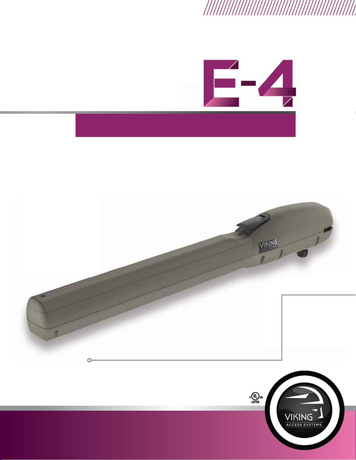
The new E-4™Residential Swing Gate Operator leads the industry in being the best, most cost eective
residential linear arm actuator. This new design allows for a maximum gate capacity up to 850 lbs/10’ or
550 lbs/16'. Featuring one Control Board for both Single and Dual gate applications, a convenient manual
release handle and pre-wired for aneasy and quick installation. It is ready to be powered with low voltage
wiring, allowing installation versatility and accuracy.
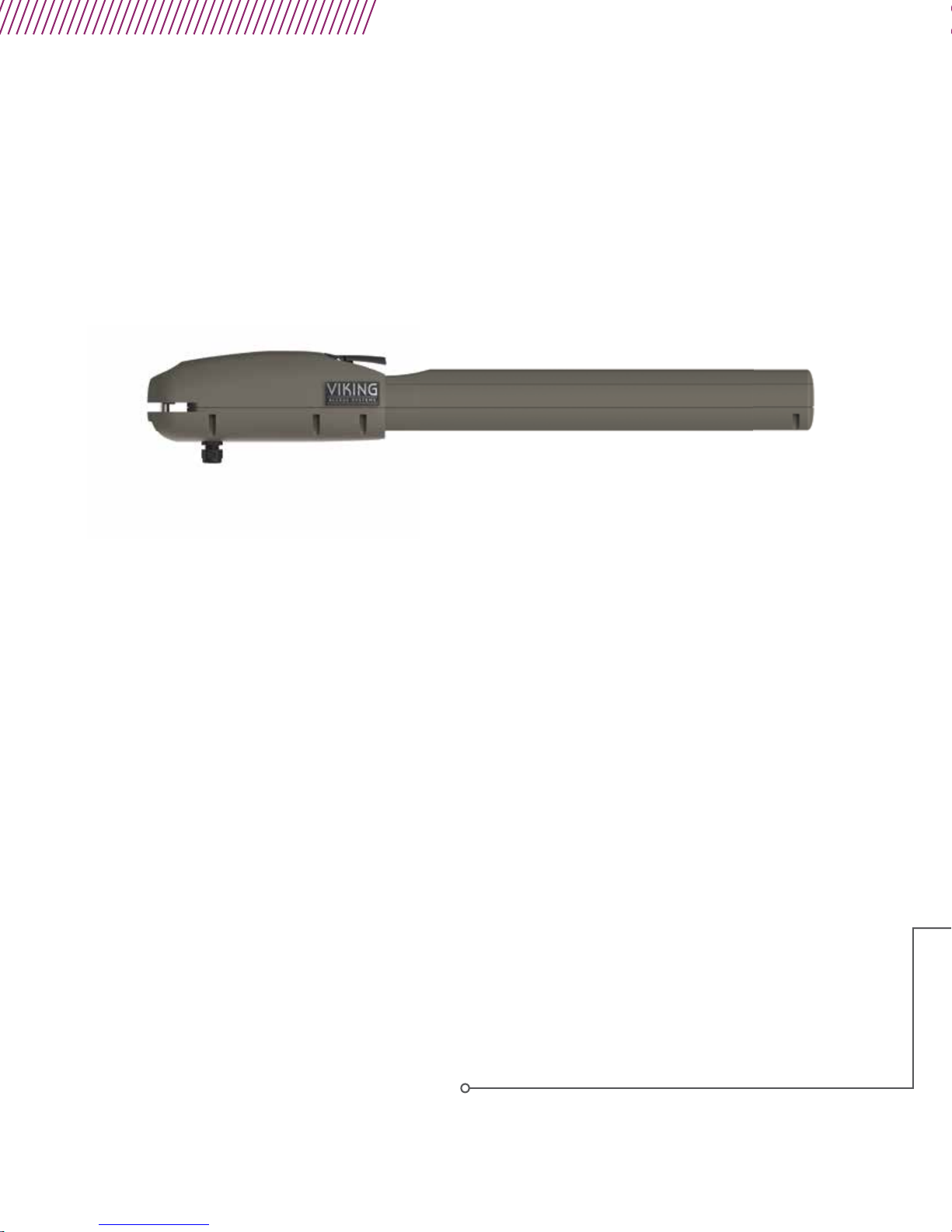
THE VIKING E-4™ SWING GATE OPERATOR
Page 3

E-4 Vehicular Swing Gate Operator • Revision E4MN10.A1 • September 2018
Page 4
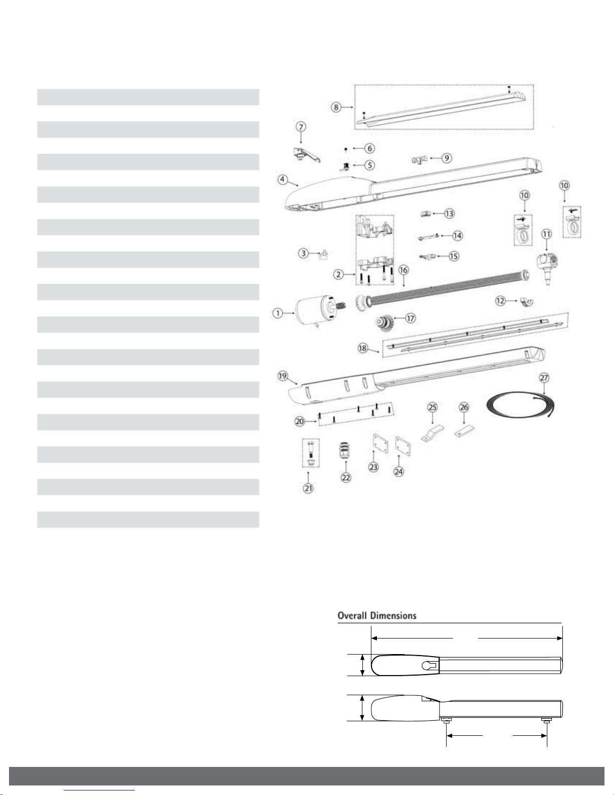
PARTS DIAGRAM - OPERATOR:
Item Description Part No.
1
Motor (24 VDC) E4MO
2
Gearbox Chassis
3 Grease Cup E4GGC
4 Casing Upper E4CU
5 Lock & Keys, Manual Release E4LMR
6 Key, Manual Release E4KEY
7 Handle, Manual Release E4HMR
8 Access Cover E4AC
Level Assembly
9
10 Limit Positive Stop E4LPS
11 Carrier Assembly E4CA
12 Bearing Cap E4BC
13 Cam, Manual Release E4CMR
14 Plate, Manual Release E4PMR
15 Switch, Manual Release E4SMR
16 Leadscrew Assembly E4LSA
17 Gear Drive Assembly E4GDA
18 Dust Brush Set (optional) E4DB
19 Casing Lower E4CL
20 Casing Mounting Bolts E4CMB
21 Mounting Hardware, Back E4MHB
22 Strain Relief E4SR
23 Bracket Mounting Plate 3X4” E4BMP3X4
24 Bracket Mounting Plate 4X6” E4BMP4X6
25 Mounting Bracket, Front E4MBF
26 Mounting Bracket, Back E4MBB
27 2 Conductor Cable VA-2CB16
E4GBC
E4LA
2
36.4”
3.9”
5.00”
19.50“
Max. Stroke
VIKING TECHNICAL SUPPORT 1.800.908.0884
Page 5
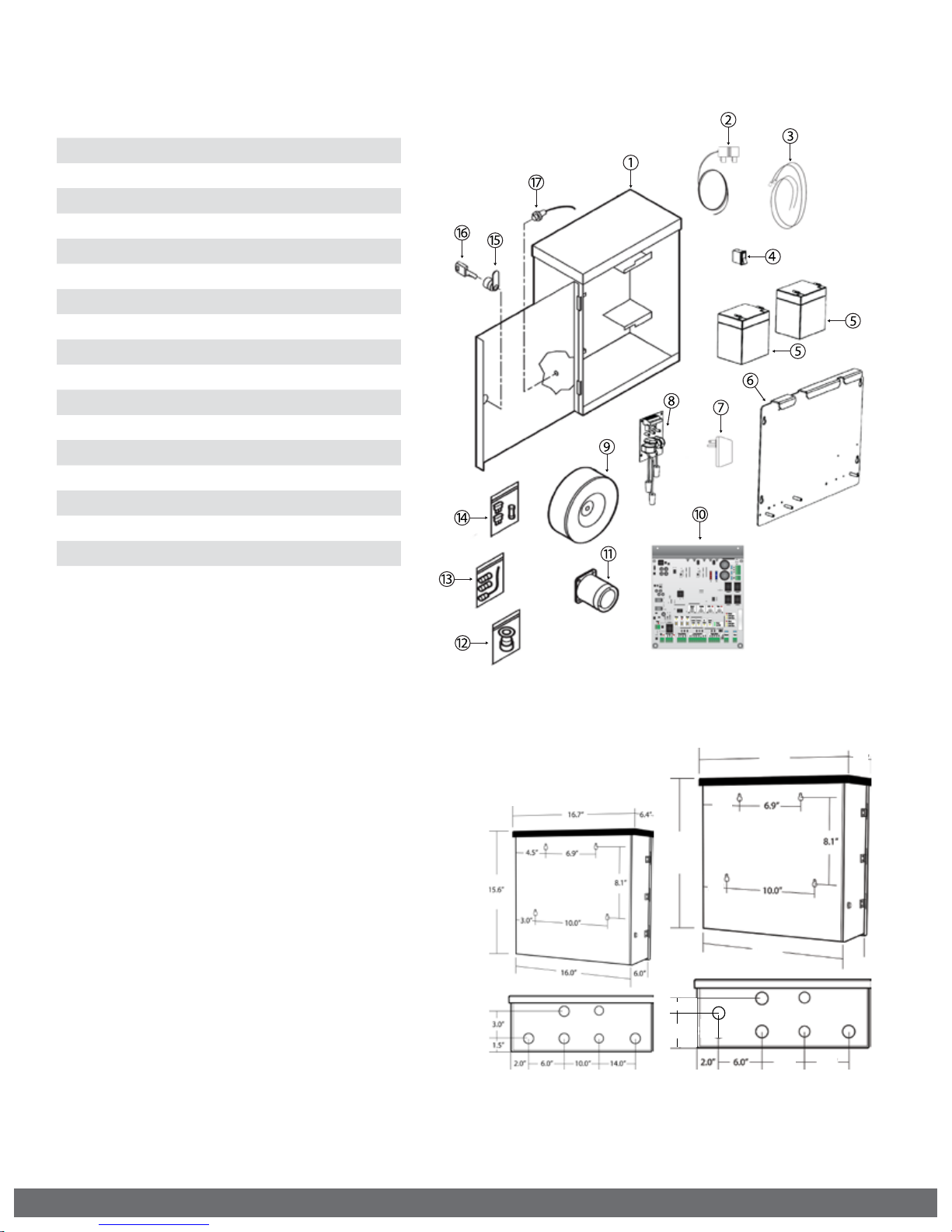
PARTS DIAGRAM - CONTROLLER:
Item Description Part No.
1
ECU Cabinet Chassis (Standard) VNXECUBB
2
Power Harness
3 Battery Harness E4BTH
4 Battery Switch DUMRS10
5 Battery DUBB12
6 Board Mounting Plate E4CBMP
7 Plug-in Transformer PT24V1A
8 EMI Board (optional) DUEMI10
Toroid Transformer - 10 amp (optional)
9
10 Control Board VE4PCB
11 Alarm DUAL10
12 Strain Relief (ECU) DH3/4NMCC
13 Radio Antenna Kit VARAK
14 Fuse Kit E4FSKT
15 Lock & Keys, Door ECUKEYC20
16 Key, Door ECUKEY20
17 Alarm Reset Switch ECURW
E4PH
DUTT10
VIKING TECHNICAL SUPPORT 1.800.908.0884
18.5”
18.1”
18.25 ”
5.5”
4.0”
12.0” 15.5”
Standard ECU *
*Standard ECU is depicted and related to parts list provided.
Large ECU
(OPTIONAL)
#VA-ECUBBB
8.5 ”
8”
3
Page 6
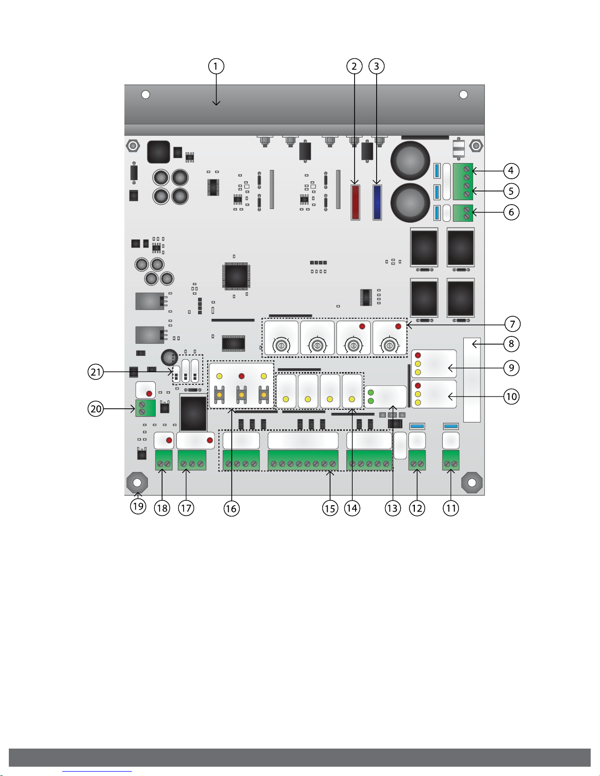
CONTROL BOARD REFERENCES:
AC
AC
AC
AC
+
+
Bat
Bat
-
-
DC IN
DC IN
+
+
-
-
4
4
15
15
4A
4A
15A
15A
Siren
Siren
+
+
Aux.
Aux.
Pwr
Pwr
+ -
+ -
1.
HEAT SINK - MASTER/SINGLE
secures the control board and dissipates heat.
2.
FUSE HOLDER - 4 AMP
for the charging circuit.
3.
FUSE HOLDER - 15 AMP
for the motor circuit.
4.
AC POWER CONNECTION
24VAC to the control board. pg 20
5.
BATTERY CONNECTION
24VDC charge voltage to the batteries.
6.
DC POWER CONNECTION
24VDC to the control board. pg 21
MS
Auto Open
Auto Open
Dual Gate
Sync
Sync
Magnetic Lock
Magnetic Lock
COM
COM
N.O. N.C.
N.O. N.C.
SpeedOverlap ODS
SpeedOverlap ODS
Normal
Normal
Max Min
Max Min
OpenStopClose
OpenStopClose
Center
Center
Loop
Loop
Guard Station
Guard Station
9.
Stop
Stop
Close
Close
GND
GND
MASTER MOTOR STATUS LEDs
Open
Open
Loop Connector
Loop Connector
Center
Center
GND
GND
GND
GND
indicates sMaster motor status. pg 34
10.
SLAVE MOTOR STATUS LEDs
indicates Slave motor status. pg 34
11.
SLAVE MOTOR CONNECTION
provides power to the Slave motor. pg 23
12.
MASTER or SINGLE MOTOR CONNECTION
provides power to the Master motor. pg 22
13.
POWER and BATTERY STATUS LEDs
indicates power supply status. pg 22
14.
INPUT STATUS LEDs
indicates input status. pg 35
3
3
60
60
ReOpen
ReOpen
Sens
Sens
ReOpen
ReOpen
GND
GND
UL
UL
UL
UL
Sens
Sens
GND
GND
100 0 60
100 060
Radio
Radio
Rec.
Rec.
+28V
+28V
Timer
Timer
Power
Power
Low Bat
Low Bat
Radio Station
Radio Station
GND GND
GND GND
+28V +28V
+28V +28V
Radio
Radio
Off
Off
Master
Master
Limit Open
Limit Open
Limit Close
Limit Close
Slave
17.
Slave
Limit Open
Limit Open
Limit Close
Limit Close
Master
Master
Slave
Slave
Supply +28V
Supply +28V
Class 2
Class 2
“MAGNETIC LOCK Relay” and Status LED
status of this on-board relay. pg 31, 35
18.
“AUX. PWR” Terminal Block
used for solar applications & in-motion
warning devices. pg 21
19.
CONTROL BOARD MOUNTING HOLES
secures and grounds the control board.
20.
“Siren” Terminal Block
Vikings UL Siren is connected here. pg 12, 26
21.
FEATURE ACTIVATION PIN HEADERS
activate features by placing a jumper onto the
pin headers. pg 25
7.
FEATURE ACTIVATION TRIM POTS
activate and set features. pg 24
8.
SERIAL NUMBER
control board serial number for identification
4
15.
ACCESS CONTROL TERMINAL BLOCKS
accessory connections. pg 27-29, 37-39
16.
ON-BOARD 3 BUTTON STATION
controls the gate during setup and testing
VIKING TECHNICAL SUPPORT 1.800.908.0884
Page 7

TABLE OF CONTENTS:
42
37-40
PARTS DIAGRAM/PARTS LIST 2
OPERATOR REFERENCES 3
CONTROL BOARD REFERENCES 4
IMPORTANT SAFETY INFORMATION 6-12
Important Safety Instructions 6
Important Installation Instructions 7
Maintenance 8
General Safety Precautions 8-9
Operator Classification 9
Secondary Entrapment Protection Requirements 10
Secondary Entrapment Protection Installation 11
Manual Release 11
Audible Alarm Reset Installation 12
Warning Placard Installation 12
IMPORTANT INSTALLATION INFORMATION 13
Specifications 13
GATE OPERATOR INSTALLATION 14-18
Pull to Open Installation 14
Push to Open Installation 15
Mounting the Gate Operator 16
Post Mounting Option 17
Limit Switch Setup 18
ECU BOX INSTALLATION 19
ELECTRICAL INSTALLATION 20-23
High Voltage Supply Option 20
Low Voltage Supply Option 21
Solar Supply Option 21
Motor Cable 22-23
CONTROL BOARD SETUP 24-26
Initial Settings 24-25
Obstruction Detection Sensor (ODS) 26
ACCESSORY CONNECTIONS 27-32
Radio Receiver (Typical) 27
Open Commands, Guard Station 28
Viking Loop Rack 29
Guidelines for Loop Installations 30
Magnetic Lock, Lock Solenoid 31
Barrier Arm Synchronization 32
TROUBLESHOOTING 34-36
LED References 34-35
Solutions 36
APPENDIX A & B 37-40
VIKING EXPANSION PRODUCTS 42
VIKING TECHNICAL SUPPORT 1.800.908.0884
5
Page 8

IMPORTANT SAFETY INFORMATION
! WARNING! Not Following these instructions may cause severe injury or death.
IMPORTANT SAFETY INSTRUCTIONS
! WARNING! To reduce the risk of severe injury or death.
1.
READ AND FOLLOW ALL INSTRUCTIONS.
2.
Never let children operate or play with gate controls. Keep the remote away from
children.
3.
Always keep people and objects away from the gate. NO ONE SHOULD CROSS THE
PATH OF THE MOVING GATE.
4.
Test the gate operator monthly. The gate MUST reverse on contact with a rigid object or
when an object activates the non-contact sensors. After adjusting the force or the limit
travel, retest the gate operator. Failure to adjust and retest the gate operator properly
can increase the risk of injury or death.
5.
Use the emergency release only when the gate is not moving.
6.
KEEP GATES PROPERLY MAINTAINED. Read the user’s manual. Have a qualified service
person make repairs to gate hardware.
7.
The entrance is for vehicles only. Pedestrians must use a separate entrance.
8.
Every gate operator installation MUST have secondary protection devices against
entrapment, such as edge sensors and photo beams more in particularly in places
where the risk of entrapment is more likely to occur.
9.
SAVE THESE INSTRUCTIONS.
IMPORTANT INSTALLATION INSTRUCTIONS
1.
Install the gate operator only when:
a.
The operator is appropriate for the construction of the gate and usage Class of the
gate (refer to page 9),
b.
All openings of a horizontal slide gate are guarded or screened from the bottom of
the gate to a minimum of 6 feet (1.83 m) above the ground to prevent a 2-1/4 inch
(57.2 mm) diameter sphere from passing through the openings anywhere in the gate,
and in that portion of the adjacent fence that the gate covers in the open position,
c.
ALL EXPOSED PINCH POINTS ARE ELIMINATED OR GUARDED, AND
d.
GUARDING IS SUPPLIED FOR EXPOSED ROLLERS.
2.
The Operator is intended for installation only on gates used for vehicles. Pedestrians
must be supplied with a separate access opening. The pedestrian access opening
shall be designed to promote pedestrian usage. Locate the gate such that persons will
not come into contact with the vehicular gate during the entire path of travel of the
vehicular gate.
3.
The gate must be installed in a location so that enough clearance is supplied between
the gate and adjacent structures when opening and closing to reduce the risk of
entrapment. Swinging gates shall not open in to the public access areas.
4.
The gate must be properly installed and work freely in both directions prior to the
installation of the gate operator. Do not over-tighten the operator clutch or pressure
relief valve to compensate for a damaged gate.
5.
The gate operator controls must be placed so that the user has full view of the gate area
when the gate is moving AND AWAY FROM THE GATE PATH PERIMETER.
6.
Controls intended for user activation must be located at least six feet (6’) away from
any moving part of the gate and where the user is prevented from reaching over, under,
around or through the gate to operate the controls.
Exception: Emergency access controls only accessible by authorized personnel (i.e. fire,
police, EMS) may be placed at any location in the line-of-sight of the gate.
6
VIKING TECHNICAL SUPPORT 1.800.908.0884
Page 9

IMPORTANT SAFETY INFORMATION
! WARNING! Not Following these instructions may cause severe injury or death.
IMPORTANT INSTALLATION INSTRUCTIONS (Continued)
7. The Stop and/or Reset button must be located in the line-of-sight of the gate. Activation
of the reset control shall not cause the operator to start.
8. A minimum of two (2) WARNING SIGNS shall be installed, in the area of the gate. Each
placard is to be visible by persons located on the side of the gate on which the placard is
installed.
9. For gate operators using non-contact sensors (photoelectric beam or like) in
accordance with section 31.1.1 of the UL standard:
a. See instructions on the placement of non-contact sensors for each type of
application (refer to page 10).
b. Care shall be exercised to reduce the risk of nuisance tripping, such as when a
vehicle, trips the sensor while the gate is still moving, and
c. One or more non-contact sensors shall be located where the risk of entrapment or
obstruction exists, such as the perimeter reachable by a moving gate or barrier (refer
to page 10).
d. Use only - Omron: E3K-R10K4-NR-1 // EMX: IRB-RET, IRB-MON // Miller Edge: RG-
K-R, PG-K-R100, PG-K-R50, MIM-62
10. For a gate operator utilizing a contact sensor (edge sensor or like) in accordance
with section 31.1.1 of the UL 325 standard:
a. One or more contact sensors shall be located where the risk of entrapment or
obstruction exists, such as a the leading edge, trailing edge, and post mounted both
inside and outside of a vehicular horizontal slide gate (refer to page 10).
b. One or more contact sensors shall be located at the bottom of a vehicular vertical lift
gate.
c. One or more contact sensors shall be located at the pinch point of a vehicular
vertical pivot gate.
d. A hardwired contact sensor shall be located and its wiring arranged so that
the communication between the sensor and the gate operator is not subject to
mechanical damage.
e. A wireless contact sensor such as one that transmits radio frequency (RF) signals
to the gate operator for entrapment protection functions shall be located where the
transmission of the signals are not obstructed or impeded by building structures,
natural landscaping or similar obstructions. A wireless contact sensor shall function
under the intended end-use conditions.
f. One or more contact sensors shall be located on the inside and outside leading edge
of a swing gate. Additionally, if the bottom edge of a swing gate is greater than 4
inches (101.6mm) but less than 16 inches (406 mm) above the ground at any point in
its arc of travel, one or more contact sensors shall be located on the bottom edge.
g. One or more contact sensors shall be located at the bottom edge of a vertical barrier
(arm).
h. Use only - EMX: WEL-200K // Miller Edge: ME110 through ME117, ME120, ME123,
MG020, MGR20, MGS20, RB-G-K10, MIM-62 // ASO: 25.30, 25.45, 95.20
VIKING TECHNICAL SUPPORT 1.800.908.0884
7
Page 10

IMPORTANT SAFETY INFORMATION
! WARNING! Not Following these instructions may cause severe injury or death.
MAINTENANCE
Remove the Power Harness from the Control Board. (refer to page 20)
• Clean and lubricate the turning pins and gate hinges using the recommended
lubricant.
• Check that all mounting hardware of the gate operator is properly tighten.
• Ensure that the gate moves freely.
• Check for corroded parts and replace if necessary.
• Check the battery for the following:
- Battery connections must be free of corrosion.
- Battery voltage must be 26VDC (fully charged battery).
Reconnect the Power Harness for the Control Board. (refer to page 20)
• Check and confirm the proper operation of all safety devices (photoelectric
eye, edge sensors or like).
• Check and confirm the operation of all installed accessories.
• Check and confirm the operation of all special features such as the Intelligent
Obstruction Sensor and Hold Open Timer. (refer to pages 25-27)
• Check and confirm the operation of the manual release. (refer to page 11)
• Verify the functionally of the battery backup, or power failure option, by
turning off the main power source (115VAC or 230VAC). DO NOT FORGET TO
TURN ON THE MAIN POWER SOURCE AFTER VERIFICATION.
GENERAL SAFETY PRECAUTIONS
The following precautions are an integral and essential part of the product and must be
supplied to the user. Read them carefully as they contain important indications for the
safe installation, use and maintenance.
• These instruction must be kept and forwarded to all possible future users of the
system.
• This product must be used only for that which it has been expressly designed.
• Any other use is to be considered improper and therefore dangerous.
• The manufacturer cannot be held responsible for possible damage caused by
improper, erroneous or unreasonable use.
• Avoid operating in the proximity of the hinges or moving mechanical parts.
• Do not enter the path of the moving gate while in motion.
• Do not obstruct the motion of the gate as this may cause a situation of danger.
• Do not allow children to play or stay within the path of the moving gate.
• Keep remote control or any other control devices out of the reach of children, in
order to avoid possible involuntary activation of the gate operator.
• In case of break down or malfunctioning of the product, disconnect from the main
power source. Do not attempt to repair or intervene directly, contact only qualified
personnel for repair.
• Failure to comply with the above may create a situation of danger.
• All cleaning, maintenance or repair work must be carried out by qualified personnel.
• In order to guarantee that the system works efficiently and correctly it is important
to have the manufacturer’s instructions on maintenance of the gate and operator
carried out by qualified personnel.
• In particular, regular checks are recommended in order to verify that the safety
devices are operating correctly.
All installation, maintenance and repair work must be documented and made
available to the user.
8
VIKING TECHNICAL SUPPORT 1.800.908.0884
Page 11
IMPORTANT SAFETY INFORMATION
! CAUTION: To Reduce the Risk of Fire or Injury to Persons:
a.
Use only the following type and size battery(ies): Yuasa NP7-12 or VIKING DUBA12
b.
Do not dispose of the battery(ies) in re. The cells may explode. Check with local
codes for possible disposal instructions.
c.
Do not open or mutilate the battery(ies). Released electrolyte is corrosive and may
cause damage to the eyes or skin. It may be toxic if swallowed.
d.
Exercise care in handling batteries in order not to short the battery with conducting
materials such as rings, bracelets and keys.
e.
Change the battery(ies) provided with or identied for use with this product only in
accordance with the instructions and limitations specied in this manual.
f.
Observe proper polarity orientation between the battery(ies) and charging circuit.
g.
Do not mix batteries of different sizes or from different manufactures in this product
(applies to products employing more than one user replaceable secondary battery).
h.
A battery-operated product employing a secondary battery supply intended to be
charged within the product shall contain specic instructions concerning the proper
method of charging.
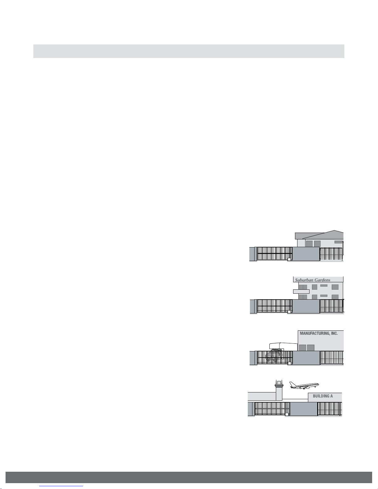
UL325 Gate Operator Classifications
GLOSSARY
RESIDENTIAL VEHICULAR GATE OPERATOR
CLASS I -
for use in garages or parking areas associated with a
residence of one-to four single families.
COMMERCIAL/GENERAL ACCESS VEHICULAR GATE OPERATOR
CLASS II –
intended for use in a commercial location or building
such as a multi-family housing unit (five or more single
family units), hotel, garages, retail store, or other
building servicing the general public.
INDUSTRIAL/LIMITED ACCESS VEHICULAR GATE OPERATOR
CLASS III –
intended for use in an industrial location or building
such as a factory or loading dock area or other
locations not accessible by or intended to service the
general public.
RESTRICTED ACCESS VEHICULAR GATE OPERATOR
CLASS IV –
intended for use in a guarded industrial location or
building such as an airport security area or other
restricted access locations not servicing the general
public, in which unauthorized access is prevented via
supervision by security personnel.
A vehicular gate operator (or system) intended
A vehicular gate operator (or system)
A vehicular gate operator (or system)
A vehicular gate operator (or system)
Install the gate operator only when:
The operator is appropriate for the construction of the gate and the Usage Class of
the gate.
VIKING TECHNICAL SUPPORT 1.800.908.0884
9
Page 12

IMPORTANT SAFETY INFORMATION
! WARNING! Not Following these instructions may cause severe injury or death.
Monitored Entrapment Protection Requirements
IMPORTANT: MONITORED PROTECTION MUST BE INSTALLED
•
REQUIRED BY UL 325, an approved MONITORED entrapment protection sensor is
REQUIRED to be installed in all areas accessible to potential entrapment and pinch
points.
•
For a horizontal swing gate operator, at least one Monitored External Entrapment Sensor is
required in each direction of travel. Except, if there is no entrapment zone in one direction
of travel, it is not required to have a Monitored Entrapment sensor for that direction of
travel.
! If there is a possible entrapment zone in the open direction, an external sensor MUST be
connected to the “UL” input or the installation will not comply with UL 325.
! An external sensor connected to the “ReOpen” input terminal will protect against
entrapment ONLY in the closing direction.
•
The installed sensor MUST be “10K Resistor Based”.
•
You may connect up to FOUR monitored sensors, wired in parallel, to either the “UL” and/or
“ReOpen” terminals, for a total of 8 monitored sensors.
•
Failure to install the required monitored entrapment protection sensor(s) may render the
gate operator INOPERABLE. The gate can be moved manually. Refer to page 11.
•
Consult the installation manual of the sensor for detailed information about the usage,
installation and maintenance.
•
Use only UL Recognized Component Edge Sensors and Photoelectric Sensors. Refer to pg 7.
SWING GATE ENTRAPMENT ZONE – Locations between a moving gate or moving, exposed
operator components and a counter opposing edge or surface where entrapment is possible
up to 1.8 m (6 ft) above grade. Such locations occur if during any point in travel:
a.
The gap between the bottom of a moving gate and the ground is greater than 101.6 mm
(4 in) and less than 406 mm (16 in); or
b.
The distance between the center line of the pivot and the end of the wall, pillar, or
column to which it is mounted when in the open or closed position exceeds 101.6 mm (4
in). Any other gap between a moving gate and fixed counter opposing edges or surfaces
or other fixed objects is less than 406 mm (16 in) (examples are walls, curbs, berms or
other immovable objects).
Photoelectric Sensor (non-contact sensor)
Edge Sensor (contact sensor)
10
VIKING TECHNICAL SUPPORT 1.800.908.0884
Page 13
Loop Connector
GND
Center
GND
ReOpen
GND
UL
GND
+28V
Loop Connector
GND
Center
GND
ReOpen
GND
UL
GND
+28V
IMPORTANT SAFETY INFORMATION
! WARNING! Not Following these instructions may cause severe injury or death.
! Cable use in Class 2 circuit to an external device shall be type CL2, CL2P, CL2R, CL2X or other
cable with equivalent or better electrical, mechanical, and ammability ratings.
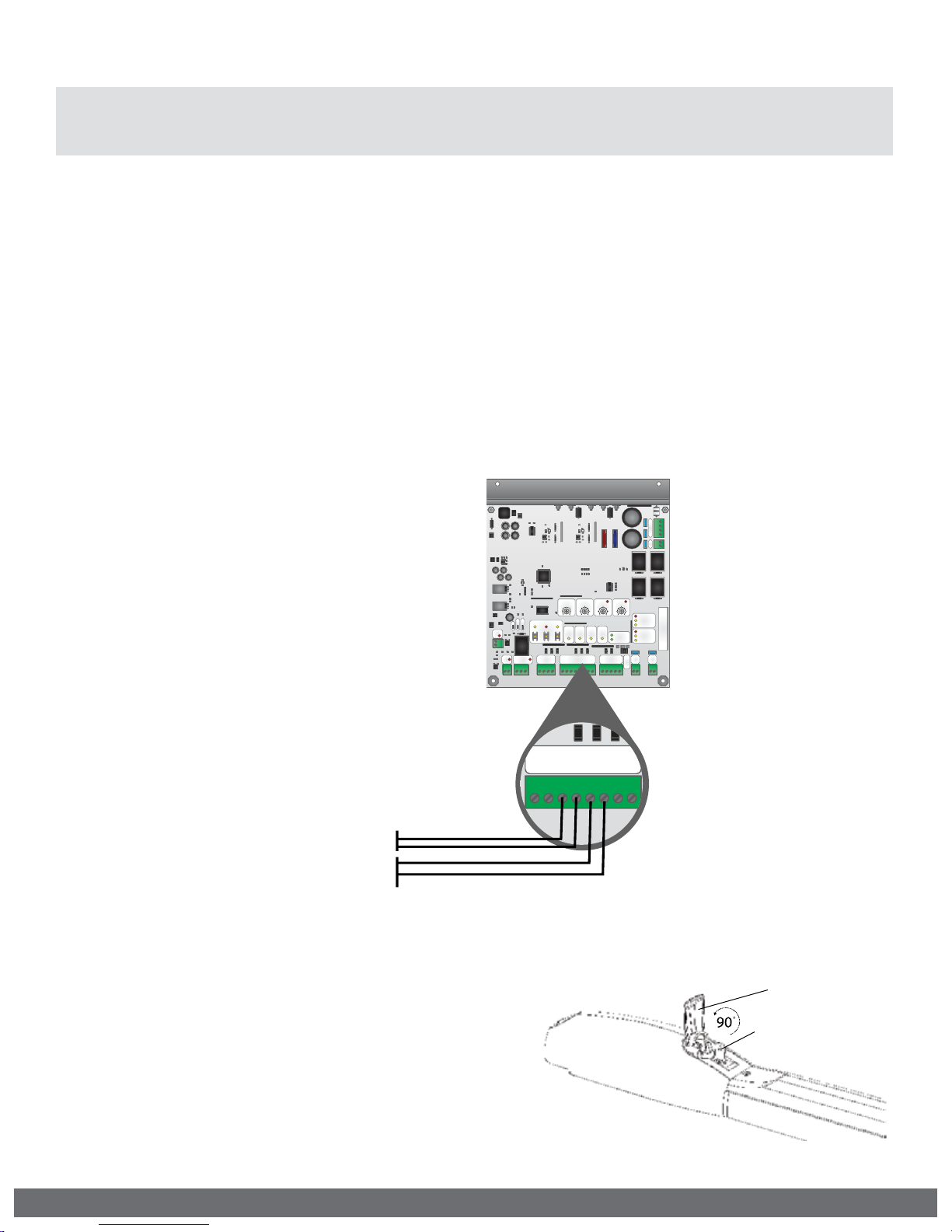
Monitored Entrapment Protection Installation
!
IMPORTANT: A minimum of one Monitored External Entrapment Sensor is required to be
connected to the UL terminal OR the ReOpen terminal. If there is a possible entrapment
zone in the open direction, an external sensor MUST be wired to the “UL” input or the
installation will not comply with UL 325.
“UL” Protects against entrapment in both the opening and closing directions. Input will
either stop the gate or reverse the gate approximately 12” in the opposite direction it was
traveling.
“ReOpen” Protects against entrapment in the closing direction ONLY. Input will reverse the
gate all the way to the Open Limit.
STEP 1
AC
AC
Remove the Power Harness from the Control
Board.
STEP 2
Connect the monitored entrapment protection
sensor(s) to the Viking control board as
illustrated below.
STEP 3
Learn the number of sensors connected:
•
Press and hold the Stop Button.
•
Connect the Power Harness to the Board.
•
Release the Stop Button after 10 seconds when
the “Center Loop” and “Radio Rec.” LEDs begin
to flash.
10K (Sensor’s Monitored Terminals)
4
4
4A
4A
Speed Overlap ODS
Speed Overlap ODS
Normal
Normal
Max Min
Max Min
603100 0 60
Guard Station
Guard Station
Close
Close
GND
GND
603100 060
OpenStopClose
OpenStopClose
Radio
UL
Radio
UL
ReOpen
Center
ReOpen
Center
Rec.
Rec.
Loop
Loop
Sens
Sens
Sens
Sens
Radio Station
GND
GND
Loop Connector
Loop Connector
Center
Center
GND
GND
Radio Station
GND
GND
GND GND
GND
GND
GND GND
+28V
+28V
ReOpen
ReOpen
UL
UL
Stop
Stop
Open
Open
MS
Auto Open
Auto Open Dual Gate
Sync
Sync
Siren
Siren
+
+
Aux.
Aux.
Magnetic Lock
Magnetic Lock
Pwr
Pwr
+ -
+ -
COM
COM
N.O. N.C.
N.O. N.C.
AC
AC
NOTE: The “Stop” LED
+
+
Bat
Bat
-
-
15
15
+
+
DC IN
DC IN
-
-
15A
15A
will be flashing if there
is a failure with at
least one monitored
Timer
Timer
Off
Off
Power
Power
Low Bat
Low Bat
Master
Master
+28V +28V
+28V +28V
Radio
Radio
Supply +28V
Supply +28V
Class 2
Class 2
entrapment sensor
Master
Master
Limit Open
Limit Open
Limit Close
Limit Close
and the gate operator
Slave
Slave
Limit Open
Limit Open
Limit Close
Limit Close
will be rendered
Slave
Slave
inoperable.
10K (Sensor’s Monitored Terminals)
Manual Release
When manual operation is required:
1.
Lift the Release Handle.
2.
Insert the Release Key and rotate Key to
unlock the Handle .
3.
Rotate Handle counter clockwise.
The gate can now be moved manually.
VIKING TECHNICAL SUPPORT 1.800.908.0884
Release Handle
Release Key
11
Page 14
N
C
p
N
C
p
IMPORTANT SAFETY INFORMATION
! WARNING! Not Following these instructions may cause severe injury or death.
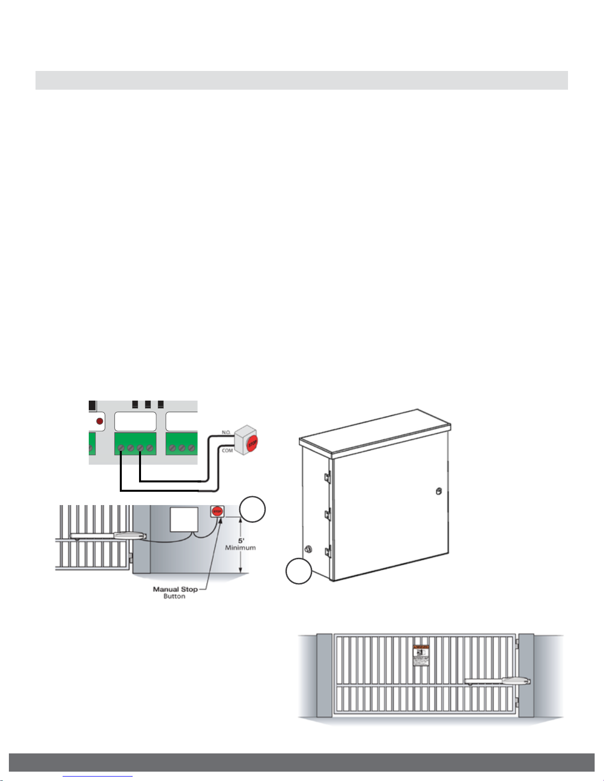
Audible Alarm Reset Switch Installation
Manual Reset for the Audible Alarm
•
UL325 standard requires an audible alarm to sound after two consecutive events
detected by the primary entrapment protection of the gate operator (obstruction
sensor).
•
The audible alarm will continue to sound for 5 minutes or until a stop command gets
actuated.
•
The Stop command can be actuated in three different forms:
1.
Using the Built in Stop switch on the Control Board; or
2.
Using an External Stop button within the sight of the gate, away from moving parts of
the gate and out of reach of children.
a.
Controls intended for user activation must be located at least six feet (6’) away
from any moving part of the gate and where the user is prevented from reaching
over, under, around, or through the gate to operate the controls. Outdoor or easily
accessible controls shall have a security feature to prevent unauthorized use.
b.
The Stop and/or Reset button must be located in the line-of-sight of the gate.
Activation of the reset control shall not cause the operator to start.
3.
Using the Reset Button on the Electronic Control Unit that is externally accessible on
the left side of the cabinet.
ock
ock
.
.
.
.
Guard Station
Guard Station
Stop
Stop
Close
Close
GND
GND
Open
Open
Loo
Loo
Center
Center
GND
GND
GND
GND
2
3
Warning Placard Installation
•
All Warning Placards must be installed
where visible in the area of the gate.
•
A minimum of two placards shall be
installed.
•
A placard is to be installed in the area of
each side of the gate and be visible.
12
VIKING TECHNICAL SUPPORT 1.800.908.0884
Page 15
IMPORTANT INSTALLATION INFORMATION
! CAUTION: To Reduce the Risk of Fire or Injury to Persons:
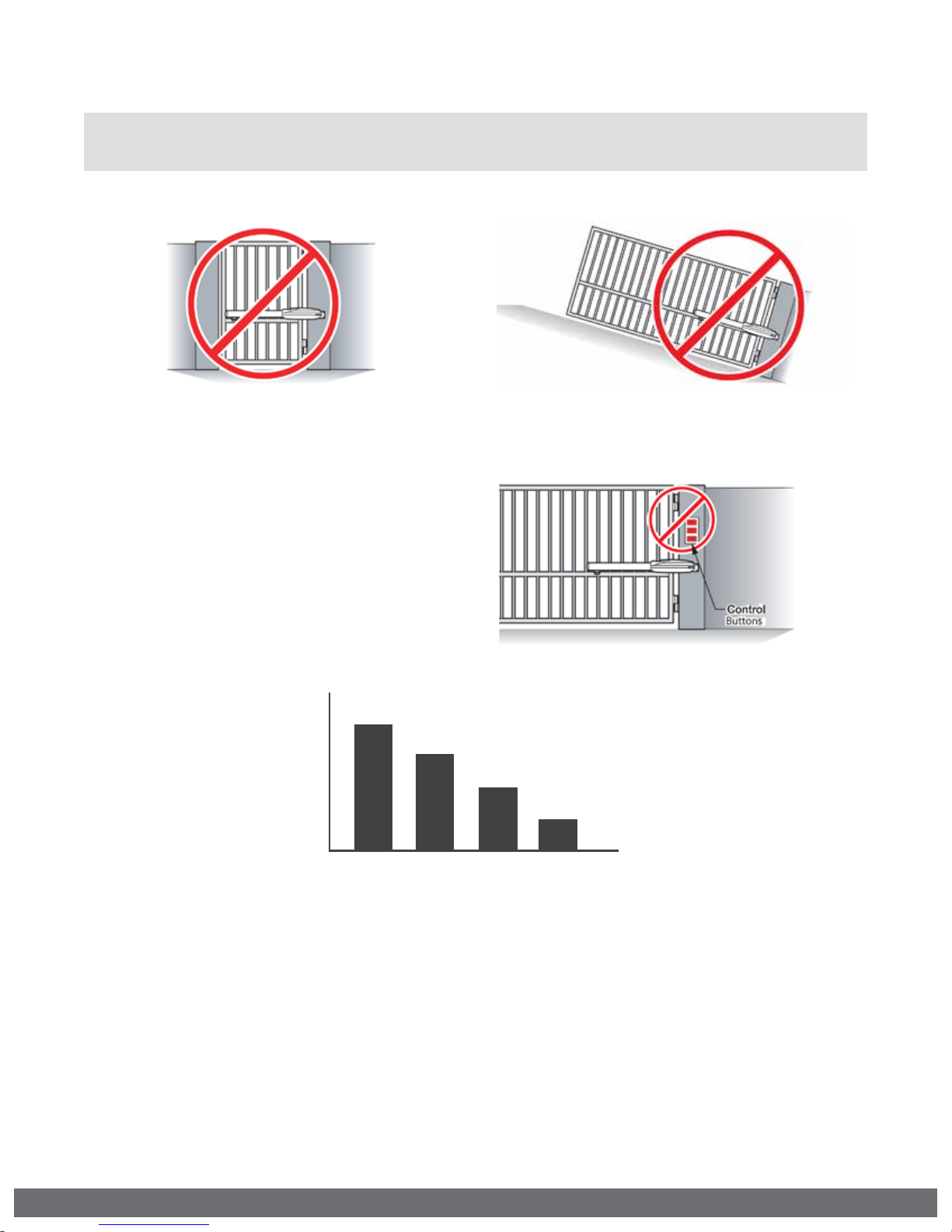
! WARNING: For use with gates at a maximum 850 lbs. in weight or 16 ft. in length.
DO NOT allow pedestrian use of this gate DO NOT install the gate operator to lift gates
Locate Control Buttons:
1.
Within sight of the gate,
2.
At a minimum height of 5 feet
so small children are not able to
reach it; and
3.
At least 6 feet away from all
moving parts of the gate.
LB
850 lb
75 0 lb
650 lb
550 lb
850 lb
750 lb
10’1 2’ 14’1 6’
10’ 12’ 14’ 16’
Gate Weight/Length Relationship
Specications:
UL 325 Classifcation: Class I
650 lb
550 lb
FT
*Refer to page 9
Power Requirements: 115VAC / 230VAC (1.5* Amp / 1.0* Amp)
Single Phase (50Hz / 60Hz)
Alternative Power: 24V AC / DC (min. 20VA) or Solar
Operating Temperature: -20°F (-28°C) to 160°F (71°C)
Maximum Weight: 850 lbs.
Maximum Length: 16 ft.
VIKING TECHNICAL SUPPORT 1.800.908.0884
*Each Gate Operator
13
Page 16

GATE OPERATOR INSTALLATION
Pull to Open Installation Option
This application is typically used to open the gate towards the inside of the property.
The operator will “PULL” the gate to open.
1.
The gate must be installed in a location so that enough clearance is provided
between the gate and adjacent structures to reduce the risk of entrapment when
opening and closing.
2.
Swing gates are not to open into public access areas.
ALL DIMENSIONS ARE MEASURED IN INCHES
NOTE: Back Mounting Bracket
must be cut to obtain correct
dimension “A” provided below.
Range A B C D E
90° - 120° 8.000 4.500 24.000 28.590 4.750
121° - 135° 4.750 7.750 24.000 31.770 4.750
! Varying from the dimensions provided above may severely affect the speed and
14
performance of the gate operator.
VIKING TECHNICAL SUPPORT 1.800.908.0884
Page 17

GATE OPERATOR INSTALLATION
Push to Open Installation Option
This application is typically used to open the gate towards the outside of the property.
The operator will “PUSH” the gate open.
1.
The gate must be installed in a location so that enough clearance is provided between
the gate and adjacent structures to reduce the risk of entrapment when opening and
closing.
2.
Swing gates are not to open into public access areas.
! Varying from the dimensions provided above may severely affect the speed and
VIKING TECHNICAL SUPPORT 1.800.908.0884
performance of the gate operator.
15
Page 18

GATE OPERATOR INSTALLATION
! Caution: If the Front Mounting Bracket is not attached to a frame member that
runs the full length of the gate, the gate operator may damage the gate. DO NOT
attach the bracket or backing plate to just a few pickets.
Mounting the Gate Operator
Refer to Dimensions
A & B for positioning
Level Line
STEP 1
Front Mounting Bracket:
a.
Position the bracket according to the
dimensions provided on pages 14 or 15.
b.
Ensure the bracket is level and tack
weld in place.
! TIP: Alternatively, if you choose to bolt
this bracket to the gate, a backing plate
has been provided with four bolt holes.
STEP 3
Mount the Gate Operator:
a.
Install the operator onto the mounting
brackets.
b.
Manually Release the E-4 Operator.
Refer to page 11.
c.
Manually move the gate to ensure the
gate and operator moves freely.
STEP 2
Back Mounting Bracket:
a.
Cut and position the bracket according
to pages 14 or 15.
b.
Ensure the bracket is level and tack
weld in place.
! TIP: Alternatively, if you choose to bolt
this bracket to the gate, a backing plate
has been provided with four bolt holes.
STEP 4
Complete the Installation:
a.
Dismount the operator.
b.
Complete the welding process.
c.
Lubricate the front bracket pivot point.
d.
Reinstall the gate operator and verify
once again that the gate moves freely.
e.
Rotate the Manual Release Handle
clockwise to the engage position.
16
VIKING TECHNICAL SUPPORT 1.800.908.0884
Page 19

3-1/ 2” Pipe (4 .00” O.D.)
GATE OPERATOR INSTALLATION
Post Mounting Option
A Post Mount Kit is available for the E-4 Operator as an option to welding the operator
Mounting Brackets to the gate and column. Part # VA-E4PSKT
1.
Mounting hardware provided for 3 1/2” round, 4” and 6” square posts.
2.
Mounting Brackets are powder coated 1/4” steel.
4” Square Pipe
Open Left
4” Square Pipe
Open Right
3-1/2” Round
Pipe
Open Left
3-1/2” Round
Pipe
Open Left
Grade Level
Consult Local Building Codes
4” Squa re Pipe
6” Squa re
6” Square Pipe
Open Left/Right
VIKING TECHNICAL SUPPORT 1.800.908.0884
17
Page 20

GATE OPERATOR INSTALLATION
Limit Position Setup
! IMPORTANT: The gate operator uses positive stops to set the limits.
STEP 1
Manually Release the E-4 Operator:
a. Lift the Release Handle.
b. Insert the Release Key.
c. Rotate Release Key.
d. Rotate Handle.
STEP 3
Set the Limit Positions:
a.
Manually position the gate to the desired
Close Limit Position.
b.
Loosen the setscrews for the Close Positive
Stop and slide the Stop up against the Lead
Screw Carrier.
c.
Re-secure the Close Positive Stop when the
proper position has been determined. Ensure
it is tightly secured.
d.
Repeat the above steps for the Open Limit
Position.
STEP 2
Remove the Lead Screw Cover:
a.
Remove the cover mounting screw.
b.
Remove the Lead Screw Cover.
STEP 4
Verify the set Limit Positions:
a. Re-engage the manual release.
b. Run the operator two full cycles to
verify that the limits are set at the desired
positions.
! TECHNICAL TIP: The Limit LEDs will illuminate solid when the limit position is set and the
operator is at the corresponding limit.
18
VIKING TECHNICAL SUPPORT 1.800.908.0884
Page 21

ECU BOX INSTALLATION
! WARNING: If the control box is not mounted properly it may fall, causing damage and/or
injury. The Electronic Control Unit (ECU) weight is approximately 40 lbs. Be sure that the
substrate being mounted to and the fasteners being used are appropriate to support the
weight of the control box.
Mounting the ECU Box
STEP 1
Disconnect all Wire
Harnesses from the
Control Board and
remove the Control
Board Mounting Plate.
The plate is held in the
box by four screws.
AC
AC
AC
AC
+
+
Bat
Bat
-
-
4
4
15
15
+
+
DC IN
DC IN
-
-
4A
4A
15A
15A
Timer
Timer
Speed OverlapODS
Speed OverlapODS
Normal
Normal
MaxMin
MaxMin
603100 0 60
603100 060
Off
Off
Master
Master
MS
OpenStopClose
OpenStopClose
Auto Open
Auto Open
Sync
Sync
Center
Center
Siren
Siren
Loop
Loop
+
+
Aux.
Aux.
Magnetic Lock
Magnetic Lock
Guard Station
Loop Connector
Guard Station
Loop Connector
Pwr
Pwr
+ -
+ -
Stop Open
Stop Open
COM
Close
Center
COM
Close
Center
GND
GND
GND
GND
N.O. N.C.
N.O. N.C.
Limit Open
Limit Open
Limit Close
Limit Close
Radio
UL
Radio
UL
ReOpen
ReOpen
Slave
Slave
Rec.
Rec.
Sens
Sens
Sens
Sens
Power
Power
Limit Open
Limit Open
Low Bat
Low Bat
Limit Close
Limit Close
Radio Station
Radio Station
Master
Master
Slave
Slave
GND
GND
GND
GND GND
GND
GND
GND
GND GND
+28V
+28V +28V
+28V
+28V +28V
ReOpen
ReOpen
UL
Radio
UL
Radio
Supply +28V
Supply +28V
Class 2
Class 2
STEP 2
Position the ECU Box
in the desired place
and mark the mounting
holes. Prepare the holes
to receive the anchors/
fasteners.
NOTE: Anchors are Not
Supplied.
STEP 3
Position the ECU Box
and secure it to the
mounting surface using
the Sealed Washers
provided (rubber side
of the washers against
the inside of the control
box).
VIKING TECHNICAL SUPPORT 1.800.908.0884
19
Page 22

ELECTRICAL INSTALLATION
AC
AC
+
-
+
-
Bat
DC IN
AC
AC
+
-
+
-
Bat
DC IN
! Caution: Always turn off power breakers when working with high voltage. DO NOT
connect the “Power Harness” to the Control Board until the electrical installation is
complete and ready for verification. To reduce the risk of electric shock, this equipment
(external plug-in transformer) has a grounding type Plug, that has a third (grounding) pin. This
plug will only t into a grounding type outlet. If the plug does not t into the outlet, contact a
qualied electrician to install the proper outlet. Do not change the plug in any way.
High Voltage Supply Option
STEP 1
!
WARNING: SINGLE PHASE AC ONLY
At the “EMI Board”:
a.
Set the “Voltage Selector” according
to the supply voltage (115V or 230V).
b.
Connect the incoming power wires
to the terminals as shown in the
illustration.
c.
Ground the ECU cabinet according to
local code or guidelines.
d.
Turn on the main facility breaker and
verify that all three (3) Status LEDs are
illuminated on the EMI Board.
1a
1b
Tips for proper ground installation:
To minimize the effects caused by lightning, follow
these guidelines:
•
Use a ground rod to provide a ground reference.
•
Consult your city code and be aware of
underground services in the site of the gate
operator to prevent inconveniences.
•
Always use a single bonding point for grounding.
•
All ground wires must be as short and as thick as
possible.
•
Prevent unnecessary turns or loops in all ground
wires.
STEP 2
At the Control Board:
a.
Reinstall the Control Board Mounting
Plate with the Control Board.
b.
Connect the outbound wires from the
Toroidal Transformer to the Green
and White “AC” wires of the “Power
Harness”. Polarity is not important.
Verify the “POWER” LED is illuminated
solid.
c.
Reconnect all other harnesses.
20
Ground Rod
4
4
15
15
4A
4A
15A
15A
Timer
SpeedOverlap ODS
SpeedOverlap ODS
Normal
Normal
Max Min
Max Min
603100 0 60
Stop
Stop
OpenStopClose
OpenStopClose
Open
Open
603100 060
ReOpen
Center
ReOpen
Center
Loop
Loop
Sens
Sens
Loop Connector
Loop Connector
Center
Center
GND
GND
GND
GND
ReOpen
ReOpen
GND
GND
UL
UL
MS
Auto Open
Auto Open
Sync
Sync
Siren
Siren
+
+
Aux.
Aux.
Magnetic Lock
Magnetic Lock
Guard Station
Guard Station
Pwr
Pwr
+ -
+ -
COM
Close
COM
Close
GND
GND
N.O. N.C.
N.O. N.C.
Timer
Off
Off
Radio
UL
Radio
UL
Rec.
Rec.
Sens
Sens
Power
Power
Low Bat
Low Bat
Radio Station
Radio Station
+28V
+28V
GND GND
GND GND
+28V +28V
+28V +28V
Radio
Radio
Supply +28V
Supply +28V
Class 2
Class 2
GND
GND
VIKING TECHNICAL SUPPORT 1.800.908.0884
Master
Master
Master
Master
Limit Open
Limit Open
Limit Close
Limit Close
Slave
Slave
Limit Open
Limit Open
Limit Close
Limit Close
AC
AC
AC
AC
+
+
Bat
Bat
-
-
2b
+
+
DC IN
DC IN
-
-
Slave
Slave
Page 23

ELECTRICAL INSTALLATION
Low Voltage Supply Option
As an alternative, the Control Board can be powered directly with 24VAC or 24VDC. The ECU
may be equipped with a 24VAC plug-in transformer as the power supply.
! Caution: The DC Power Supply Input at the Control board is Polarity Sensitive. If
supplying 24VDC directly to the Control Board, ensure correct DC polarity before
you apply this power supply to the Control Board.
! Caution: Always turn off power breakers when working with high voltage. DO NOT
connect the “Power Harness” to the Control Board until the electrical installation is
complete and ready for verification. To reduce the risk of electric shock, this equipment
(external plug-in transformer) has a grounding type Plug, that has a third (grounding) pin. This
plug will only t into a grounding type outlet. If the plug does not t into the outlet, contact a
qualied electrician to install the proper outlet. Do not change the plug in any way.
Plug the Plug-in Transformer into the nearest 115V receptacle and connect the outbound wires
from the Plug-in Transformer to the Green and White “AC” wires of the “Power Harness”.
Polarity is not important. Verify the “POWER” LED is illuminated solid.. Follow local codes or
guidelines.
24v AC 115v or 230v24v AC
Solar Supply Option
! IMPORTANT: The number of cycles achieved daily is dependent on many factors, including
local solar radiation data and power consumption of the motor and accessories. It is very
important that you consider this when using solar power.
VIKING TECHNICAL SUPPORT 1.800.908.0884
21
Page 24

Class 2
Supply +28V
Master
Class 2
Supply +28V
Master
ELECTRICAL INSTALLATION
Motor Cable - Master (Single)
NOTE:
The position of the motor wires will dictate in which direction the motor will travel
when given an open or close command.
STEP 3
Master Motor:
a.
Connect motor wires to the
“Master” Terminal Block, according
to the opening direction as
described below.
b.
Attach the grounding wire, non
insulated, to the Board Mounting
Plate using the screw provided.
Siren
Siren
+
+
AC
AC
AC
AC
+
+
Bat
Bat
-
4
4
15
15
4A
4A
15A
15A
Timer
Radio
Radio
Rec.
Rec.
Timer
Power
Power
Low Bat
Low Bat
Off
Off
Speed Overlap ODS
Speed Overlap ODS
Normal
Normal
Max Min
MS
Auto Open
Auto Open
Sync
Sync
Max Min
OpenStopClose
OpenStopClose
Center
Center
Loop
Loop
3
3
60
100 0 60
60
100 060
UL
UL
ReOpen
ReOpen
Sens
Sens
Sens
Sens
-
+
+
DC IN
DC IN
-
-
Master
Master
Limit Open
Limit Open
Limit Close
Limit Close
Slave
Slave
Limit Open
Limit Open
Limit Close
Limit Close
3a
Motor Wires Polarity
Master Pull or Push to Open:
Connect the motor wires to the “Master”
Terminal Block according to the opening
direction.
PUSH OPEN
RED BLACK
PULL OPEN
BLACK RED
Aux.
Aux.
Pwr
Pwr
+ -
+ -
Magnetic Lock
Magnetic Lock
COM
COM
N.O. N.C.
N.O. N.C.
Guard Station
Guard Station
GND
GND
OPEN LEFT
OPEN RIGHT
Close
Close
Open
Stop
Stop
Open
Open
Open
Loop Connector
Loop Connector
Center
Center
GND
GND
GND
GND
ReOpen
ReOpen
GND
GND
UL
UL
Master
RED
Outside
Inside
Master
BLACK
RED
GND
GND
BLACK
BLACK
Slave
+28V
+28V
Slave
RED
BLACK
RED
Radio Station
Radio Station
GND GND
GND GND
+28V +28V
+28V +28V
Radio
Radio
OPEN LEFT
OPEN RIGHT
Class 2
Class 2
Open
Master
Master
Supply +28V
Supply +28V
Open
Slave
Slave
3b
22
VIKING TECHNICAL SUPPORT 1.800.908.0884
Page 25

Motor Cable - Master (Dual)
Sync
Sync
MS
Slave
Slave
SpeedOverlapODS
SpeedOverlapODS
Normal
Normal
Max Min
Max Min
OpenStopClose
OpenStopClose
Center
Center
Loop
Loop
Siren
Siren
+
+
MS
Auto Open
Auto Open
Sync
Sync
ELECTRICAL INSTALLATION
AC
AC
AC
AC
+
+
Bat
Bat
-
-
+
+
DC IN
DC IN
-
-
Master
Master
Limit Open
Limit Open
Limit Close
Limit Close
Slave
Slave
Limit Open
Limit Open
Limit Close
Limit Close
3
3
60
100 0 60
60
100 060
Radio
UL
Radio
UL
ReOpen
ReOpen
Sens
Sens
Sens
Sens
Rec.
Rec.
4
4
15
15
4A
4A
15A
15A
Timer
Timer
Off
Off
Power
Power
Low Bat
Low Bat
Aux.
Aux.
Magnetic Lock
Magnetic Lock
Guard Station
Guard Station
Pwr
Pwr
+ -
+ -
COM
COM
N.O. N.C.
N.O. N.C.
GND
GND
Stop
Stop
Close
Close
Open
Open
Loop Connector
Loop Connector
Center
Center
GND
GND
GND
GND
ReOpen
ReOpen
GND
GND
GND
GND
+28V
+28V
Radio Station
GND GND
GND GND
+28V +28V
+28V +28V
Radio
Radio
Master
Master
Supply +28V
Supply +28V
Class 2
Class 2
Slave
Slave
UL
UL
Radio Station
5b
5a
4
STEP 5
STEP 4
Master/Slave Configuration:
a.
Install a jumper onto the “MS” Pin
Header.
Slave Motor:
a.
Connect motor wires to the “Slave”
Terminal Block, according to the
opening direction as described on Page
22.
b.
Attach the grounding wire, non
insulated, to the Board Mounting Plate
using the screw provided.
VIKING TECHNICAL SUPPORT 1.800.908.0884
23
Page 26

CONTROL BOARD SETUP
Speed
Max Min
Normal
6
Speed
Max Min
Normal
6
Overlap
6 0
3
1
Overlap
6 0
3
1
0 100 06
0 100 06
Timer
60
Off
Timer
60
Off
Initial Settings
“Speed”
Motor Speed
Increases or decreases the speed of
gate travel.
4
4
15
15
4A
4A
15A
15A
“Overlap”
Overlap Delay
Delays the gate from opening for
the selected amount of time from
1-6 seconds.
! For Master/Slave or dual
applications, the Master will
AC
AC
AC
AC
+
+
Bat
Bat
-
-
+
+
DC IN
DC IN
-
-
delay to open and the slave will
delay to close.
Speed Overlap ODS
Siren
Siren
+
+
Speed Overlap ODS
Normal
Normal
Max Min
GND
GND
Max Min
OpenStopClose
OpenStopClose
Stop
Stop
Open
Open
Close
Close
GND
GND
MS
Auto Open
Auto Open
Sync
Sync
Aux.
Aux.
Magnetic Lock
Magnetic Lock
Guard Station
Guard Station
Pwr
Pwr
+ -
+ -
COM
COM
N.O. N.C.
N.O. N.C.
60
60
ReOpen
Center
ReOpen
Center
Loop
Loop
Sens
Sens
Loop Connector
Loop Connector
Center
Center
GND
GND
ReOpen
ReOpen
GND
GND
3
3
UL
UL
Sens
Sens
GND
GND
+28V
+28V
UL
UL
“ODS”
Obstruction Detection Sensor
Sets the amount of force required to trip
the inherent obstruction sensor.
See page 26 for more details about this
feature.
100 0 60
100 060
Radio
Radio
Rec.
Rec.
Radio Station
Radio Station
GND GND
GND GND
Radio
Radio
Timer
Timer
Power
Power
Low Bat
Low Bat
+28V +28V
+28V +28V
Off
Off
Master
Master
Supply +28V
Supply +28V
Class 2
Class 2
Master
Master
Limit Open
Limit Open
Limit Close
Limit Close
Slave
Slave
Limit Open
Limit Open
Limit Close
Limit Close
Slave
Slave
“Timer”
Hold Open Timer
Automatically closes the gate after
the selected amount of time from
1-60 seconds.
Turning the dial between “0” and
“OFF” will disable this feature,
requiring a close command to close
the gate.
24
VIKING TECHNICAL SUPPORT 1.800.908.0884
Page 27

Initial Settings
Sync
Auto Open
Sync
Auto Open
MS
CONTROL BOARD SETUP
NOTE:
Siren
Siren
+
+
Installing a shunt, or jumper, on the pins will activate these feature.
AC
AC
AC
AC
+
+
Bat
Bat
-
4
4
15
15
4A
4A
15A
15A
Timer
Rec.
Rec.
Timer
Power
Power
Low Bat
Low Bat
Off
Off
Speed Overlap ODS
Speed Overlap ODS
Normal
Normal
MaxMin
MS
Auto Open
Auto Open
Sync
Sync
MaxMin
OpenStopClose
OpenStopClose
Center
Center
Loop
Loop
3
3
60
60
ReOpen
ReOpen
Sens
Sens
100 0 60
100 060
UL
UL
Sens
Sens
Radio
Radio
-
+
+
DC IN
DC IN
-
-
Master
Master
Limit Open
Limit Open
Limit Close
Limit Close
Slave
Slave
Limit Open
Limit Open
Limit Close
Limit Close
Aux.
Aux.
Pwr
Pwr
+ -
+ -
Magnetic Lock
Magnetic Lock
COM
COM
N.O. N.C.
N.O. N.C.
Guard Station
Guard Station
Stop
Stop
Close
Close
GND
GND
Open
Open
Loop Connector
Loop Connector
Center
Center
GND
GND
GND
GND
ReOpen
ReOpen
Radio Station
Radio Station
GND
GND
GND
GND
+28V
+28V
UL
UL
GND GND
GND GND
+28V +28V
+28V +28V
Radio
Radio
Master
Master
Slave
Slave
Supply +28V
Supply +28V
Class 2
Class 2
“MS” Used only for dual gate
applications. Activating this feature
will allow the Control Board to operate
two E-4 gate operators for dual gate
applications. See page 23.
“Sync” Used only in conjunction with
a barrier gate operator. Activating
this feature allows for synchronized
operation with a barrier gate operator.
See page 32.
“Auto Open” - Power Failure Option
Opens the gate automatically during
power failure. Resumes normal
operation when power is restored.
VIKING TECHNICAL SUPPORT 1.800.908.0884
25
Page 28

CONTROL BOARD SETUP
0100 06
0100 06
Obstruction Detection Sensor (ODS)
!
IMPORTANT: The appropriate “ODS” setting is dependant upon the gate installation and con-
struction. Set this feature accordingly. Additional Safety equipment should be used to reduce
possible risk of injury or vehicle damage.
When the Obstruction Sensor detects an
obstruction it will:
1.
Stop the gate’s movement and reverse it
momentarily.
2.
Bring the gate to a resting position.
3.
Disable the Hold Open Timer feature
until the Gate Operator receives a new
command.
If second obstruction is detected before the
gate reaches either limit it will:
1.
Stop the gate’s movement.
2.
Disable the Gate Operator.
“ODS” Obstruction Detection Sensor
The Obstruction Sensor detects
obstructions in the path of the traveling
gate. The dial sets the amount of force
required to activate the operators inherent
obstruction detection.
Setting the dial to “0” will require the least
amount of force to activate;
Setting the dial to “100” will require the
maximum amount of force to activate.
UL325 standard requires an audio
alarm to go off after two consecutive
entrapment events sensed by the
Inherent Entrapment Protection of the
Gate Operator.
The audio alarm will sound for a period
of 5 minutes or until a Stop command
or the “Alarm Reset” switch has been
actuated. (refer to page 12)
3.
Sound the UL Alarm
4.
A STOP command must be provided to
disable the alarm and continue operation.
4
4
15
Siren
Siren
15
4A
4A
15A
15A
Timer
+28V
+28V
Radio
Radio
Rec.
Rec.
Radio Station
Radio Station
GND GND
GND GND
+28V +28V
+28V +28V
Radio
Radio
Timer
Power
Power
Low Bat
Low Bat
SpeedOverlapODS
SpeedOverlapODS
Normal
Normal
Max Min
Max Min
603100 0 60
MS
Auto Open
Auto Open
Sync
Sync
+
+
Aux.
Aux.
Magnetic Lock
Magnetic Lock
Guard Station
Guard Station
Pwr
Pwr
+ -
+ -
COM
COM
N.O. N.C.
N.O. N.C.
Stop
Stop
Open
Open
Close
Close
GND
GND
OpenStopClose
OpenStopClose
603100 060
ReOpen
Center
ReOpen
Center
Loop
Loop
Sens
Sens
Loop Connector
Loop Connector
Center
Center
GND
GND
GND
GND
GND
GND
ReOpen
ReOpen
UL
UL
Sens
Sens
GND
GND
UL
UL
Off
Off
Supply +28V
Supply +28V
Class 2
Class 2
Master
Master
DC IN
DC IN
Master
Master
Limit Open
Limit Open
Limit Close
Limit Close
Slave
Slave
Limit Open
Limit Open
Limit Close
Limit Close
AC
AC
AC
AC
+
+
Bat
Bat
-
-
+
+
-
-
Slave
Slave
! TECHNICAL TIP: The “ODS” LED will indicate the following when it has been triggered.
Solid: Obstruction
Detected a sudden or abrupt increase in gate resistance.
Flashing: Overload.
Detected a more subtle, but sustained increase in gate resistance.
26
VIKING TECHNICAL SUPPORT 1.800.908.0884
Page 29

ACCESSORY CONNECTIONS
Radio Station
GND
GND
Radio
+28V +28V
Radio Station
GND
GND
Radio
+28V +28V
! Cable use in Class 2 circuit to an external device shall be type CL2, CL2P, CL2R, CL2X or
other cable with equivalent or better electrical, mechanical, and ammability ratings.
Radio Receiver
Open-Stop-Close
1.
By having the radio receiver connected as
illustrated, every command of the radio
transmitter will control the gate as follows:
AC
AC
AC
AC
+
+
Bat
Bat
-
-
4
4
15
15
4A
4A
15A
15A
Timer
Speed Overlap ODS
Speed Overlap ODS
Normal
Normal
Max Min
Max Min
603100060
Stop
Stop
OpenStopClose
OpenStopClose
Open
Open
603100060
ReOpen
ReOpen
Center
Center
Loop
Loop
Sens
Sens
Loop Connector
Loop Connector
Center
Center
GND
GND
GND
GND
GND
GND
ReOpen
ReOpen
MS
Auto Open
Auto Open Dual Gate
Sync
Sync
Siren
Siren
+
+
Aux.
Aux.
Magnetic Lock
Magnetic Lock
Guard Station
Guard Station
Pwr
Pwr
+ -
+ -
COM
Close
COM
Close
GND
GND
N.O. N.C.
N.O. N.C.
Timer
Radio
UL
Radio
UL
Rec.
Rec.
Sens
Sens
Power
Power
Low Bat
Low Bat
Radio Station
Radio Station
UL
UL
GND
GND GND
GND
GND GND
+28V
+28V +28V
+28V
+28V +28V
Radio
Radio
+
+
DC IN
DC IN
-
-
Off
Off
Master
Master
Limit Open
Limit Open
Limit Close
Limit Close
Slave
Slave
Limit Open
Limit Open
Limit Close
Limit Close
Master
Master
Slave
Slave
Supply +28V
Supply +28V
Class 2
Class 2
Every command of the radio transmitter will
control the gate as follows:
a.
First command opens the gate,
b.
Second command stops the gate and
c.
Third command closes the gate
d.
Any subsequent commands will continue
in the same order to control the gate.
! TECHNICAL TIP: For more information regarding
accessory connections and terminal
functions, refer to “Appendix (A)” on pages
37-38 .
See “Appendix (B)” on page 39 for
connecting common radio receiver models.
VIKING TECHNICAL SUPPORT 1.800.908.0884
+
-
N.O.
COM
For maximum reception range: Locate the radio
antenna to the top of the gate column.
27
Page 30

ACCESSORY CONNECTIONS
! Cable use in Class 2 circuit to an external device shall be type CL2, CL2P, CL2R, CL2X or
other cable with equivalent or better electrical, mechanical, and ammability ratings.
Guard Station
!
TECHNICAL TIP: For more information regarding accessory connections and terminal functions,
refer to “Appendix (A)” on pages 37-38.
Aux.
Aux.
Pwr
Pwr
+ -
+ -
Magnetic Lock
Magnetic Lock
COM
COM
N.O.
N.O.
N.C.
N.C.
Guard Station
Guard Station
Stop
Stop
Close
Close
GND
GND
Open
Open
Loop Connector
Loop Connector
Center
Center
GND
GND
GND
GND
ReOpen
ReOpen
GND
GND
UL
UL
Radio Station
+28V
+28V
Radio Station
GND
GND
GND
GND
GND
GND
+28V
+28V
Radio
Radio
+28V
+28V
Master
Master
Supply +28V
Supply +28V
Class 2
Class 2
Slave
Slave
Guard Station Controller
All three buttons must be a Normally
!
Open “N.O.” type of switch, and can
share the same common “C” connection
to “GND”.
28
VIKING TECHNICAL SUPPORT 1.800.908.0884
Page 31

ACCESSORY CONNECTIONS
Viking Loop Rack
!
TECHNICAL TIP: This operator may be equipped with a pre-wired Loop Rack that plug-in type
loop detectors can be connected to. This provides a convenient alternative to the box
type loop detectors that would need to be wired to the control board. Viking does not
provide either type of loop detectors.
Loop Rack: Part # VA-LR
Loop Rack Wiring Harness: Part # VA-LRH
Class 2
Class 2
Supply +28V
Supply +28V
Radio
Radio
+28V
+28V
+28V
+28V
GND
Slave
Slave
Master
Master
GND
VIKING TECHNICAL SUPPORT 1.800.908.0884
GND
GND
Radio Station
Radio Station
UL
UL
ReOpen
+28V
+28V
GND
GND
ReOpen
GND
GND
GND
GND
GND
GND
Center
Center
Loop Connector
Loop Connector
Open
Open
Stop
Stop
GND
GND
Close
Close
Guard Station
Guard Station
N.C.
N.C.
N.O.
N.O.
COM
COM
Magnetic Lock
Magnetic Lock
+ -
+ -
Pwr
Pwr
Aux.
Aux.
29
Page 32

5'
5' 5'
AA
5'
Gate in Open Position
Inside
Reopen
Loop
Center
Loop
Outside
Reopen
Loop
Exit
Loop
Make Even
with Open Gate
ACCESSORY CONNECTIONS
Guidelines for Loop Installation
1.
Prevent sharp corners in the geometry of the loop sensor.
2.
Install the appropriate number of turns for your loop geometry based on the loop
perimeter. Use Table C (below) as a guide.
3.
Use XLP (cross-linked-polyethylene) type of wire. This wire reduces the effects of
moisture and other environmental events in altering the functionality of the vehicular
loop detector.
4.
Twist the lead wire at least 6 turns per foot.
5.
Use BACKER-ROD to minimize damage to the loop detector wire prior to using the
sealant.
6.
Place the loop detector wire and adjust the sensitivity of the vehicular loop detector
unit in a way to minimize the effects of the gate over the loop detector wire.
! IMPORTANT! Some of the following parameters may affect the proper functionality of the
vehicular loop detector.
Consult the manufacturer of the vehicular loop detector and/or loop wire.
• Gate size
• Number of turns in the loop sensor wire
• Distance of the loop sensor wire to the gate at either at the open or close position
Table C - Recommended Number of Turns
Perimeter (ft.) Number of Turns
10 5
20 4
30-40 3
50-100 2
Dimension “A” - 5’ for Single Gate
6’ for Dual Gate
30
VIKING TECHNICAL SUPPORT 1.800.908.0884
Page 33

ACCESSORY CONNECTIONS
Magnetic Lock
N.O.
N.C.
COM
Magnetic Lock
N.O.
N.C.
COM
Magnetic Lock
N.O.
N.C.
COM
Magnetic Lock
N.O.
N.C.
COM
Magnetic Lock, Lock Solenoid
NOTE:
Viking Access Systems does not provide external gate lock devices. These items can be
purchased from your dealer or distributor.
Magnetic Lock
Power for the Locks:
Do not use the 24VDC power supplied by
the control board. An external power supply,
or plug-in transformer, must be used for
the magnetic lock or lock solenoid. Plug th e
transformer into the “120VAC” receptacle
provided at the operators Power Box. This will
prevent rapid drainage of the battery in the
event of power failure.
The control boards “Magnetic Lock” relay is
rated for 10A-250VAC.
! TECHNICAL TIP: The Magnetic Lock Relay LED
will indicate status of the on-board relay
even if a lock is not connected to the control
board. Refer to page 34.
Lock Solenoid
Siren
Siren
+
+
Aux.
Aux.
Pwr
Pwr
+ -
+ -
MS
Dual Gate
Magnetic Lock
Magnetic Lock
Auto Open
Auto Open
Sync
Sync
COM
COM
N.O. N.C.
N.O. N.C.
Guard Station
Guard Station
Stop
Stop
Open
Open
Close
Close
GND
GND
Speed Overlap ODS
Speed Overlap ODS
Normal
Normal
Max Min
Max Min
OpenStopClose
OpenStopClose
60
60
Center
Center
ReOpen
ReOpen
Loop
Loop
Sens
Sens
Loop Connector
Loop Connector
Center
Center
GND
GND
GND
GND
ReOpen
ReOpen
GND
GND
3
3
UL
UL
Sens
Sens
GND
GND
UL
UL
4
4
4A
4A
100060
100060
Radio
Radio
Rec.
Rec.
Radio Station
Radio Station
GND GND
GND GND
+28V
+28V
Radio
Radio
15
15
15A
15A
Timer
Timer
Power
Power
Low Bat
Low Bat
+28V +28V
+28V +28V
Off
Off
Master
Master
Supply +28V
Supply +28V
Class 2
Class 2
AC
AC
AC
AC
+
+
Bat
Bat
-
-
+
+
DC IN
DC IN
-
-
Master
Master
Limit Open
Limit Open
Limit Close
Limit Close
Slave
Slave
Limit Open
Limit Open
Limit Close
Limit Close
Slave
Slave
VIKING TECHNICAL SUPPORT 1.800.908.0884
31
Page 34

Sync
Auto Open
Sync
Auto Open
MS
Guard Station
GND
Close
Stop
Open
Guard Station
GND
Close
Stop
Open
Magnetic Lock
N.O. N.C.
COM
Magnetic Lock
N.O. N.C.
COM
BARRIER ARM SYNCHRONIZATION
Barrier Arm Synchronization
NOTE:
The Control Board provides a convenient solution for applications that require
synchronized operation with a Barrier Arm Operator.
This type of application opens and closes in the following pattern:
1.
Open Command is provided only to the Barrier Arm operator.
2.
The Barrier Arm will send an open input to the Viking gate operator; Barrier Arm will delay
to open until the Viking gate operator reaches its Open Limit.
3.
Barrier Arm will close first; the Viking gate operator will delay to close until the Barrier Arm
reaches its Close Limit.
STEP 1 Primary Open input
At the Barrier Arm operator, connect the
devices that will be used as the primary
OPEN input.
STEP 3 Activate Sync Mode on the Viking
At the Viking gate operator, activate
Sync Mode by placing a jumper on to the
pin headers labeled “SYNC”.
STEP 2 Trigger to Viking to begin opening
Connect the Barrier Arms’ designated
sync output terminals to the Strike input
at the Viking gate operator.
3
4
4
4A
4A
AC
AC
AC
AC
+
+
Bat
Bat
-
-
15
15
+
+
DC IN
DC IN
-
-
15A
15A
+
-
N.O.
COM
1
STEP 4 Trigger to Barrier to beginning opening
Connect Magnetic Lock relay terminals
(“COM” and “N.C.“) to the Barrier Arms’
designated sync input terminals.
4
Timer
603100 0 60
603100 060
Radio
UL
Radio
UL
Rec.
Rec.
Sens
Sens
Radio Station
Radio Station
GND
GND
GND GND
GND
GND
GND GND
+28V
+28V
UL
UL
Timer
Off
Off
Master
Master
Limit Open
Limit Open
Limit Close
Limit Close
Slave
Slave
Power
Power
Limit Open
Limit Open
Low Bat
Low Bat
Limit Close
Limit Close
Master
Master
Slave
Slave
+28V +28V
+28V +28V
Radio
Radio
Supply +28V
Supply +28V
Class 2
Class 2
Speed Overlap ODS
Speed Overlap ODS
Normal
Normal
Max Min
Max Min
MS
OpenStopClose
OpenStopClose
Auto Open
Auto Open
Sync
Sync
Siren
Siren
+
+
Aux.
Aux.
Magnetic Lock
Magnetic Lock
Pwr
Pwr
+ -
+ -
COM
COM
N.O. N.C.
N.O. N.C.
Guard Station
Guard Station
Stop
Stop
Close
Close
GND
GND
ReOpen
Center
ReOpen
Center
Loop
Loop
Sens
Sens
Loop Connector
Loop Connector
Open
Open
Center
Center
GND
GND
GND
GND
ReOpen
ReOpen
2
AC
AC
AC
AC
+
+
Bat
Bat
-
-
4
4
15
15
+
+
DC IN
DC IN
-
-
4A
4A
15A
15A
Speed Overlap ODS
Speed Overlap ODS
Normal
Normal
Max Min
Max Min
603100060
MS
Auto Open
Auto Open
Sync
Sync
Siren
Siren
+
+
Aux.
Aux.
Magnetic Lock
Magnetic Lock
Guard Station
Guard Station
Pwr
Pwr
+ -
+ -
COM
COM
GND
GND
N.O. N.C.
N.O. N.C.
603100060
OpenStopClose
OpenStopClose
Stop
Stop
Open
Open
Close
Close
Center
Center
Loop
Loop
Loop Connector
Loop Connector
Center
Center
GND
GND
GND
GND
ReOpen
ReOpen
Sens
Sens
ReOpen
ReOpen
Radio
UL
Radio
UL
Rec.
Rec.
Sens
Sens
Radio Station
Radio Station
GND
GND
GND GND
GND
GND
GND GND
+28V
+28V +28V
+28V
+28V +28V
UL
Radio
UL
Radio
Timer
Timer
Off
Off
Master
Master
Limit Open
Limit Open
Limit Close
Limit Close
Slave
Slave
Power
Power
Limit Open
Limit Open
Low Bat
Low Bat
Limit Close
Limit Close
Master
Master
Slave
Slave
Supply +28V
Supply +28V
Class 2
Class 2
32
VIKING TECHNICAL SUPPORT 1.800.908.0884
Page 35

(THIS PAGE LEFT BLANK INTENTIONALLY)
VIKING TECHNICAL SUPPORT 1.800.908.0884
33
Page 36

TROUBLESHOOTING
LED References
The control board LEDs monitor the various circuits of the control board. Use the table below
to identify the corresponding “TS Ref#” and refer to page 36 for further troubleshooting.
AC
AC
AC
AC
+
+
Bat
Bat
-
-
+
+
DC IN
DC IN
-
-
Off
Off
Master
Master
Limit Open
Limit Open
Limit Close
Limit Close
Slave
Slave
Limit Open
Limit Open
Limit Close
Limit Close
Master
Master
Slave
Slave
Supply +28V
Supply +28V
Class 2
Class 2
Siren
Siren
4
4
15
15
4A
4A
15A
15A
Timer
Speed Overlap ODS
Speed Overlap ODS
Normal
Normal
Max Min
Max Min
603100 0 60
Stop
Stop
OpenStopClose
OpenStopClose
Open
Open
603100 060
ReOpen
Center
ReOpen
Center
Loop
Loop
Sens
Sens
Loop Connector
Loop Connector
Center
Center
GND
GND
GND
GND
ReOpen
ReOpen
GND
GND
UL
UL
MS
Auto Open
Auto Open Dual Gate
Sync
Sync
+
+
Aux.
Aux.
Magnetic Lock
Magnetic Lock
Guard Station
Guard Station
Pwr
Pwr
+ -
+ -
COM
Close
COM
Close
GND
GND
N.O. N.C.
N.O. N.C.
Timer
Radio
UL
Radio
UL
Rec.
Rec.
Sens
Sens
Power
Power
Low Bat
Low Bat
Radio Station
Radio Station
GND
GND GND
GND
GND GND
+28V
+28V +28V
+28V
+28V +28V
Radio
Radio
# LED Status Meaning
1 “ODS” OFF Normal Condition.
SOLID Obstruction event has been detected on the MASTER motor. (pg 24, 26)
FLASHING Overload event has been detected on the MASTER motor. (pg 24, 26)
2 “Timer”
3 “Master OFF Normal Condition.
4 M “Limit Open”
5 M “Limit Close”
6 “Slave” OFF Normal Condition.
7 S “Limit Open”
8 S “Limit Close”
OFF If gate is at the open limit, the Timer to close is turned OFF. (pg 24)
SOLID Timer to close is ON and counting down to close the gate. (pg 24)
FLASHING Timer is ON but is not timing out due to a conicting command. (pg 24)
SOLID 1: The control board is sending power to the Master motor but the circuit is
open preventing the motor from running.
2: In conjunction with the ODS LED, conrms obstruction or overload event.
OFF Master gate is not at the open limit position.
SOLID Master gate is at the open limit position.
OFF Master gate is not at the close limit position.
SOLID Master gate is at the close limit position.
SOLID 1: The control board is sending power to the motor but the circuit is
open preventing the motor from running.
In conjunction with the ODS LED, conrms obstruction or overload event.
2:
OFF Slave gate is not at the open limit position.
SOLID Slave gate is at the open limit position.
OFF Slave gate is not at the close limit position.
SOLID Slave gate is at the close limit position.
Page 36
TS Ref#(s)
11, 13, 1, 2
11, 13, 1, 2
9, 10
7, 8
11, 13, 1, 2
7, 8
34
VIKING TECHNICAL SUPPORT 1.800.908.0884
Page 37

TROUBLESHOOTING
Page 36
# LED Status Meaning
9 “Power” OFF No power to control board or in Sleep Mode.
SOLID Normal Condition.
FLASHING Operator is running on batteries only. (pg 20-21)
10 “Low Bat” OFF Normal Condition.
SOLID Batteries are low. Check power supply to the operator. (pg 20-21)
11 “Radio Rec” OFF Normal Condition.
SOLID Control Board is receiving an input from a device connected to the
12 “UL Sens” OFF Normal Condition.
SOLID
13 “ReOpen Sens”
14 “Center Loop”
15
“Open”
16
“Stop”
17 “Close” OFF Normal Condition.
18 “Magnetic Lock” OFF
19 “Aux. Pwr” OFF No voltage output on these terminals at the moment.
20 “Siren” OFF Normal Condition.
“AC VOLTAGE INPUT”
E1
“PROTECTION WORKING”
E2
“AC VOLTAGE OUTPUT”
E3
OFF Normal Condition.
SOLID
OFF No voltage output on these terminals at the moment.
SOLID An input from a device connected to the Center terminal. (pg 29, 37)
OFF
SOLID An input from a device connected to the Open terminal. (pg 28, 37)
OFF
SOLID
FLASHING
SOLID An input from a device connected to the Close terminal. (pg 28, 37)
SOLID
SOLID There is 24VDC output on these terminals at the moment.
SOLID Second consecutive obstruction has been detected. (pg 24, 26)
FLASHING Batteries are critically low.
SOLID Normal Condition.
OFF Incoming power to the EMI Board is not sufcient..(pg 20)
SOLID Normal Condition.
OFF EMI Board is damaged and circuit is not protected . Replace EMI Board.
SOLID Normal Condition.
OFF There is no output voltage from the EMI Board.
Radio terminal. (pg 27, 37)
Control Board is receiving an input from a device connected to the UL
terminal. (pg 10-11, 37)
Control Board is receiving an input from a device connected to the Re-Open
terminal. (pg 29, 37)
Normal Condition.
Normal Condition.
Control Board is receiving an input from a device connected to the Stop
terminal. (pg 28, 37)
There is a problem with the required monitored sensor(s) connected to the
“UL” and/or “ReOpen input terminals. (pg 10-11)
At Closed Limit and Magnetic Lock Relay state is closed across “COM” &
“N.C.”. (pg 31). Gate should be at the Close Limit.
Not at Closed Limit and Magnetic Lock Relay state is closed across “COM” &
“N.O.”. (pg 31). Gate should not be at the Close Limit.
TS Ref#(s)
1, 23
1, 2
1, 2
9, 10
9, 10,
16,22
9, 10
9, 10
9, 10
9, 10
16, 22
9, 10
11, 13, 1, 2
1, 2
1
2
VIKING TECHNICAL SUPPORT 1.800.908.0884
35
Page 38

TROUBLESHOOTING
Solutions
Begin the troubleshooting process by referring to the Status LEDs on the control board.
Use pages 34-35 to identify the Troubleshooting Reference # (TS Ref#) then reference the
table below.
TS Ref# CHECK Page Ref#
1
Check that the high voltage power supplied to “EMI Board” is within range. 100V-120V
or 200V-240V.
2
Remove and check EMI Fuse for continuity.
3
Check that the “Voltage Selector”, on the EMI Board, is set according to the high
voltage power supply. 115V AC or 230V AC.
4
Not applicable to this model.
5 Check that the Power Harness is connected to the control board.
6
Not applicable to this model.
7 Check Motor Fuse on the control board. pg 4
8 Check that the operator is not in Manual Release mode.
9
Check the Status LEDs to determine if the control board is receiving an input from any
external devices or if the “ODS” has been triggered.
10
Remove the external devices from the control board to determine if the control board
is responding to an input or problem with the external device or wiring.
11
Check the “ODS” setting on the control board.
12
Check that the gate can be moved manually with low resistance throughout its full
range of motion.
13
Check the limit position.
14
Not applicable to this model.
pg 20
pg 20
pg 20
pg 4, 20
pg 24, 26
34-35
pg 27-29,
34-35
pg 26
pg 8
15 Not applicable to this model.
16
Not applicable to this model.
17
Not applicable to this model.
18
Check 4 Amp fuse on the control board.
19
Manually adjust any setting on the Control Board to clear all wireless override settings.
20
22
23
Check for 24VAC out from the Toroidal Transformer and Power Harness
21
Not applicable to this model.
Check the secondary entrapment protection sensors connected to “UL” terminal.
The control board will go into sleep mode after 10 seconds of inactivity and all LEDs
will go out. Any command or input (excluding “UL” and “ReOpen”) will wake up the
control board.
?
The Control Board. Call Viking Technical Support for further assistance.
pg 4
pg 4, 20
pg 10-11
36
VIKING TECHNICAL SUPPORT 1.800.908.0884
Page 39

Appendix (A)
“N.O.”
“N.O.”
Access Control Connections
Power Connections
The control board provides a 24VDC output to power external devices and controls.
Alternatively, for devices that require a power supply other than 24VDC, the operators
Power Box contains a convenient 120VAC receptacle to connect a plug-in transformer.
Aux.
Aux.
Pwr
Pwr
+ -
+ -
Magnetic Lock
Magnetic Lock
N.O.
N.O.
COM
COM
N.C.
N.C.
Close
Close
Stop
Stop
Open
Open
Guard Station
Guard Station
GND
GND
Terminals Connections and Input Functions:
Loop Connector
Loop Connector
Center
Center
GND
GND
GND
GND
ReOpen
ReOpen
GND
GND
UL
UL
Radio Station
GND
GND
+28V
+28V
Radio Station
GND
GND
Radio
Radio
GND
GND
+28V +28V
+28V +28V
Master
Master
Supply +28V
Supply +28V
Class 2
Class 2
“C” = Common
“N.O.” = Normally Open
Slave
Slave
Viking Terminal Function Device Terminal
“+28V” --------------------- 24VDC Positive --------------- “+”
“GND” --------------------- 24VDC Negative --------------- “ – ”
“GND” --------------------- Relay Common --------------- “C”
“Radio” “N.O.”
Open - Stop - Close
“U L” (see pages 10 & 11) “N.O.”
If input is brief: Stops gate then Reverses 12 inches
If input is longer: Stops gate, does not reverse
“ReOpen” (see pages 10 & 11) “N.O.”
If stopped: No function
If closing: Stops then Opens gate
“Center” “N.O.”
If not at open limit: No function
If at open limit: Prevents gate from Closing
“Open”
If stopped: Opens gate
If closing: Stops then Opens gate
“Stop” “N.O.”
If traveling: Stops gate
“Close” “N.O.”
If stopped: Closes gate
If traveling: No function
“N.O.”
! TECHNICAL TIP: Each input Terminal (i.e. Radio, Open, Re-Open, UL) has a corresponding
Status LED that when illuminated indicates an input is currently being provided to the
terminal and the gate is responding accordingly. (See pages 34-35 LED References)
VIKING TECHNICAL SUPPORT 1.800.908.0884
37
Page 40

APPENDIX (A)
EXIT
+28V
GND
GND
Relays In General
NOTE:
These items can be purchases from your dealer or distributor.
In General
In regards to the Viking control board,
all external safety devices and access
controls contain, and are, simple relays
that provide an input to the Viking
control board when the device is
activated.
When these devices are activated,
their internal relays create a contact,
or short, between the “C” and “N.O.”
terminals. This contact is what provides
the command to the Viking control
board.
! TECHNICAL TIP: Viking uses the Normally
Open “N.O.” contact from the device,
excluding “fail-safe” type photo beams.
In such instances, the Normally Closed
“N.C.” will be used instead.
Viking Access Systems does not provide the external safety devices and access controls.
Glossary of Terms
1.
Terminal: Wire Connections.
2.
Input Terminal: On the Viking control
board, the terminal which is labeled for a
specific command (Re-Open, Exit, Radio,
etc .). The N.O. contact from the access
control device is to be connected to the
Input Terminal.
3.
Terminal Block: On the Viking control
board, a removable block containing
multiple terminals.
4.
Relay: The component of an access
control or safety device that provides an
input or command to the Viking control
board.
5.
“C” Relay Common Terminal: This is
the relay terminal that makes contact
(a short) to the N.O. terminal when the
device is activated. Always wire this relay
terminal to any “GND” terminal at the
control board.
6.
“N.O.” Relay Normally Open Terminal:
The relay terminal that has an open
contact to “C” while the relay is not
activated, and a closed contact when the
relay is activated. Almost always wire this
+
—
COM N.O.
N.C.
Not
Used
relay terminal to an “Input Terminal” at the
control board,
7.
“N.C.” Relay Normally Closed
Terminal: The relay terminal that has a
closed contact to “C” while the relay is not
activated, and an open contact when the
relay is activated. This terminal is rarely
used.
8.
Relay Coil: Contains the terminals that
provide power at the relay.
9.
“+” Relay Positive Terminal: The
positive power pole for the relay coil.
Always wire this relay terminal to any
“+28V” terminal at the control board.
10.
“–” Relay Negative Terminal: The
negative power pole for the relay coil.
Always wire this relay terminal to any
“GND” terminal at the control board.
38
VIKING TECHNICAL SUPPORT 1.800.908.0884
Page 41

Appendix (B)
! Cable use in Class 2 circuit to an external device shall be type CL2, CL2P, CL2R, CL2X or
other cable with equivalent or better electrical, mechanical, and ammability ratings.
Common Radio Receivers - Connections
Multi-Code 1099
Grey
Grey
Red
Black
Multi-Code 1090
Red
White
Black
GND
GND
Radio
Radio
+28V
+28V
GND
GND
+28V
+28V
GND
GND
Radio
Radio
+28V
+28V
GND
GND
+28V
+28V
Radio Station
Radio Station
Radio Station
Radio Station
Liftmaster 850LM
Linear Delta 3 GRD
Grey
Grey
Red
Black
Radio Station
Radio Station
GND
GND
Radio
Radio
+28V
+28V
GND
GND
+28V
+28V
Radio Station
Radio Station
GND
GND
Radio
Radio
+28V
+28V
GND
GND
+28V
+28V
VIKING TECHNICAL SUPPORT 1.800.908.0884
39
Page 42

Loop Connector
Loop Connector
Omron E3K
Seco-Larm Enforcer E-960-D90Q
Appendix (B)
Loop Connector
GND
Center
GND
ReOpen
GND
UL
GND
+28V
Loop Connector
GND
Center
GND
ReOpen
GND
UL
GND
+28V
Loop Connector
GND
Center
GND
ReOpen
GND
UL
GND
+28V
Loop Connector
GND
Center
GND
ReOpen
GND
UL
GND
+28V
Loop Connector
Loop Connector
Loop Connector
Loop Connector
Omron E3K
Seco-Larm Enforcer E-960-D90Q
( - ) Power
(+) Power
NC
COM
* NO
NO
COM
*NC
( - ) Power
(+) Power
! Cable use in Class 2 circuit to an external device shall be type CL2, CL2P, CL2R, CL2X or
other cable with equivalent or better electrical, mechanical, and ammability ratings.
Common Monitor Photoeye Connections
NOTE: *
The ReOpen connection is also monitored and can be used in addition to the UL.
Refer to pages 10-11 for details regarding the operator UL requirements.
EMX IRB-RET
Miller Edge Prime Guard
NO
COM
*NC
( - ) Power
(+) Power
* NO
COM
NC
( - ) Power
(+) Power
GND
GND
Center
Center
GND
GND
ReOpen
ReOpen
GND
GND
UL
UL
GND
GND
+28V
+28V
GND
GND
Center
Center
GND
GND
ReOpen
ReOpen
GND
GND
UL
UL
GND
GND
+28V
+28V
40
(+) Power
( - ) Power
* N.O./10K
NC/P
COM
GND
GND
Center
Center
GND
GND
ReOpen
ReOpen
GND
GND
UL
UL
GND
GND
+28V
+28V
VIKING TECHNICAL SUPPORT 1.800.908.0884
Page 43

VIKING EXPANSION PRODUCTS
VIKING MONITOR Off-site access to operator diagnostics
and perform firmware updates from just about anywhere with cellular
service. With the Viking App, this tool allows you to monitor and label
multiple operators by site and location for quick reference. Provides error
notifications, operator status, settings and diagnostic information.
Part# VA-MONITOR
***Q-7, B-12 & ECU Operators require (1) Antenna Extension Cable (part# VA-RPSMA)***
VIKING APP Mobile device user interface application for Viking
Monitor. Available for iOS, Android and Windows operating systems. Free for
download from your mobile device application store or www.vikingaccess.
com
VIKING AC SURGE PRO Adds another layer of protection to the
high voltage power supply of your gate operator. Connecting the AC Surge
Pro in parallel to the EMI Board, provides a dual layer of protection from
surges up to 20,000 Volts / 10,000 Amps. Part# VA-SURGEPROAC
VIKING SOLAR KIT The components included in this package are
intended to provide sufficient power for general applications. Part# VASOCHP
This Kit includes the following components:
(2) 12V 40W Solar Panels Part# VA-SO40W (wired in series = 24V 80W)
(2) 12V 35Ah batteries Part# DUBA35 (wired in series = 24V 35Ah)
(1) Solar Charger Part# SOCHR10
(1) Solar Power Harness Part# SOHAR
! NOTE: The number of cycles achieved from this kit are dependent upon the
following and may require increased panel and battery capacities:
•
Power consumption of all accessories being used
•
Average solar radiation of geographic location
VIKING TECHNICAL SUPPORT 1.800.908.0884
41
Page 44

(THIS PAGE LEFT BLANK INTENTIONALLY)
42
VIKING TECHNICAL SUPPORT 1.800.908.0884
Page 45

(THIS PAGE LEFT BLANK INTENTIONALLY)
VIKING TECHNICAL SUPPORT 1.800.908.0884
43
Page 46

(THIS PAGE LEFT BLANK INTENTIONALLY)
44
VIKING TECHNICAL SUPPORT 1.800.908.0884
Page 47

OUR CONTINUOUS COMMITMENT TO EXCELLENCE
Viking Access Systems is continuously working hard to identify and
design products that will appeal to the industry and its needs. As
technology continues to advance, we have developed a completely
ecient and intelligent line of gate operators to meet the changing
demands. These machines oer: full UL325 and UL991 compliance,
soft-start and soft-stop, intelligent obstruction sensors, continuous
operation (100% duty cycle) and extreme power eciency. Innovative
features include: adaptive and self-learning algorithms, redundancy
design in both hardware and software to ensure operation and
functionality, protection from lightning, short circuit and power surges,
and our exclusive helical gearing oering the highest eciency rating
in the industry. Our entire product line is continually modified and
improved based on the latest technology and our customer’s valuable
feedback. The results are products that oer accuracy, eciency,
reliability and performance, all in sleek, high-tech designs.
We pledge to continue establishing ourself as the leader in high
quality, innovative gate operators by developing “Next Level”
technology. We are committed to providing safety and convenience
with innovative solutions for every security gate need.
Page 48

V I K I N G AC C E S S SYSTE M S
631 Wald Irvine, CA 92618
Phone 800.908.0884
Fax 949.753.1640
www.vikingaccess.com
IN STALLATION DATE :
COM PANY / IN STALLER :
CONTACT:
SERI AL NU MBER(S):
A L L I NS TALL AT ION, M AI NT EN AN CE A ND R EP AI R WO RK MU ST BE DOC UM EN T ED AN D M AD E AVA IL AB LE TO TH E U SE R.
NOTES:
 Loading...