

Viking X-9S Installation Instructions And Safety Information
SOLAR POWER
C L A S S I
Residential Vehicular
Swing Gate Operator
INSTALLATION
INSTRUCTIONS
AND SAFETY INFORMATION
FOR THE VIKING X-9S GATE OPERATOR
THE VIKING X-9S™ SOLAR SWING GATE OPERATOR
The X-9S™ Viking Solar Gate Operator has the capacity to operate
swing gates up to 600 lbs. and 14 ft. long under extreme conditions.
Thisefcientoperatorprovidesasolutionforresidentialswinggate
solar applications thanks to its efcient electromechanical design.
Equipped with the latest solar innovations, the X-9S™ is the most
energyefcientarticulatedarmswinggateoperatorofferedonthe
market.

X-9s Solar Vehicular Swing Gate Operator • Revision SX9MN10.D2 • February 2017
VIKING TECHNICAL SUPPORT 1.800.908.0884
1
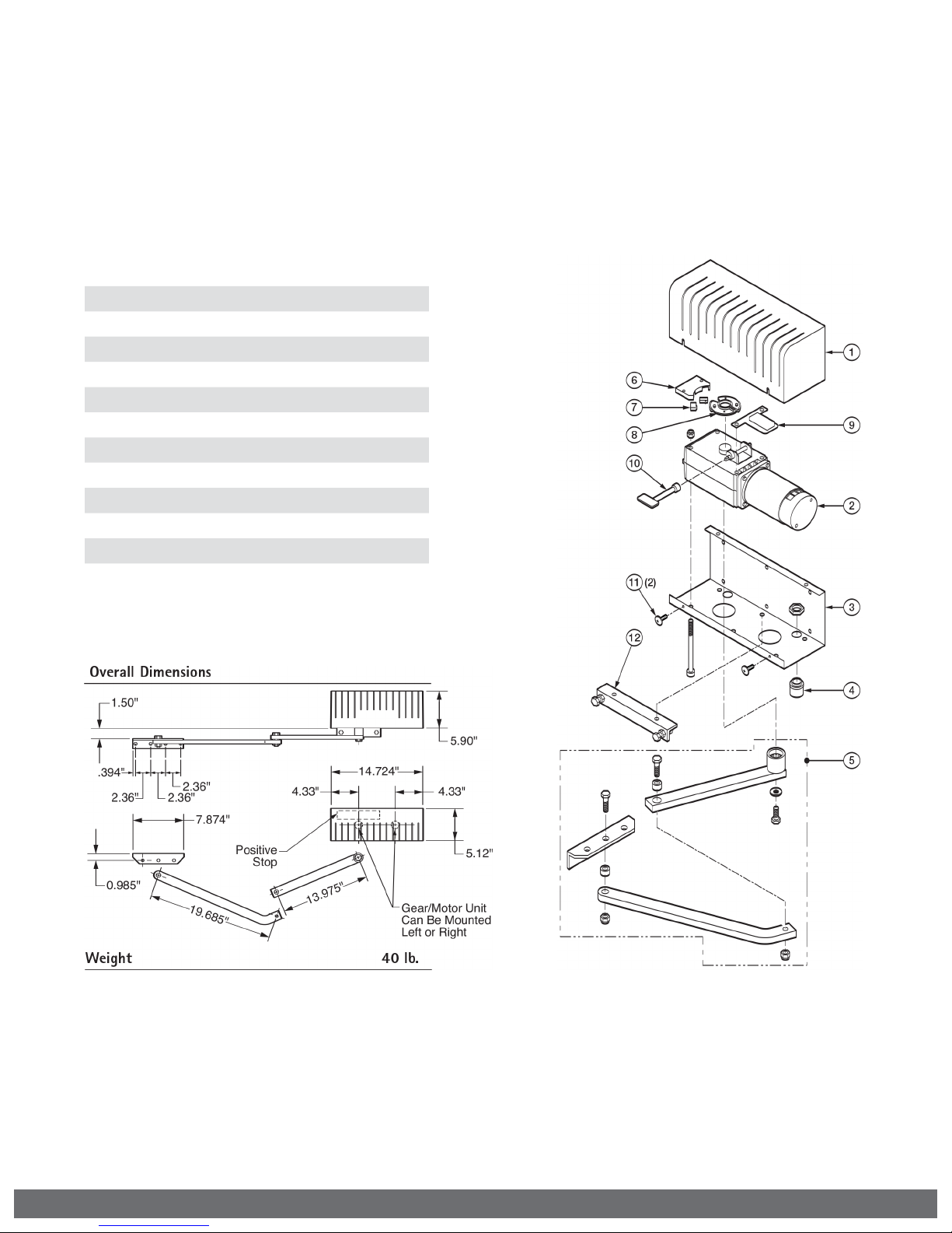
PARTS DIAGRAM - OPERATOR:
Item Description Part No.
1 Cover VAX9PC
2 Motor/Gear Assembly VX9MOSLR
3 Chassis VAX9CH
4 Strain Relief (X-9) VAX9ST
5 Arm Assembly, articulated VAX9AA
6 Limit Switch Holder VAX9LSH
7 Limit Switch (2) VAX9LS
8 Limit Cam & Holder VAX9LCS
9 Terminal Block (Motor) VAX9TB
10 Key Release VAX9KR
11 Cover Screw (2) VAX9CS
12 Positive Stop Extension VAX9PSE
2
VIKING TECHNICAL SUPPORT 1.800.908.0884
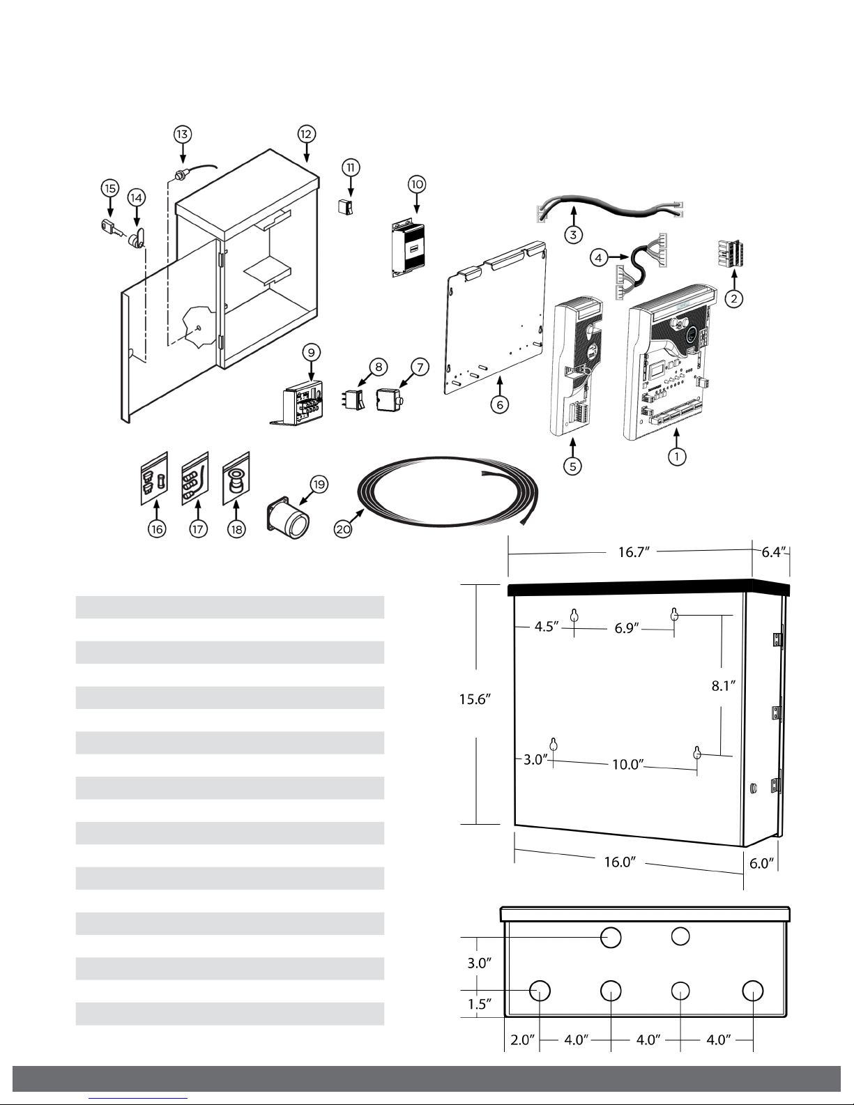
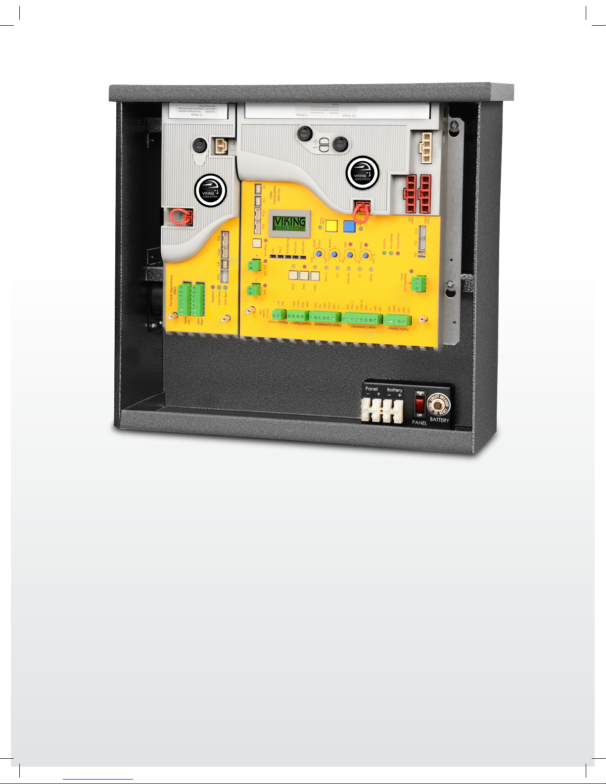
PARTS DIAGRAM - ECU BOX:
Item Description Part No.
1 Solar Control Board VSPCBU16
2 Motor Connector - Master VECUMCM
3 Slave Power Harness (Dual Controller only) VECUSPH
4 Master/Slave Comm Cable (Dual Controller only) VECUMSC
5 Slave Solar Module (Dual Controller only) VSSMPCBU16
6 Board Mounting Plate VECUBMP
7 Solar Battery Breaker VASBB25
8 Solar Panel Switch DUMRS5
9 Solar Terminal Block Assembly VSTBAECU
10 Solar Charger VSCHARGECU
11 Power Switch DUMRS10
12 ECU Cabinet Chassis VNXECUBB
13 Alarm Reset Switch ECURW
14 ECU Key Cylinder & Key(s) ECUKEYC20
15 ECU Access Key(s) ECUKEY20
16 Fuse Kit DUFSKNX
17 Radio Antenna Kit VARAK
18 Strain Relief (ECU) DH3/4NMCC
19 Alarm DUAL10
20 6 Conductor Cable, 16 AWG Shielded VA-CB16
VIKING TECHNICAL SUPPORT 1.800.908.0884
3
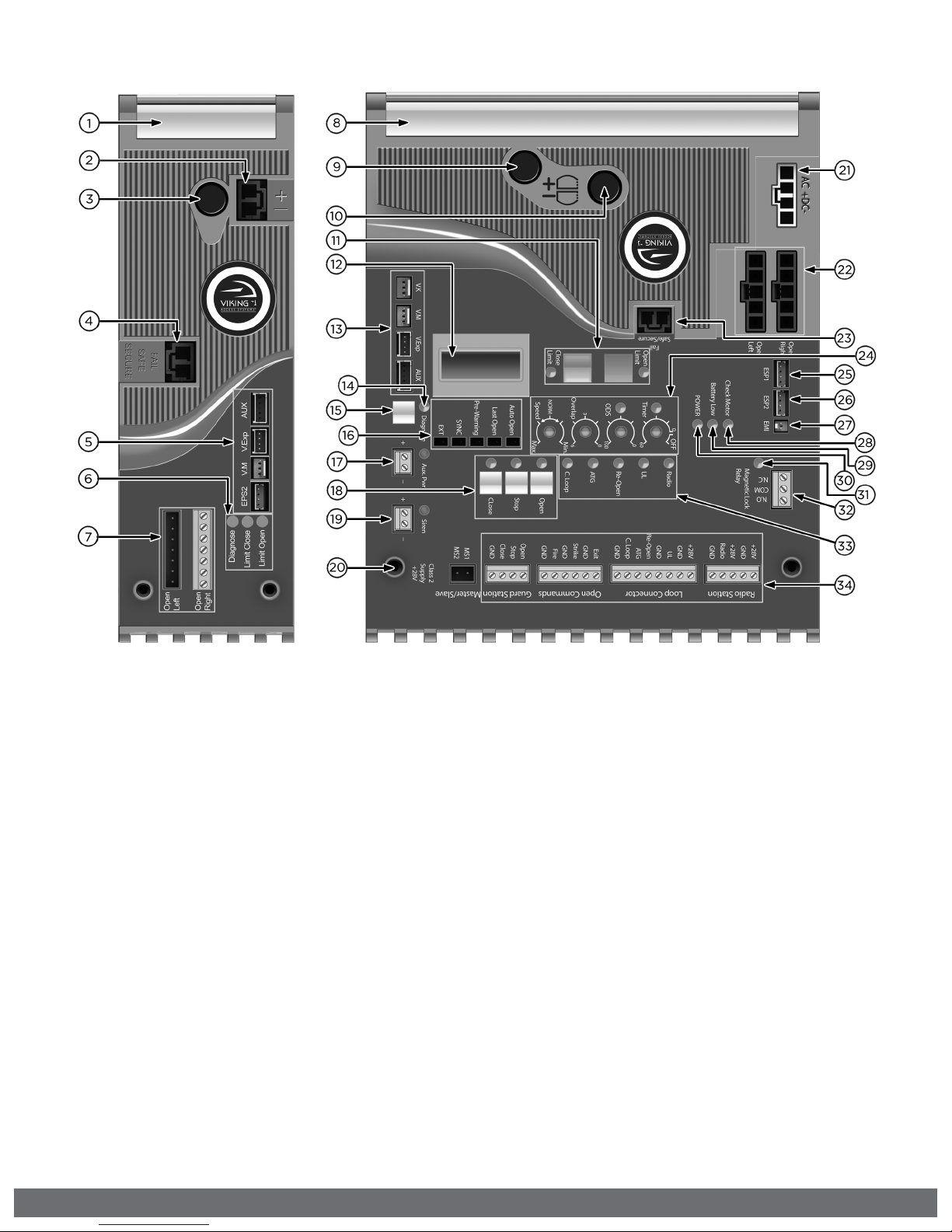
CONTROL BOARD REFERENCES:
1.
HEAT SINK - SLAVE MODULE
secures the control board and dissipates heat.
2.
SLAVE MODULE POWER HARNESS CONNECTOR
provides power to the Slave Module. pg 23
3.
FUSE HOLDER - 15 AMP
for the Slave motor circuit.
4.
“FAIL SAFE/SECURE” Jumper - SLAVE MODULE
power failure option. pg 26
5.
M/S COMM CABLE CONNECTION - SLAVE MODULE
for master/slave (dual) gate application. pg 23
6.
STATUS LEDs - SLAVE MODULE
provides diagnostic information.
7.
SLAVE MOTOR CONNECTION
provides power to the Slave motor. pg 23
8.
HEAT SINK - MASTER/SINGLE
secures the control board and dissipates heat.
9.
FUSE HOLDER - 4 AMP
not applicable to this model.
10.
FUSE HOLDER - 15 AMP
for the Master motor circuit.
11.
LIMIT SETUP BUTTONS
available for future developments.
12.
LCD DIAGNOSTICS DISPLAY
provides error messages, diagnostics settings
and operator status information. pg 36-38
13.
M/S COMM CABLE CONNECTION - MASTER BOARD
for master/slave (dual) gate application. pg 23
14.
“DIAGNOSE” LED
informs that errors have been detected and
available on LCD Display. pg 36-38
15.
“DIAGNOSE” Button
allows you to navigate through the
Diagnostics LCD Display. pg 36-38
16.
FEATURE ACTIVATION PIN HEADERS
activate features by placing a jumper onto the
pin headers. pg 26
17.
“AUX. PWR” Terminal Block
used for solar applications & in-motion
warning devices. pg 21, 26
18.
ON-BOARD 3 BUTTON STATION
controls the gate during set up.
19.
“Siren” TERMINAL BLOCK
Vikings UL Siren is connected here. pg 12, 27
20.
CONTROL BOARD MOUNTING HOLES
secures and grounds the control board.
21.
POWER HARNESS CONNECTOR
provides power to the control board. pg 21
22.
MASTER or SINGLE MOTOR CONNECTION
provides power to the motor. pg 22
23.
“FAIL SAFE/SECURE” Jumper
power failure option. pg 26
24.
FEATURE ACTIVATION TRIM POTS
activate and set features. pg 25
25.
“EPS1” CONNECTOR
communication for Viking Solar Charger.
26.
“EPS2” CONNECTOR
available for future developments.
27.
“EMI” CONNECTOR
not applicable to this model.
28.
“CHECK MOTOR” Status LED
indicates motor power status. pg 34
29.
“BATTERY LOW” Status LED
indicates battery power status. pg 34
30.
“POWER” Status LED
control board power status. pg 34
31.
“MAGNETIC LOCK Relay” Status LED
status of this on-board relay. pg 34
32.
“MAGNETIC LOCK Relay” Terminal Block
connect electric locks here. pg 34
33.
INPUT STATUS LEDs
indicates input status. pg 34-35
34.
ACCESS CONTROL TERMINAL BLOCKS
accessory connections. pg 28-31, 40-42
4
VIKING TECHNICAL SUPPORT 1.800.908.0884
TABLE OF CONTENTS:
PARTS DIAGRAM/PARTS LIST 2-3
CONTROL BOARD REFERENCES 4
IMPORTANT SAFETY INFORMATION 6-12
Important Safety Instructions 6
Important Installation Instructions 7
Maintenance 8
General Safety Precautions 8-9
Operator Classification 9
Secondary Entrapment Protection Requirements 10
Secondary Entrapment Protection Installation 11
Manual Release 11
Audible Alarm Reset Installation 12
Warning Placard Installation 12
IMPORTANT INSTALLATION INFORMATION 13
Specifications 13
GATE OPERATOR INSTALLATION 14-17
Pull to Open Installation 14
Push to Open Installation 15
Mounting the Gate Operator 16
Limit Switch Setup 17
ECU BOX INSTALLATION 18
ELECTRICAL INSTALLATION 19-23
Battery & Solar Panel Selection 19
Solar Panel Care & Installation Tips 20
Solar Connection & Power Saving Tips 21
Motor Cable 22-23
LIMIT INDICATIONS 24
CONTROL BOARD SETUP 25-27
Initial Settings 25-26
Obstruction Detection Sensor (Primary Entrapment Protection) 27
ACCESSORY CONNECTIONS 28-33
Re-Open Photo Beam (Vehicular Safety) 28
Radio Receiver (Typical) 29
Anti-Tailgate, Open Commands, Guard Station 30
Viking Loop Rack 31
Guidelines for Loop Installations 32
Barrier Arm (B-12) Synchronization Option 33
TROUBLESHOOTING 34-39
LED References 34-35
LCD Display References 36-38
Solutions 39
APPENDIX A, B & C 40-43
VIKING EXPANSION PRODUCTS 44
VIKING TECHNICAL SUPPORT 1.800.908.0884
5

IMPORTANT SAFETY INFORMATION
! WARNING! Not Following these instructions may cause severe injury or death.
IMPORTANT SAFETY INSTRUCTIONS
! WARNING! To reduce the risk of severe injury or death.
1.
READ AND FOLLOW ALL INSTRUCTIONS.
2.
Never let children operate or play with gate controls. Keep the remote away
from children.
3.
Always keep people and objects away from the gate. NO ONE SHOULD
CROSS THE PATH OF THE MOVING GATE.
4.
Test the gate operator monthly. The gate MUST reverse on contact with
a rigid object or when an object activates the non-contact sensors. After
adjusting the force or the limit travel, retest the gate operator. Failure to
adjust and retest the gate operator properly can increase the risk of injury or
death.
5.
Use the emergency release only when the gate is not moving.
6.
KEEP GATES PROPERLY MAINTAINED. Read the user’s manual. Have a
qualified service person make repairs to gate hardware.
7.
The entrance is for vehicles only. Pedestrians must use a separate entrance.
8.
Every gate operator installation MUST have secondary protection devices
against entrapment, such as edge sensors and photo beams more in
particularly in places where the risk of entrapment is more likely to occur.
9.
SAVE THESE INSTRUCTIONS.
IMPORTANT INSTALLATION INSTRUCTIONS
1.
Install the gate operator only when:
a.
The operator is appropriate for the construction of the gate and usage
Class of the gate (refer to page 9),
b.
All openings of a horizontal slide gate are guarded or screened from the
bottom of the gate to a minimum of 6 feet (1.83 m) above the ground to
prevent a 2-1/4 inch (57.2 mm) diameter sphere from passing through the
openings anywhere in the gate, and in that portion of the adjacent fence
that the gate covers in the open position,
c.
ALL EXPOSED PINCH POINTS ARE ELIMINATED OR GUARDED, AND
d.
GUARDING IS SUPPLIED FOR EXPOSED ROLLERS.
2.
The Operator is intended for installation only on gates used for vehicles.
Pedestrians must be supplied with a separate access opening. The pedestrian
access opening shall be designed to promote pedestrian usage. Locate the
gate such that persons will not come into contact with the vehicular gate
during the entire path of travel of the vehicular gate.
3.
The gate must be installed in a location so that enough clearance is supplied
between the gate and adjacent structures when opening and closing to
reduce the risk of entrapment. Swinging gates shall not open in to the public
access areas.
4.
The gate must be properly installed and work freely in both directions prior to
the installation of the gate operator. Do not over-tighten the operator clutch
or pressure relief valve to compensate for a damaged gate.
5.
The gate operator controls must be placed so that the user has full view of
the gate area when the gate is moving AND AWAY FROM THE GATE PATH
PERIMETER.
6
VIKING TECHNICAL SUPPORT 1.800.908.0884

IMPORTANT SAFETY INFORMATION
! WARNING! Not Following these instructions may cause severe injury or death.
IMPORTANT INSTALLATION INSTRUCTIONS (Continued)
6.
Controls intended for user activation must be located at least six feet (6’)
away from any moving part of the gate and where the user is prevented from
reaching over, under, around or through the gate to operate the controls.
Exception: Emergency access controls only accessible by authorized personnel
(i.e. fire, police, EMS) may be placed at any location in the line-of-sight of the
gate.
7.
The Stop and/or Reset button must be located in the line-of-sight of the gate.
Activation of the reset control shall not cause the operator to start.
8.
A minimum of two (2) WARNING SIGNS shall be installed, in the area of the
gate. Each placard is to be visible by persons located on the side of the gate on
which the placard is installed.
9.
For gate operators using non-contact sensors (photoelectric beam or like) in
accordance with section 31.1.1 of the UL standard:
a.
See instructions on the placement of non-contact sensors for each type of
application (refer to page 10).
b.
Care shall be exercised to reduce the risk of nuisance tripping, such as
when a vehicle, trips the sensor while the gate is still moving, and
c.
One or more non-contact sensors shall be located where the risk of
entrapment or obstruction exists, such as the perimeter reachable by a
moving gate or barrier (refer to page 10).
d.
Use only Miller Edge photoelectric beams (refer to pages 10-11).
10.
For a gate operator utilizing a contact sensor (edge sensor or like) in
accordance with section 31.1.1 of the UL 325 standard:
a.
One or more contact sensors shall be located where the risk of entrapment
or obstruction exists, such as a the leading edge, trailing edge, and post
mounted both inside and outside of a vehicular horizontal slide gate (refer
to page 10).
b.
One or more contact sensors shall be located at the bottom of a vehicular
vertical lift gate.
c.
One or more contact sensors shall be located at the pinch point of a
vehicular vertical pivot gate.
d.
A hardwired contact sensor shall be located and its wiring arranged so
that the communication between the sensor and the gate operator is not
subject to mechanical damage.
e.
A wireless contact sensor such as one that transmits radio frequency
(RF) signals to the gate operator for entrapment protection functions
shall be located where the transmission of the signals are not obstructed
or impeded by building structures, natural landscaping or similar
obstructions. A wireless contact sensor shall function under the intended
end-use conditions.
f.
One or more contact sensors shall be located on the inside and outside
leading edge of a swing gate. Additionally, if the bottom edge of a swing
gate is greater than 6 inches (152 mm) but less than 16 inches (406 mm)
above the ground at any point in its arc of travel, one or more contact
sensors shall be located on the bottom edge.
g.
One or more contact sensors shall be located at the bottom edge of a
vertical barrier (arm).
h.
Use only Miller Edge edge sensor (refer to pages 10-11).
VIKING TECHNICAL SUPPORT 1.800.908.0884
7

IMPORTANT SAFETY INFORMATION
! WARNING! Not Following these instructions may cause severe injury or death.
MAINTENANCE
Remove the Power Harness from the Control Board. (refer to page 21)
• Clean and lubricate the turning pins and gate hinges using the recommended
lubricant.
• Check that all mounting hardware of the gate operator is properly tighten.
• Ensure that the gate moves freely.
• Check for corroded parts and replace if necessary.
• Check the battery for the following:
- Battery connections must be free of corrosion.
- Battery voltage must be 13VDC (fully charged battery).
Reconnect the Power Harness for the Control Board. (refer to page 21)
• Check and confirm the proper operation of all safety devices (photoelectric
eye, edge sensors or like).
• Check and confirm the operation of all installed accessories.
• Check and confirm the operation of all special features such as the Intelligent
Obstruction Sensor, Hold Open Timer. (refer to page 25 and 27)
• Check and confirm the operation of the manual release. (refer to page 11)
GENERAL SAFETY PRECAUTIONS
The following precautions are an integral and essential part of the product and must be
supplied to the user. Read them carefully as they contain important indications for the
safe installation, use and maintenance.
• These instruction must be kept and forwarded to all possible future users of the
system.
• This product must be used only for that which it has been expressly designed.
• Any other use is to be considered improper and therefore dangerous.
• The manufacturer cannot be held responsible for possible damage caused by
improper, erroneous or unreasonable use.
• Avoid operating in the proximity of the hinges or moving mechanical parts.
• Do not enter the path of the moving gate while in motion.
• Do not obstruct the motion of the gate as this may cause a situation of danger.
• Do not allow children to play or stay within the path of the moving gate.
• Keep remote control or any other control devices out of the reach of children, in
order to avoid possible involuntary activation of the gate operator.
• In case of break down or malfunctioning of the product, disconnect from the main
power source. Do not attempt to repair or intervene directly, contact only qualified
personnel for repair.
• Failure to comply with the above may create a situation of danger.
• All cleaning, maintenance or repair work must be carried out by qualified personnel.
• In order to guarantee that the system works efficiently and correctly it is important
to have the manufacturer’s instructions on maintenance of the gate and operator
carried out by qualified personnel.
• In particular, regular checks are recommended in order to verify that the safety
devices are operating correctly.
All installation, maintenance and repair work must be documented and made
available to the user.
8
VIKING TECHNICAL SUPPORT 1.800.908.0884
IMPORTANT SAFETY INFORMATION
! CAUTION: To Reduce the Risk of Fire or Injury to Persons:
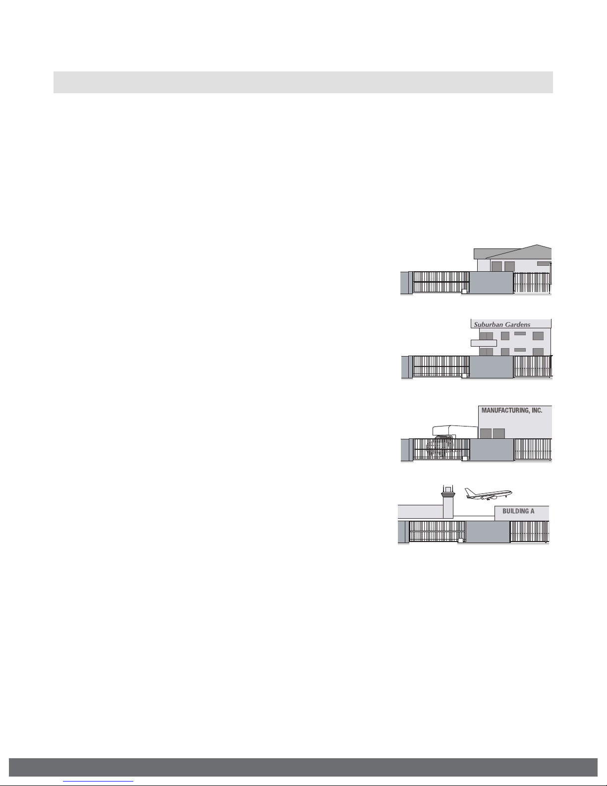
UL325 Gate Operator Classifications
GLOSSARY
RESIDENTIAL VEHICULAR GATE OPERATOR
CLASS I - A vehicular gate operator (or system) intended
for use in garages or parking areas associated with a
residence of one-to four single families.
COMMERCIAL/GENERAL ACCESS VEHICULAR GATE OPERATOR
CLASS II – A vehicular gate operator (or system)
intended for use in a commercial location or building
such as a multi-family housing unit (five or more single
family units), hotel, garages, retail store, or other
building servicing the general public.
INDUSTRIAL/LIMITED ACCESS VEHICULAR GATE OPERATOR
CLASS III – A vehicular gate operator (or system)
intended for use in an industrial location or building
such as a factory or loading dock area or other
locations not accessible by or intended to service the
general public.
RESTRICTED ACCESS VEHICULAR GATE OPERATOR
CLASS IV – A vehicular gate operator (or system)
intended for use in a guarded industrial location or
building such as an airport security area or other
restricted access locations not servicing the general
public, in which unauthorized access is prevented via
supervision by security personnel.
Install the gate operator only when:
The operator is appropriate for the construction of the gate and the Usage Class of
the gate.
VIKING TECHNICAL SUPPORT 1.800.908.0884
9
IMPORTANT SAFETY INFORMATION
! WARNING! Not Following these instructions may cause severe injury or death.
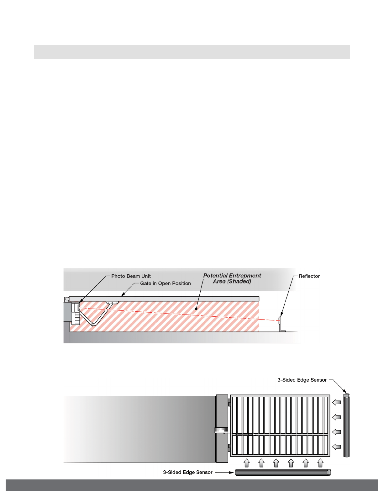
Secondary Entrapment Protection Requirements
IMPORTANT: SECONDARY PROTECTION MUST BE INSTALLED
•
REQUIRED BY UL 325, an approved MONITORED secondary entrapment
protection sensor is REQUIRED to be installed in all areas accessible to potential
entrapment and pinch points.
•
The installed sensor MUST be “10K Resistor Based”.
•
At least ONE monitored sensor MUST be connected. (also, refer to page 43)
•
You may connect up to FOUR monitored sensors, wired parallel.
•
Failure to install an approved monitored secondary entrapment protection
sensor will render the gate operator INOPERABLE until one is installed.
•
Consult the installation manual of the sensor for detailed information about the
usage, installation and maintenance.
•
This type of installation will only reverse the gate approximately 12” in the opposite
direction it was traveling when the sensor is triggered. (also, refer to page 43)
•
This type on installation is to protect against entrapment only and DOES NOT
reverse the gate all the way back to its limits when the sensor is triggered. (also,
refer to page 43)
•
Use only UL Listed Edge Sensor and Photoelectric Beams.
Photo Beam (non-contact sensor)
Edge Sensor (contact sensor)
10
VIKING TECHNICAL SUPPORT 1.800.908.0884
IMPORTANT SAFETY INFORMATION
! WARNING! Not Following these instructions may cause severe injury or death.
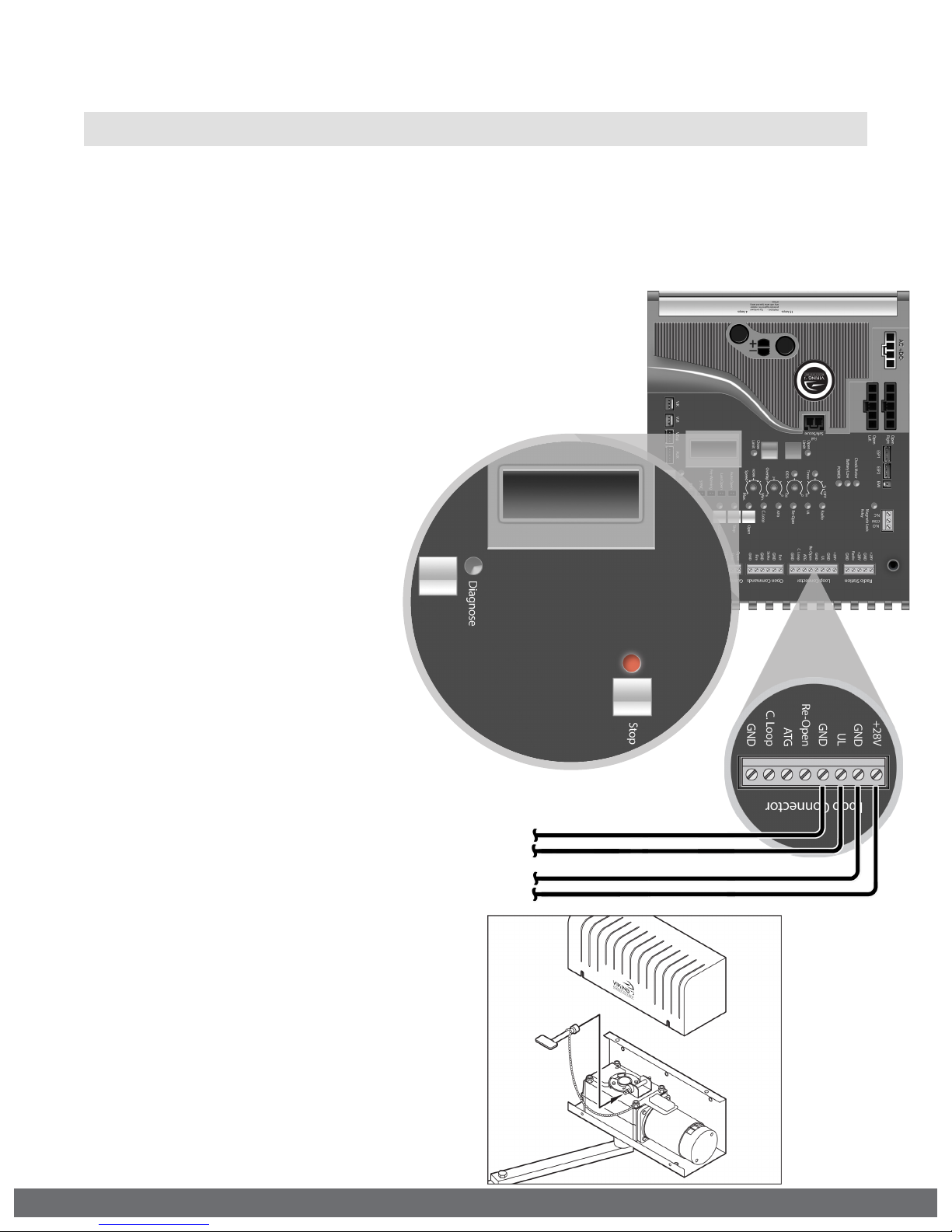
Secondary Entrapment Protection Installation
STEP 1
Connect the secondary entrapment protection sensor(s) to the Viking control board as
illustrated below. Up to four 10K resistor based sensors can be wired in parallel.
STEP 2
Confirm the number of sensors connected:
•
Toggle the “Diagnose” button until you see UL LEARN
on the LCD Display.
•
Default setting is 1 sensor.
Proceed with the following Learn Process:
•
If the number of connected sensors does
not match the display.
•
If the “Stop” LED is flashing.
•
If the error message ERR UL SENSOR
is displayed.
UL LEARN
UL LEARN
SENSOR 1
SENSOR 1
LEARN PROCESS
With the “UL LEARN” menu
displayed and all secondary sensors
properly connected to the control
board:
•
Press and hold the “Stop” button.
•
Toggle the “Diagnose” button
once.
•
The correct number of sensors
should now be displayed.
10K (Sensor’s Monitored Terminals)
24VDC (may not be required on all sensors)
Manual Release
When manual operation is required:
1.
Use the attached Key to rotate the
gear release mechanism counterclockwise.
2.
To reengage the gear, rotate the
gear release mechanism clockwise.
DO NOT rotate the gear release
mechanism in any direction while the
motor is running.
VIKING TECHNICAL SUPPORT 1.800.908.0884
11
IMPORTANT SAFETY INFORMATION
! WARNING! Not Following these instructions may cause severe injury or death.
Audible Alarm Reset Switch Installation
Manual Reset for the Audible Alarm
•
UL325 standard requires an audible alarm to sound after two consecutive events
detected by the primary entrapment protection of the gate operator (obstruction
sensor).
•
The audible alarm will continue to sound for 5 minutes or until a stop command
gets actuated.
•
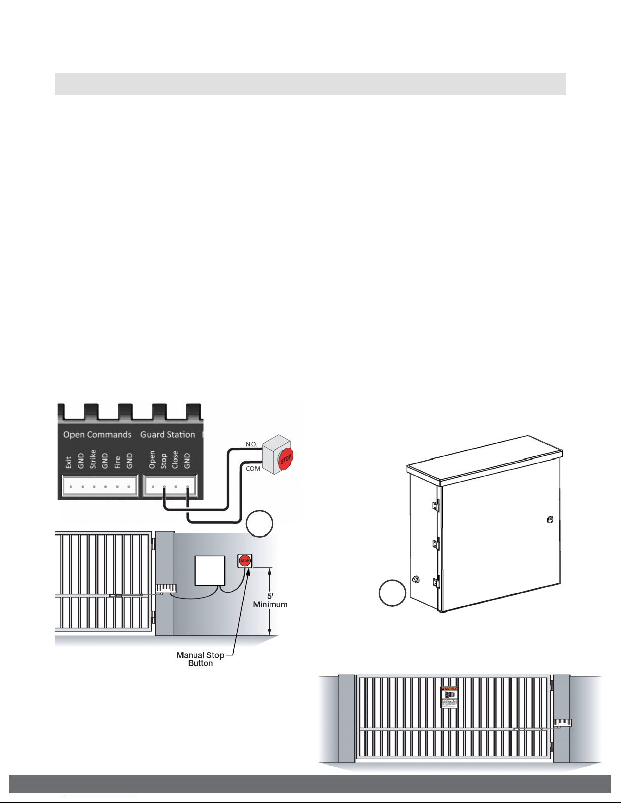
The Stop command can be actuated in three different forms:
1.
Using the Built in Stop switch on the Control Board; or
2.
Using an External Stop button within the sight of the gate, away from moving
parts of the gate and out of reach of children.
a.
Controls intended for user activation must be located at least six feet (6’)
away from any moving part of the gate and where the user is prevented from
reaching over, under, around, or through the gate to operate the controls.
Outdoor or easily accessible controls shall have a security feature to prevent
unauthorized use.
b.
The Stop and/or Reset button must be located in the line-of-sight of the gate.
Activation of the reset control shall not cause the operator to start.
3.
Using the Reset Button on the Electronic Control Unit that is externally
accessible on the left side of the cabinet.
Warning Placard Installation
•
All Warning Placards must be installed
where visible in the area of the gate.
•
A minimum of two placards shall be
installed.
•
A placard is to be installed in the area of
each side of the gate and be visible.
12
2
3
VIKING TECHNICAL SUPPORT 1.800.908.0884
IMPORTANT INSTALLATION INFORMATION
! CAUTION: To Reduce the Risk of Fire or Injury to Persons:
! WARNING: For use with gates at a maximum 600 lbs. in weight or 14 ft. in length.
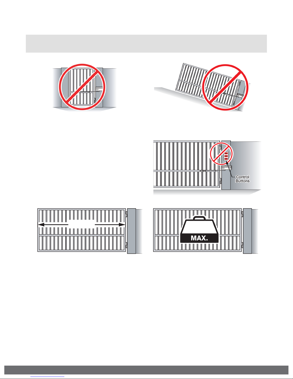
DO NOT allow pedestrian use of this gate DO NOT install the gate operator to lift gates
Locate Control Buttons:
1.
Within sight of the gate,
2.
At a minimum height of 5 feet
so small children are not able to
reach it; and
3.
At least 6 feet away from all
moving parts of the gate.
14 ft.
X-9S Specications:
UL Application Class: Class I
Maximum Gate Length: 14 ft.
Maximum Gate Weight: 600 lb.
Operating Temperature: -4°F (-20°C) to 160°F (71°C)
600 lb.
VIKING TECHNICAL SUPPORT 1.800.908.0884
13
 Loading...