

Viking X-9 Installation Instructions And Safety Information

Vehicular Gate Operator
UL 325 and UL991 Listed
Class I, Class II, Class III and Class IV
Installation Instructions and Safety Information
Rev. A.1 March 2005
TECHNICAL SUPPORT 1 800 908 0884
i
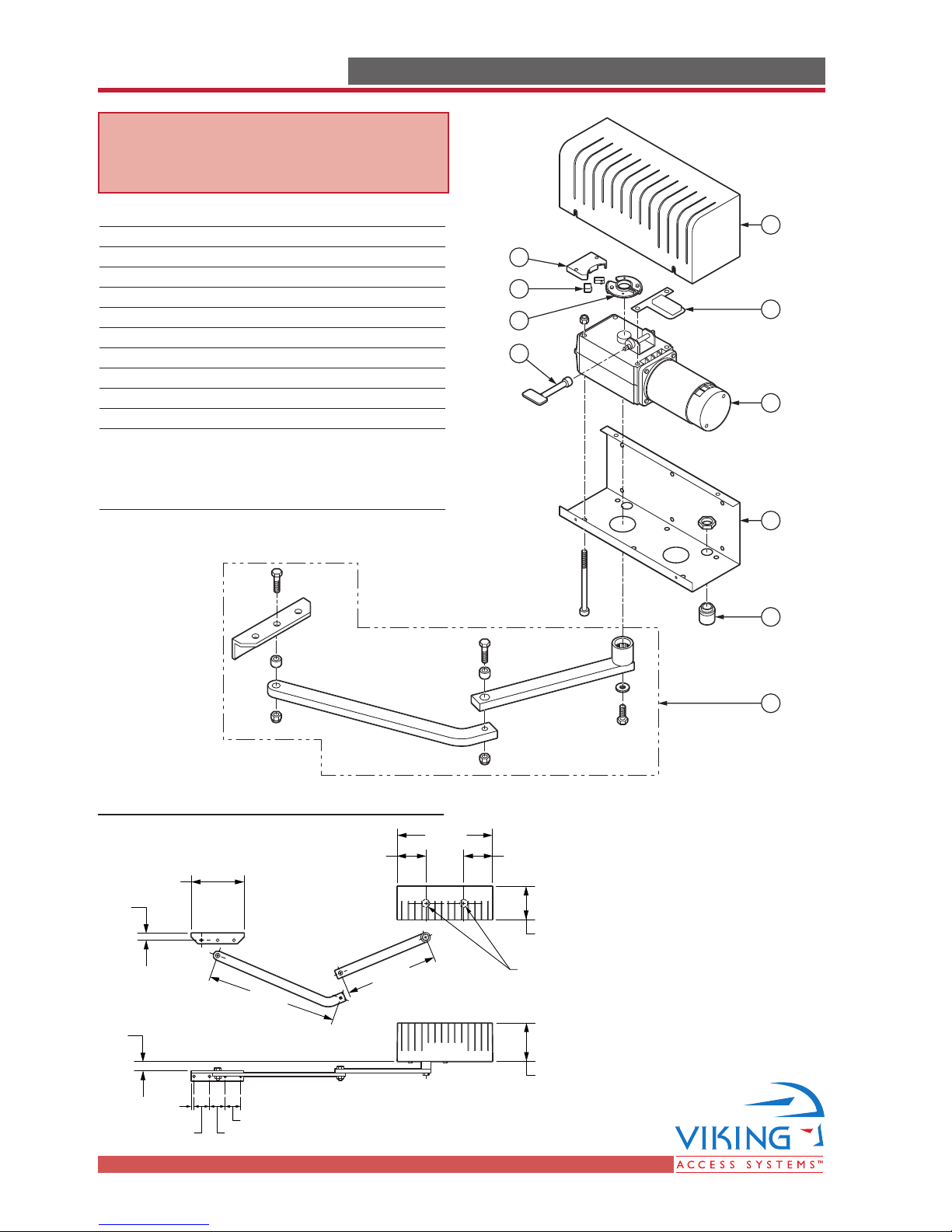
PARTS DIAGRAMPARTS DIAGRAM
Item Description
Part No.
1 Cover, Plastic VAX9PC
2 Motor/Gear Unit VAX9
3 Chassis, Motor/Gear VAX9CH
4 Strain Relief VAX9ST
5 Arm Assembly, Articulated VAX9AA
6 Holder, Limit Switch
7 Limit Switch (2) VAX9LS
8 Cam, Limit Switch VAX9LCS
9Terminal Block VAX9TB
10
Key Release VAX9KR
Weight 40 lb.
Overall Dimensions
14.724"
13.975"
19.685"
7.874"
4.33" 4.33"
5.12"
.985"
Gear/Motor Unit
Can Be Mounted
Left or Right
5.90"
1.50"
.394"
2.36"
2.36"2.36"
WARNING - For Installation
By Qualified Personnel Only.
10
1
6
7
8
9
2
3
4
5

TECHNICAL SUPPORT 1 800 908 0884
1
TABLE OF CONTENTSTABLE OF CONTENTS
Parts Diagram/Parts List . . . . . . . . . . . . . . . . . . . . . . . . . . . . . . . . . . . . . . . . .i
Important Safety Information
Important Safety Instructions . . . . . . . . . . . . . . . . . . . . . . . . . . . . . . . . . . . .2
Important Installation Instructions . . . . . . . . . . . . . . . . . . . . . . . . . . . . . . . .2-3
Maintenance/General Safety Precautions . . . . . . . . . . . . . . . . . . . . . . . . . . . .4
Terminology . . . . . . . . . . . . . . . . . . . . . . . . . . . . . . . . . . . . . . . . . . . . . . . .5
Photo Beam (non-contact sensor) Installation . . . . . . . . . . . . . . . . . . . . . . . . .6
Edge Sensor (contact sensor) Installation . . . . . . . . . . . . . . . . . . . . . . . . . . . .7
Manual Release . . . . . . . . . . . . . . . . . . . . . . . . . . . . . . . . . . . . . . . . . . . . . .7
Audible Alarm Reset Switch Installation . . . . . . . . . . . . . . . . . . . . . . . . . . . . .8
Warning Placard Installation . . . . . . . . . . . . . . . . . . . . . . . . . . . . . . . . . . . .8
Important Installation Information . . . . . . . . . . . . . . . . . . . . . . . . . . . . . . . .9
Specifications . . . . . . . . . . . . . . . . . . . . . . . . . . . . . . . . . . . . . . . . . . . . . . .9
Plan of Installation – Open Inside . . . . . . . . . . . . . . . . . . . . . . . . . . . . . . . . . .10
Plan of Installation – Open Outside . . . . . . . . . . . . . . . . . . . . . . . . . . . . . . . .11
Gate Operator Installation
Step 1 through 7 – Operator Installation . . . . . . . . . . . . . . . . . . . . . . . . . . . .13
Step 8 through 9 – Limit Switch Setup . . . . . . . . . . . . . . . . . . . . . . . . . . . . .14
Opening/Closing Setup . . . . . . . . . . . . . . . . . . . . . . . . . . . . . . . . . . . . . . . .15
Reference Wiring Diagram; Limit Switch Connections . . . . . . . . . . . . . . . . . . .15
Control Box Installation . . . . . . . . . . . . . . . . . . . . . . . . . . . . . . . . . . . . . . . . .16
Electrical Installation
Electrical Installation (120/220 VAC) . . . . . . . . . . . . . . . . . . . . . . . . . . . . . . .17
Single Unit Connections . . . . . . . . . . . . . . . . . . . . . . . . . . . . . . . . . . . . . . .18
Master/Slave Connections . . . . . . . . . . . . . . . . . . . . . . . . . . . . . . . . . . . . . .19
Vehicular Loop Detector Installation
Loop Layout Diagrams . . . . . . . . . . . . . . . . . . . . . . . . . . . . . . . . . . . . . . . .20
Installation Guidelines . . . . . . . . . . . . . . . . . . . . . . . . . . . . . . . . . . . . . . . .21
Accessory Connections
Open Commands; Safety Connections . . . . . . . . . . . . . . . . . . . . . . . . . . . . . .22
Radio Receiver; Hold Open Timer . . . . . . . . . . . . . . . . . . . . . . . . . . . . . . . . .23
Magnetic Lock; Solenoid; Guard Station . . . . . . . . . . . . . . . . . . . . . . . . . . . .24
Special Features
Intelligent Obstruction Sensor (Primary Entrapment Protection) . . . . . . . . . . . .25
Gate Overlap Setting . . . . . . . . . . . . . . . . . . . . . . . . . . . . . . . . . . . . . . . . . .27
Troubleshooting . . . . . . . . . . . . . . . . . . . . . . . . . . . . . . . . . . . . . . . . . . . . .28-29

TECHNICAL SUPPORT 1 800 908 0884
2
WARNING - Not following these instructions may cause severe injury or death to persons.
IMPORTANT SAFETY INFORMATIONIMPORTANT SAFETY INFORMATION
IMPORTANT SAFETY INSTRUCTIONS
WARNING – To reduce the risk of severe injury or death:
1. READ AND FOLLOW ALL INSTRUCTIONS.
2. Never let children operate or play with gate controls. Keep the remote control away from children.
3. Always keep people and objects away from the gate. NO ONE SHOULD CROSS THE PATH OF
THE MOVING GATE.
4. Test the gate operator monthly. The gate MUST reverse on contact with a rigid object or when
an object activates the non-contact sensors. After adjusting the force or the limit of travel,
retest the gate operator. Failure to adjust and retest the gate operator properly can increase the
risk of injury or death.
5. Use the manual release only when the gate is not moving.
6. KEEP GATES PROPERLY MAINTAINED. Read the owner’s manual. Have a qualified service per-
son make repairs to gate hardware.
7. The entrance is for vehicles only. Pedestrians must use separate entrance.
8. Every gate operator installation MUST have secondary protection devices against entrapment,
such as edge sensors and photo beams more in particularly in places where the risk of entrapment is more likely to occur.
9. SAVE THESE INSTRUCTIONS.
IMPORTANT INSTALLATION INSTRUCTIONS
1. Install the gate operator only when:
a) The operator is appropriate for the construction of the gate and the usage Class of the gate
(refer to page 5),
b) All openings of a horizontal slide gate are guarded or screened from the bottom of the gate
to a minimum of 4 feet (1.22 m) above the ground to prevent a 2-1/4 inch (57.2 mm)
diameter sphere from passing through the openings anywhere in the gate, and in that
portion of the adjacent fence that the gate covers in the open position,
c) ALL EXPOSED PINCH POINTS ARE ELIMINATED OR GUARDED, AND
d) GUARDING IS SUPPLIED FOR EXPOSED ROLLERS.
2. The operator is intended for installation only on gates used for vehicles. Pedestrians must be
supplied with a separate access opening.
3. The gate must be installed in a location so that enough clearance is supplied between the gate
and adjacent structures when opening and closing to reduce the risk of entrapment. Swinging
gates shall not open into public access areas.
4. The gate must be properly installed and work freely in both directions prior to the installation
of the gate operator. Do not over-tighten the operator clutch or pressure relief valve to compensate for a damaged gate.

TECHNICAL SUPPORT 1 800 908 0884
3
WARNING - Not following these instructions may cause severe injury or death to persons.
IMPORTANT SAFETY INFORMATIONIMPORTANT SAFETY INFORMATION
5. The gate operator controls must be placed so that the user has full view of the gate area when
the gate is moving AND AWAY FROM THE GATE PATH PERIMETER,
6. Controls must be far enough from the gate so that the user is prevented from coming in contact
with the gate while operating the controls. Controls intended to be used to reset an operator
after 2 sequential activations of the entrapment protection device or devices must be located in
the line-of-sight of the gate. Outdoor or easily accessible controls shall have a security feature
to prevent unauthorized use.
7. All warning signs and placards must be installed where visible in the area of the gate. A minimum
of two placards shall be installed. A placard is to be installed in the area of each side of the
gate and be visible to persons located on the side of the gate on which the placard is installed.
8. For gate operators utilizing a non-contact sensor (Photo beam or like) in accordance with section
31.1.1 of the UL325 standard:
a) See instructions on the placement of non-contact sensors for each Type of application (refer
to page 6),
b) Care shall be exercised to reduce the risk of nuisance tripping, such as when a vehicle, trips
the sensor while the gate is still moving, and
c) One or more non-contact sensors shall be located where the risk of entrapment or obstruc-
tion exists, such as the perimeter reachable by a moving gate or barrier (refer to page 6).
9. For a gate operator utilizing a contact sensor (Edge sensor or like) in accordance with section
31.1.1 of the UL325 standard:
a) One or more contact sensors shall be located where the risk of entrapment or obstruction
exists, such as at the leading edge, trailing edge, and post mounted both inside and outside
of a vehicular horizontal slide gate (refer to page 7).
b) One or more contact sensors shall be located at the bottom edge of a vehicular vertical lift gate.
c) One or more contact sensors shall be located at the pinch point of a vehicular vertical pivot gate.
d) A hardwired contact sensor shall be located and its wiring arranged so that the communication
between the sensor and the gate operator is not subjected to mechanical damage.
e) A wireless contact sensor such as one that transmits radio frequency (RF) signals to the gate
operator for entrapment protection functions shall be located where the transmission of the
signals are not obstructed or impeded by building structures, natural landscaping or similar
obstruction. A wireless contact sensor shall function under the intended end-use conditions.
f) One or more contact sensors shall be located on the inside and outside leading edge of a
swing gate. Additionally, if the bottom edge of a swing gate is greater than 6 inches (152
mm) above the ground at any point in its arc of travel, one or more contact sensors shall be
located on the bottom edge (refer to page 7).
g) One or more contact sensors shall be located at the bottom edge of a vertical barrier (arm).
IMPORTANT INSTALLATION INSTRUCTIONS Continued

TECHNICAL SUPPORT 1 800 908 0884
4
WARNING - Not following these instructions may cause severe injury or death to persons.
IMPORTANT SAFETY INFORMATIONIMPORTANT SAFETY INFORMATION
GENERAL SAFETY PRECAUTIONS
The following precautions are an integral and essential part of the product and must be supplied to the user.
Read them carefully as they contain important indications for the safe installation, use and maintenance.
• These instruction must be kept and forwarded to all possible future users of the system.
• This product must be used only for that which it has been expressly designed.
• Any other use is to be considered improper and therefore dangerous.
• The manufacturer cannot be held responsible for possible damage caused by improper, erroneous or
unreasonable use.
•Avoid operating in the proximity of the hinges or moving mechanical parts.
• Do not enter the path of the moving gate while in motion.
• Do not obstruct the motion of the gate as this may cause a situation of danger.
• Do not allow children to play or stay within the the path of the moving gate.
•Keep remote control or any other control devices out of the reach of children, in order to avoid possible
involuntary activation of the gate operator.
• In case of break down or malfunctioning of the product, disconnect from the main power source. Do not
attempt to repair or intervene directly, contact only qualified personnel for repair.
• Failure to comply with the above may create a situation of danger.
• All cleaning, maintenance or repair work must be carried out by qualified personnel.
• In order to guarantee that the system works efficiently and correctly it is important to have the manufacturer’s
instructions on maintenance of the gate and operator carried out by qualified personnel.
• In particular, regular checks are recommended in order to verify that the safety devices are operating correctly.
All installation, maintenance and repair work must be documented and made available to the user.
Installer:
_____________________________________________________ ____________
Signature Date
Contact: _________________________________________________________
_________________________________________________________
MAINTENANCE
Remove the Power Harness from the Control Board (refer to page 17)
• Clean and lubricate the turning pins and gate hinges using the recommended lubricant.
• Check that all mounting hardware of the gate operator is properly tighten.
• Ensure that the gate moves freely.
• Check for corroded parts and replace if necessary.
• Check the battery for the following:
Battery connections must be free of corrosion.
Battery voltage must be 26 VDC (fully charged battery).
Reconnect the Power Harness for the Control Board (refer to page 17)
• Check and confirm the proper operation of all safety devices (photoelectric eye, edge sensors or like).
• Check and confirm the operation of all installed accessories.
• Check and confirm the operation of all special features such as the Intelligent Obstruction Sensor, Hold
Open Timer (refer to page 20 to 27)
• Check and confirm the operation of the manual release (refer to page 7)
•Verify battery backup functionally by turning off the power source (120 VAC and 220 VAC). DO NOT
FORGET TO TURN ON THE POWER SOURCE AFTER VERIFICATION.
TECHNICAL SUPPORT 1 800 908 0884
55
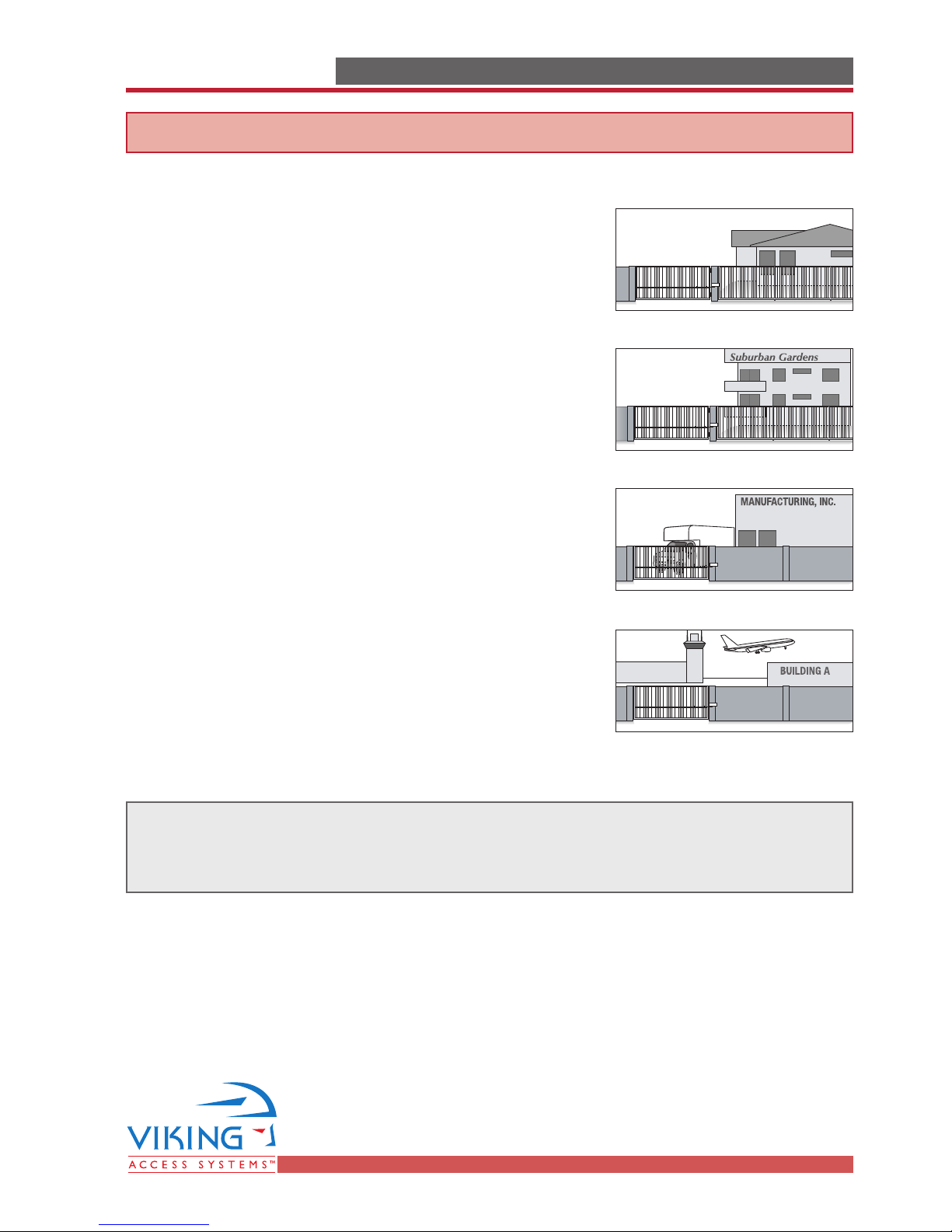
UL325 Gate Operator Classification
TERMINOLOGYTERMINOLOGY
GLOSSARY
RESIDENTIAL VEHICULAR GATE OPERATOR
CLASS I – A vehicular gate operator (or system) intended for use
in a home of one-to four single family dwelling, or a garage or
parking area associated therewith.
COMMERCIAL/GENERAL ACCESS VEHICULAR GATE OPERATOR
CLASS II – A vehicular gate operator (or system) intended for use
in a commercial location or building such as a multi-family housing unit (five or more single family units), hotel, garages, retail
store, or other building servicing the general public.
INDUSTRIAL/LIMITED ACCESS VEHICULAR GATE OPERATOR
CLASS III – A vehicular gate operator (or system) intended for
use in an industrial location or building such as a factory or
loading dock area or other locations not intended to service the
general public.
RESTRICTED ACCESS VEHICULAR GATE OPERATOR
CLASS IV – A vehicular gate operator (or system) intended for
use in a guarded industrial location or building such as an airport security area or other restricted access locations not servicing the general public, in which unauthorized access is prevented
via supervision by security personnel.
Install the gate operator only when:
The operator is appropriate for the construction of the gate and the Usage
Class of the gate.

TECHNICAL SUPPORT 1 800 908 0884
6
WARNING - Not following these instructions may cause severe injury or death to persons.
IMPORTANT SAFETY INFORMATIONIMPORTANT SAFETY INFORMATION
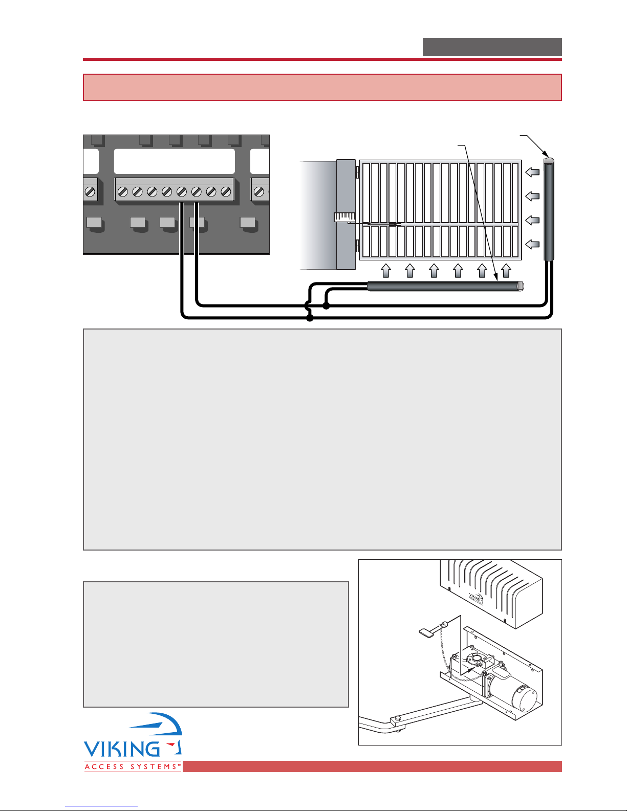
Photo Beam (non-contact sensor) Installation
a
a
N
One or more non-contact sensors shall be located where
the risk of entrapment or obstruction exists, such as the
perimeter reachable by a moving gate or barrier.
Consult the installation manual for the UL325 device
(photo beam or like) for detail information about the
usage, installation and maintenance
1
(C1)3(NC1)
24VDC
1
(C1)3(NC1)
24VDC
Turn Switch to
'Light On' Position
24 VDC Power Connections
24 VDC Power Connections
Omron Model
E3K-R10
Shown
Connection '3' (NC1)
Connection '1' (C1)
Photo beams or like must be installed to reduce the risk of entrapment.
Use only UL325 compliance devices like:
Omron E3K-R10
Ensure that any device installed is UL325 compliant and low voltage device (24 VDC).
Read the device manual for proper installation, and proper connection (especially
the polarity of the device).
Ma
Ma
Gnd
Exit
Safety Connectorands Radio St
Safety Connectorands
Gnd
Center
Gnd
Safety
GndULGnd
+28v
Photo Beam Unit Reflector
Radio St
Gnd
Radio
+28v
Gate in Open Position
Potential Entrapment
Area (Shaded)
TECHNICAL SUPPORT 1 800 908 0884
7
a
s
a
s
WARNING - Not following these instructions may cause severe injury or death to persons.
IMPORTANT SAFETY INFORMATIONIMPORTANT SAFETY INFORMATION
Edge Sensor (contact sensor) Installation
Edge sensor or like must be installed to reduce the risk of entrapment.
Use only UL325 compliance devices like:Use only UL325 compliance devices like:
Miller Edge 3-sided activation for an added measure of protection MGR20 or MGS20
If you install another device:
a) Ensure its compliance with UL325,
b) Use the recommended supply voltage,
c) Follow the installation guidelines of the device.
One or more contact sensors shall be located on the inside and outside leading edge
of a swing gate. Additionally, if the bottom edge of a swing gate is greater than 6
inches (152 mm) above the ground at any point in its arc of travel, one or more
contact sensors shall be located on the bottom edge.
Consult the installation manual for the UL325 device (photo beam or like) for detail
information about the usage, installation and maintenance.
Manual Release
When manual operation is required:
Remove the cover, locate the chained key and
turn the key to push the locking-pin down.
At end of operations, lock the geared motor again
by releasing locking-pin.
Attention: Lock and release operations MUST
be performed with motor NOT RUNNING.
3-Sided Edge Sensor
3-Sided Edge Sensor
Exit
Safety Connector
Safety Connector
Gnd
Center
Gnd
Safety
GndULGnd
+28v
Gnd
R
R
TECHNICAL SUPPORT 1 800 908 0884
8
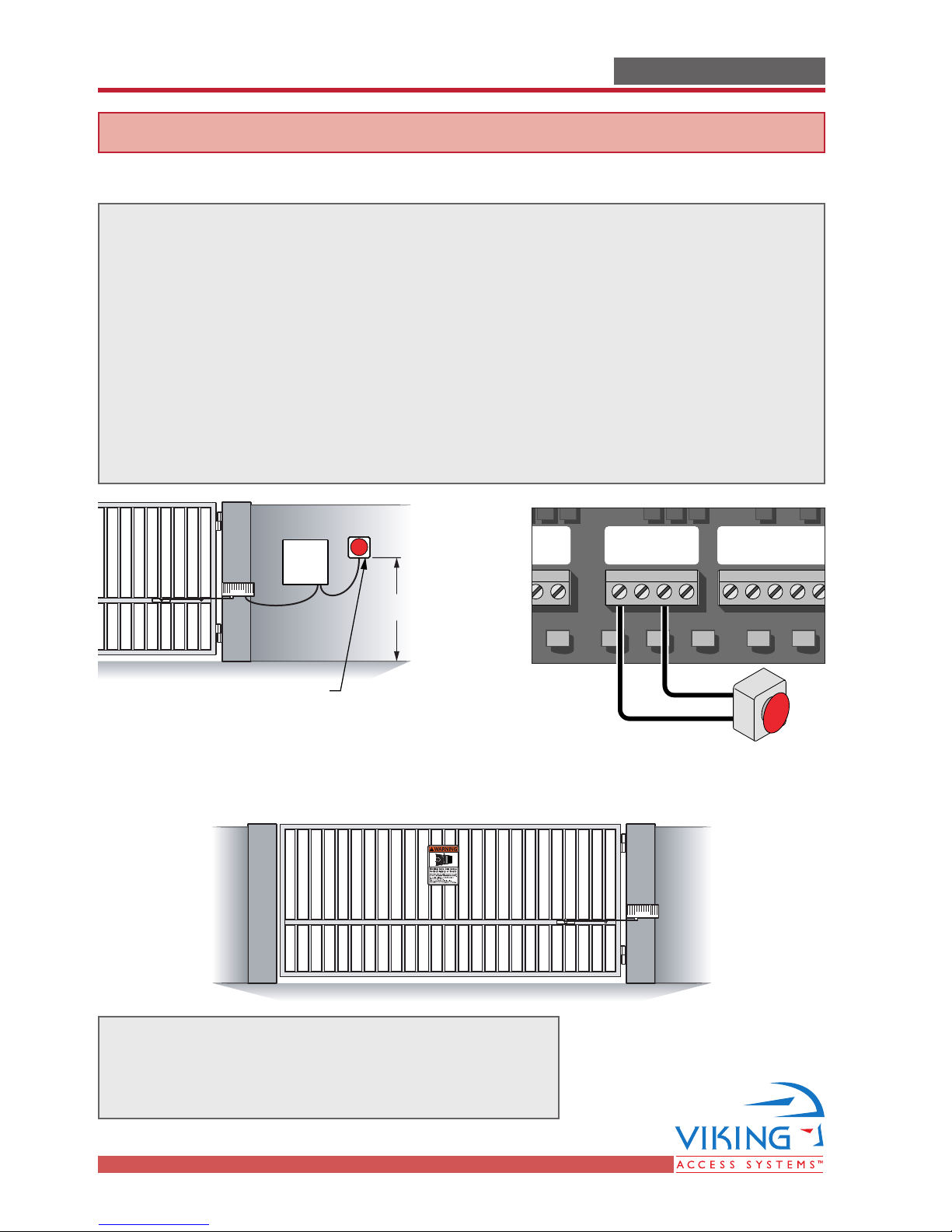
Audible Alarm Reset Switch Installation
Reset for the Audible Alarm
UL325 standard requires an audible alarm to go off after two consecutive events
detected by the primary entrapment protection of the gate operator (obstruction sensor).
The audible alarm will continue to sound for 5 minutes or until a stop command
gets actuated.
The Stop command can be actuated in two different forms
1. Using the built in stop switch in the control board or
2. Using an external stop button within the sight of the gate, away from moving
parts of the gate and out of reach of children.
WARNING - Not following these instructions may cause severe injury or death to persons.
IMPORTANT SAFETY INFORMATIONIMPORTANT SAFETY INFORMATION
Warning Placard Installation
d
d
All warning signs and placards must be installed where
visible in the area of the gate. A minimum of two
placards shall be installed. A placard is to be installed
in the area of each side of the gate and be visible.
STOP
5'
Minimum
Manual Stop
Button
N.O.
Open Comman
Gnd
Fire
Gnd
STOP
Strike
Slave Open Comman
Slave
Stop
Open
Guard Station
Guard Station
GND
Close
Stop
Open
COM
Gnd
 Loading...