

Page 1
PPrraaccttiicce
e
T
T
EELLEECCOOM
M
S
S
OOLLUUTTIIOONNSSFFOORRTTHHE
E
221
1
SST
T
C
C
EENNTTUURRY
Y
TECHNICAL
TECHNICAL
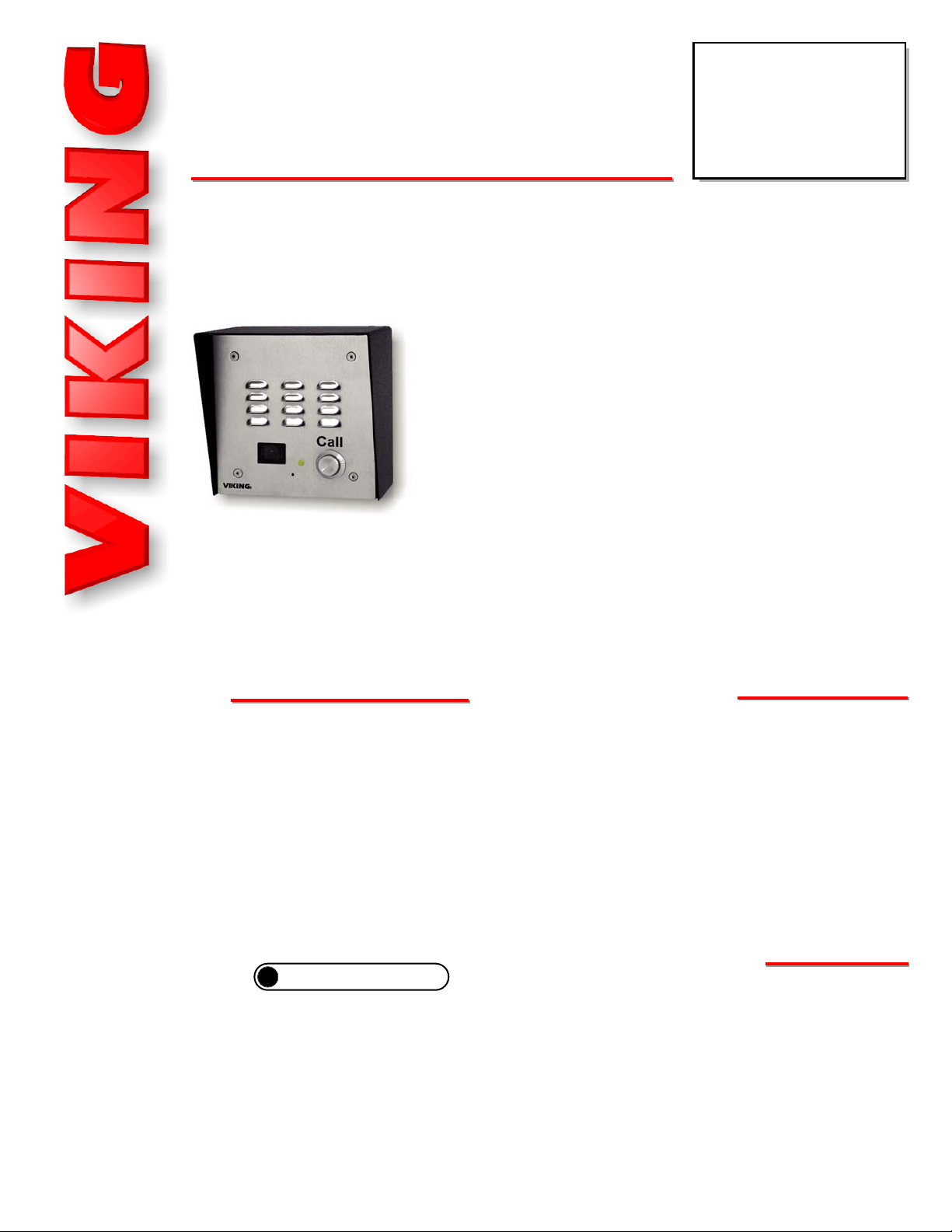
Vandal Resistant Handsfree Doorbox with
Built-In Color Video Camera
Answer your door or gate from the safety of your telephone!
The W-3005 is a weather resistant, handsfree video doorbox
designed to provide quick and reliable handsfree communication
and CCTV video of who is at your door or gate. The W-3005 can
interface directly with the unused telephone line input of nearly
any phone system. One or two doorboxes can also share an
existing residential phone line when used with a C-1000B door-
box controller.
When the “Call“ button is pressed, the doorbox generates a
standard or custom ring cadence of an adjustable number of
rings. For noisy environments, the doorbox’s new louder speak-
FFeeaattuurrees
s
PPhhoonnee......771155..338866..8888661
1
Power: 120V AC/13.8V AC 1.25A UL listed adapter provided
Dimensions: Overall - 127mm x 127mm x 57.2mm (5.0” x 5.0”
x 2.25”) Plastic Rough-In Box - 102mm x 102mm x 54mm (4.0” x
4.0” x 2.12”)
Shipping Weight: 1.45 Kg (3.2 lbs)
Operating Temperature: -26°C to 54°C (-15°F to 130°F)
Humidity: W-3005 - 5% to 95% non-condensing humidity,
W-3005-EWP - Up to 100% condensing humidity
Connections: W-3005 - (4) position screw terminal strip and (3)
gel filled butt connectors (3M Scotchlok UR2), W-3005-EWP - (7)
Gel filled butt connectors (3M Scotchlok UR2)
(See page 2 for complete specifications)
SSppeecciiffiiccaattiioonns
s
er output and “Push-to-Talk” feature can be used.
The W-3005-EWP shares all of the features of the W-3005 in addition to Enhanced Weather
Protection (EWP) for installation in harsh environments. EWP products feature rubber gaskets
and boots, hand soldered silicon sealed connections, gel filled butt connectors, urethane potted
circuit boards with internally sealed, field adjustable trim pots and DIP switches for easy on-site
programming.
W-3005/
W-3005/
W-3005-EWP
W-3005-EWP
Vandal Resistant
Handsfree Video Doorbox
December 15, 2008
• Built-in high resolution color video camera with wide viewing
angle, tilt/swivel adjustments and wide operating temperature
of -30°F to 150°F
• Audio and video transmission on one CAT5E cable
• Vandal Resistant Features: 14 gauge louvered stainless
steel faceplate with stainless steel speaker/mic screen,
heavy duty metal “Call” button, impact and scratch resistant
camera lens and hex drive mounting screws
• Weather Resistant Features: Mylar speaker, faceplate
gasket, mic and speaker gasket, internally sealed (IP67)
push button switch, sealed camera lens, potted camera
circuit board, stainless steel phone and camera
mounting hardware
• Optional Enhanced Weather Protection (EWP) conforms to
NEMA requirements
• Volume adjustments for
microphone and speaker
• Yellow call progress/night light LED
• High output speaker amplifier with volume adjustment POT
• 20 Hz ring generator (3.0 REN ring load maximum)
• Selectable ring cadence (standard or 2 short rings)
• Selectable number of rings (2, 3, 10 or 30)
• Selectable “Push-to-Talk” feature for noisy environments
• Optional VE-5x5 surface mount box available
AApppplliiccaattiioonns
s
• Ideal for noisy locations in “Push-to-Talk” mode
• Commercial, industrial or residential door security
• Door or gate communication
• Truck stop/gas station fuel island communication
• Use with the C-1000B controller for single line residential systems or when the operation of door strikes or
gate openers is necessary
W-3005 shown with
optional VE-5x5
hhttttpp::////wwwwww..vviikkiinnggeelleeccttrroonniiccss..ccoom
m
?
Need More Information on EWP?
Call (715) 386-4345 and select 859.
Page 2

2
W
Waarrrraannttyy
IF YOU HAVE A PROBLEM WITH A VIKING PRODUCT
PLEASE CONTACT: VIKING TECHNICAL SUPPORT AT (715) 386-8666
Our Technical Support Department is available for assistance Monday 8am - 4pm and Tuesday to Friday 8am - 5pm central time. So that we can give you better service, before you call please:
1. Know the model number, the serial number and what software version you have (see serial label).
2. Have your Technical Practice in front of you.
3. It is best if you are on site.
RETURNING PRODUCT FOR REPAIR
The following procedure is for equipment that needs repair:
1. Customer must contact Viking's Technical Support Department at 715-386-8666 to obtain a Return Authorization (RA)
number. The customer MUST have a complete description of the problem, with all pertinent information regarding the
defect, such as options set, conditions, symptoms, methods to duplicate problem, frequency of failure, etc.
2. Packing: Return equipment in original box or in proper packing so that damage will not occur while in transit. Static sensitive equipment such as a circuit board should be in an anti-static bag, sandwiched
between foam and individually boxed. All equipment should be wrapped to avoid packing material lodging in or stick-
ing to the equipment. Include ALL parts of the equipment. C.O.D. or freight collect shipments cannot be accepted. Ship
cartons prepaid to: Viking Electronics, 1531 Industrial Street, Hudson, WI 54016
3. Return shipping address: Be sure to include your return shipping address inside the box. We cannot ship to a P.O. Box.
4. RA number on carton: In large printing, write the R.A. number on the outside of each carton being returned.
RETURNING PRODUCT FOR EXCHANGE
The following procedure is for equipment that has failed out-of-box (within 10 days of purchase):
1. Customer must contact Viking’s Technical Support at 715-386-8666 to determine possible causes for the problem. The
customer MUST be able to step through recommended tests for diagnosis.
2. If the Technical Support Product Specialist determines that the equipment is defective based on the customer's input
and troubleshooting, a Return Authorization (R.A.) number will be issued. This number is valid for fourteen (14) calen-
dar days from the date of issue.
3. After obtaining the R.A. number, return the approved equipment to your distributor, referencing the R.A. number. Your
distributor will then replace the product over the counter at no charge. The distributor will then return the product to
Viking using the same R.A. number.
4. The distributor will NOT exchange this product without first obtaining the R.A. number from you. If you haven't
followed the steps listed in 1, 2 and 3, be aware that you will have to pay a restocking charge.
LIMITED WARRANTY
Viking warrants its products to be free from defects in the workmanship or materials, under normal use and service, for a period of one year from the date of purchase
from any authorized Viking distributor or 18 months from the date manufactured, which ever is greater. If at any time during the warranty period, the product is deemed
defective or malfunctions, return the product to Viking Electronics, Inc., 1531 Industrial Street, Hudson, WI., 54016. Customer must contact Viking's Technical Support
Department at 715-386-8666 to obtain a Return Authorization (R.A.) number.
This warranty does not cover any damage to the product due to lightning, over voltage, under voltage, accident, misuse, abuse, negligence or any damage caused by
use of the product by the purchaser or others.
NO OTHER WARRANTIES
. VIKING MAKES NO WARRANTIES RELATING TO ITS PRODUCTS OTHER THAN AS DESCRIBED ABOVE AND DISCLAIMS ANY
EXPRESS OR IMPLIED WARRANTIES OR MERCHANTABILITY OR FITNESS FOR ANY PARTICULAR PURPOSE.
EXCLUSION OF CONSEQUENTIAL DAMAGES. VIKING SHALL NOT, UNDER ANY CIRCUMSTANCES, BE LIABLE TO PURCHASER, OR ANY OTHER PARTY,
FOR CONSEQUENTIAL, INCIDENTAL, SPECIAL OR EXEMPLARY DAMAGES ARISING OUT OF OR RELATED TO THE SALE OR USE OF THE PRODUCT SOLD
HEREUNDER.
EXCLUSIVE REMEDY AND LIMITATION OF LIABILITY
. WHETHER IN AN ACTION BASED ON CONTRACT, TORT (INCLUDING NEGLIGENCE OR STRICT LIABILITY) OR ANY OTHER LEGAL THEORY, ANY LIABILITY OF VIKING SHALL BE LIMITED TO REPAIR OR REPLACEMENT OF THE PRODUCT, OR AT VIKING'S
OPTION, REFUND OF THE PURCHASE PRICE AS THE EXCLUSIVE REMEDY AND ANY LIABILITY OF VIKING SHALL BE SO LIMITED.
IT IS EXPRESSLY UNDERSTOOD AND AGREED THAT EACH AND EVERY PROVISION OF THIS AGREEMENT WHICH PROVIDES FOR DISCLAIMER OF WARRANTIES, EXCLUSION OF CONSEQUENTIAL DAMAGES, AND EXCLUSIVE REMEDY AND LIMITATION OF LIABILITY, ARE SEVERABLE FROM ANY OTHER PROVISION AND EACH PROVISION IS A SEPARABLE AND INDEPENDENT ELEMENT OF RISK ALLOCATION AND IS INTENDED TO BE ENFORCED AS SUCH.
Page 3
Camera Specifications
Power: 5-9V DC regulated 150mA (6V DC adapter included)
Image Sensor: 1/4” color CMOS
Video Output: 1 VP-P composite, NTSC, 75 ohms
Resolution: 420 lines (640 x 480 @ 30fps / 307,200 pixels)
Sensitivity: 0.26 LUX (20 IRE) F 2.0
Lens: 3.4mm, pinhole 70° FOV (Field of View)
Tilt/Swivel Adjustment: Vertical +/- 20°, horizontal +/- 30° (see Diagram A)
Maximum Wire Run Length: 1000 ft with *RG59/RG6 for video and CAT5 for
power (doubled pairs) and entry phone audio. 150 ft with CAT5E for video,
power and entry phone audio (longer video runs are possible by using video
balun transceivers, see Installation section F, page 5).
* Note: RG59 or RG6 with solid center conductor and 95% bare copper braid
shield.
SSppeecciiffiiccaattiioonns
s
Doorbox Specifications
Power: 120V AC/13.8V AC 1.25A UL listed adapter provided
Dimensions: Overall - 127mm x 127mm x 57.2mm (5.0” x 5.0”
x 2.25”) Plastic Rough-In Box - 102mm x 102mm x 54mm (4.0” x
4.0” x 2.12”)
Shipping Weight: 1.81 Kg (4 lbs)
Ringer Output: 20 Hz, 3.0 REN load maximum
Maximum Loop Length: 1.9 Km (6300 ft) - 24 AWG twisted pair
Maximum Power Run: 38.1 m (125 ft) - 24 AWG twisted pair
Note: Power run length may be increased, see Wiring section.
Doorbox / Camera Specifications
Operating Temperature: -26° C to 54° C (-15° F to 130° F)
Humidity: Standard model: 5% to 95% non-condensing, EWP
model: Up to 100%
Connections: Standard model: (3) gel-filled butt connectors (3M
Scotchlok UR2), EWP model: (5) gel-filled butt connectors (3M
Scotchlok UR2)
Recommended Surface Mount Box: Viking model VE-5x5 (Fax
Back Document 424)
70° Lens FOV
Rotate
Left 30°
Rotate
Right 30°
Camera Lens
Diagram A
Camera Field of View:
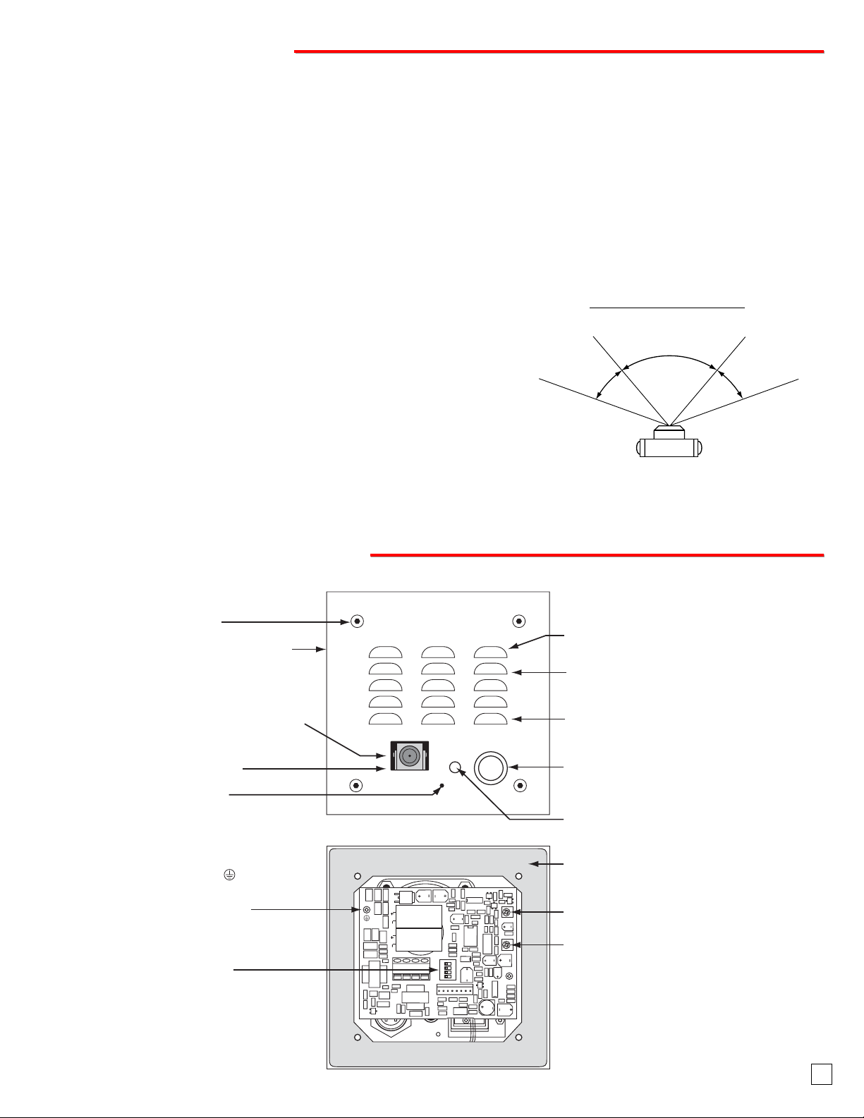
FFeeaattuurreessOOvveerrvviieew
w
3
Mounting Screws: 6-32 x 0.75" long
flathead with 5/64" hexdrive, 18-8 stainless
steel to prevent corrosion.
Faceplate: 14 gauge 304 stainless steel.
Color Video Camera: Wide operating
temperature range of -30°F to 150°F, NTSC
composite video output with 420 lines of
resolution, 70° wide viewing angle lens, tilt and
swivel adjustments for aiming towards visitors.
Protective Camera Window: Impact resistant
polycarbonate lens with scratch resistant
coating and water-tight gasket.
Condensation Drain Hole
Earth Ground: To increase surge protection,
loosen the screw labeled (as shown) and
fasten a wire with spade terminal (included)
from the mounting screw to Earth Ground
(grounding rod, water pipe, etc.)
DIP Switches (see page 5):
1: Ring Cadence
2 & 3: Ring Count
4: Communication Mode
VIKING
Microphone: Omni-directional microphone
with protective water-resistant cloth.
Speaker: Mylar speaker with rubber gasket to
maintain water-tight seal and eliminate water
deterioration.
Speaker Screen: Stainless steel speaker
screen with 0.018" diameter holes to prevent
Call
©
punctures from paperclips, etc.
Push Button Switch: Push to initiate call,
push again to disconnect. Solid 304 stainless
steel internally sealed per IP67.
LED: Lights yellow for "Call Progress /
Night Light" indication.
Faceplate Gasket: 1/8" thick closed cell PVC
to provide a water-tight seal.
Speaker Volume
Microphone Volume
Page 4

IMPORTANT: Electronic devices are susceptible to lightning and power station elec-
trical surges from both the AC outlet and the telephone line. It is recommended that
a surge protector be installed to protect against such surges. Contact Panamax at (800)
472-5555 or Electronic Specialists Inc. at (800) 225-4876.
!
Important: Do NOT install a W-3005 on a
telephone line without a C-1000B Controller
(Fax Back Document 155).
** Note: To increase surge protection, loosen the PCB mounting screw labeled (as shown above) and fasten a wire with spade terminal (included) from the mounting screw to Earth Ground (grounding rod, water pipe, etc.)
* Note: The gel-filled (water-tight) butt connectors are designed for insulation displacement on 19-26 guage wire with a maximum insulation of 0.082
inches. Do not strip wires prior to terminating.
*** Warning: The doorbox power run wire length is limited to 125 ft of 24 AWG wire. Longer power runs will require heavier gauge wire (doubling
pairs) and/or a higher voltage power adapter. Power runs from 125 - 250 ft of 24 AWG wire are possible using a Radio Shack 18VAC adapter (part
# 273-1690). Voltage at the doorbox power input connections must not exceed 18VAC RMS.
B. Wiring the W-3005 Board
4
Front View of Optional
VE-5x5 (not included)
2.25”
Condensation
Drain Hole
* Adhere gasket to front panel,
centering over mounting holes
5.14”
5.22”
3.25”
Call
4.0"
Rear View of VE-5x5
(not included)
Push to Call Button
Yellow Call Progress LED Indicator
Condensation Drain Hole
(4) 6-32 X 3/4” stainless steel, flat
head, hexdrive, screws (included)
5.0”
W-3005 shown with
Viking Model
VE-GNP
Gooseneck
Pedestal
(4) 0.38” diameter
(for gooseneck mounting)
(4) 0.2 x 0.43 slots
for double gang box
(2) 0.2 x 0.43 slots
for single gang box
(1) .74" dia
3.0” 3.3”
3.0”
2.1”
Wall Stud
Front View of
Plastic Rough-In
Box (included)
Wire knock out
(2) Standard flat head dry wall
(sheet rock) screws (not included)
IInnssttaallllaattiioon
n
The optional VE-5x5 Surface Mount Box is designed
to be surface mounted to a single gang box, double
gang box or VE-GNP gooseneck pedestal (right).
Important: The W-3005 will NOT
mount to a standard double gang box.
Caution: When warm air comes in contact with cold surfaces, such as outside walls and conduits, it causes condensation. To prevent
condensation from accumulating inside the W-3005 always bring conduit into the bottom of the unit. If this is not possible, drill a 1/4” diameter hole in the bottom of the gray plastic box.
*Note: Peel off paper liner and adhere gasket to the back of the faceplate, centering it over the four corner mounting holes. Be careful
to position the modular jack inside the chassis as not to damage the components on the circuit board.
Note: The plastic rough-in box (part # 259576) may be purchased separately
in advance. Go to www.vikingelectronics.com and click on “Spare Parts”.
?
Need More Information on VE-5x5 or VE-GNP?
Call (715) 386-4345 and select 424.
IMPORTANT: Electronic devices are susceptible to lightning and power station electrical surges from both the AC outlet and the
telephone line. It is recommended that a surge protector be installed to protect against such surges. Contact Panamax at (800)
472-5555 or Electronic Specialists Inc. at (800) 225-4876.
!
A. Mounting
C-1000B Controller
C
A
V
.8
3
1
R
W
P
GND
C.O. LINE
INPUT
LINE OUT
PHONE LINE
INPUT
COM N.O. N.C. - - - -AUX.
SIG GND
VIDEO 2 IN
OUT TO
PHONES
VIDEO OUT
©
MODEL C-1000B
VIKING
ELECTRONICS
HUDSON, WI 54016
DOOR ENTRY / CCTV VIDEO
/ PAGING CONTROLLER
T
U
1
P
X
X
T
O
O
U
B
B
R
O
R
R
O
O
O
O
W
TO PHONES
KEYLESS CONTACT
CLOSURE INPUT
D
D
P
10 11 12 13
CONTACT
OUTPUT
SIG GND
C
TALK BATTERY
LED1
OFF ON
KEYLESS
DOOR
DOORBOX
C.C. INPUT
BOX 1
13VAC PWR
C.O.
Line
2
X
O
B
R
O
O
D
14 15 16 17 18 19
DOOR
N.O. COM N.C.
BOX 2
DOOR STRIKE 1
1
E
R
IK
O
R
O
T
D
S
ON
1 2 3
C
LED2CLED3
VIKING
EARTH
123456789
SIG GND
VIDEO 1 IN
EARTH
GND
N.O. COM N.C.
DOOR STRIKE 2
2
E
R
IK
O
R
O
T
D
S
Single Line
Phone
Multi-Line
Phone
PABX/KSU
Trunk Input
Unused
or
3.63" Typical
(Spade connector
included)
** Earth
Ground
(optional)
* Gel-filled butt
connectors
(EWP only)
*** 13.8VAC
(18VAC max)
3.63"
Rear View of
the W-3005
Gel-filled butt
connectors
(EWP only)
120V AC
Red
Green
Page 5

5
C. Using W-3005(s) and a C-1000B on a DSL Line
The C-1000B can be installed on a DSL line by using a DSL PJ31X Alarm Filter and single line DSL filters.
Recommended DSL Filters:
* Excelsus Z-Blocker Alarm Panel DSL Filter Z-A431PJ31X-A
** Excelsus Z-Blocker Single Line DSL Filter Z-275P2J
For technical information or to buy Excelsus Filters, go to www.excelsus-tech.com
Model C-1000B (not included)
* Z-Blocker
DSL
Alarm Filter
RJ31/38X
Cut & Strip
back jacket
Cat 5
Wire
RJ45X
ALARM PANEL
Cut off modular plug and
strip back gray jacket
VIKING
SIG GND
VIDEO 1 IN
EARTH
GND
Brown/White
Blue/White
(Inside pair)
Green/White
White/Orange
(Outside pair)
©
ELECTRONICS
HUDSON, WI 54016
DOOR ENTRY / CCTV VIDEO
AC
PWR 13.8 V
EARTH
GND
123456789
C.O. LINE
INPUT
/ PAGING CONTROLLER
LINE OUT
TO PHONES
PHONE LINE
INPUT
COM N.O. N.C. - - - - AUX.
SIG GND
SIG GND
VIDEO 2 IN
VIDEO OUT
OUT TO
KEYLESS
PHONES
C.C. INPUT
KEYLESS CONTACT
CLOSURE INPUT
DOORBOX 1
CONTACT
OUTPUT
C
LED1
DOOR
BOX 1
MODEL C-1000B
VIKING
DOORBOX 2
14 15 16 17 18 19
TALK BATTERY
OFF ON
DOOR
N.O. COM N.C.
BOX 2
DOOR STRIKE 1
DOOR
C
LED2CLED3
DOORBOX
PWR OUTPUT
10 11 12 13
DOORBOX
13VAC PWR
DOOR
STRIKE 1
ON
1 2 3
N.O. COM N.C.
DOOR STRIKE 2
** Standard
DSL Filter
Doorbox 2
Model W-3005
STRIKE 2
Doorbox 1
Model W-3005
C.O.
DSL
Modem
Line
** Standard
DSL Filter
Phone 1
** Standard
DSL Filter
** Standard
DSL Filter
Phone 2
(Inside pair)
Brown
LINE OUT
Gray
Red
LINE IN
Green
(Outside pair)
Computer
To additional
phones with
DSL Filters
Page 6

* Note: Up to 150 ft video cable run length can be achieved using CAT5E or CAT6 cable. Longer cable runs can be used if a passive or active video Balun transceiver is used on
each end of the cable. Generally, passive transceivers can achieve up to 750 ft cable runs where active transceivers can achieve up to 3000 ft runs depending on cable type, etc.
The type of video balun transceiver required is specific to your cable run length. For more information on video balun transceivers go to: www.northernvideo.com.
** Note: The maximum camera power supply wire run length is 500 ft of 24 gauge wire (CAT 5/6), longer runs are possible by doubling pairs or increasing the wire gauge.
*** Note: RG59 or RG6 with solid center conductor and 95% bare copper braid shield.
*** Warning: The doorbox power run wire length is limited to 125 ft of 24 AWG wire. Longer power runs will require heavier gauge wire (doubling
pairs) and/or a higher voltage power adapter. Power runs from 125 - 250 ft of 24 AWG wire are possible using a Radio Shack 18VAC adapter (part
# 273-1690). Voltage at the doorbox power input connections must not exceed 18VAC RMS.
Caution: When routing CAT5E or CAT6 cable, maintain a minimum distance of 3 ft from any parallel high voltage wire (110 VAC) and a minimum of 2 ft from crossing any high voltage wire. For installations where RF noise is expected (commercial applications) or wire runs are near high voltage (110 VAC) wires, a shielded video cable such as RG6 is recommended.
2. Using CAT5E or CAT6 for Video, Camera Power and Phone Board Audio (see Caution below)
D. Wiring the W-3005 Camera
1. Using RG59 for Video and CAT5 for Camera Power and Phone Board Audio (Recommended)
* Warning: The doorbox power run wire length is limited to 125 ft of 24 AWG wire. Longer power runs will require heavier gauge wire (doubling pairs)
and/or a higher voltage power adapter. Power runs from 125 - 250 ft of 24 AWG wire are possible using a Radio Shack 18VAC adapter (part # 273-
1690). Voltage at the doorbox power input connections must not exceed 18VAC RMS.
** Note: The maximum camera power supply wire run length is 500 ft of 24 gauge wire (CAT 5/6), longer runs are possible by doubling pairs or increasing the wire gauge.
*** Note: RG59 or RG6 with solid center conductor and 95% bare copper braid shield.
6
Back View of the W-3005
3-Wire Gel-Filled Butt Connectors
included (3M Scotchlok UR2)
Center conductor
Yellow (Video)
- Black (GND)
+ Red (6VDC)
* Doorbox Power W/G
* Doorbox Power G/W
Doorbox Board Audio In/Out (Tip) W/BL
Doorbox Board Audio In/Out (Ring) BL/W
stripped back 5/8"
Twisted foil and
braided shield
** Camera GND (-) W/O
** Camera Pwr (+) O/W
*** RG59 or RG6
Shielded
Video Cable
Up to 1000 ft
CAT5 Cable
* Up to 250 ft
See page 4, section B
Wiring the W-3005 Board
"F" to Phono Plug
"F"
Connector
Connectors (not included)
BL/W
W/BL
Adapter
Shack part #278-252)
Crimp-on Splice
Camera GND (-)
W/O
O/W
Camera Power (+)
W/G
G/W
(Radio
To unused input on TV, VHF
modulator, whole house
video distribution equipment, video server, etc.
6V DC Adapter (included)
Black
(-)
13.8V AC Adapter
* Doorbox Power
(not polarity
sensitive)
(+)
Black with
White Stripe
(included)
!
120V AC
!
120V AC
To unused input on TV, VHF modulator,
whole house video distribution
Back View of the W-3005
3-Wire Gel-Filled Butt
Video Out (+)
Video GND (-)
Connectors included
(3M Scotchlok UR2)
W/BN BN/W
Video Out (+) W/BN
Video GND (-) BN/W
** Camera GND (-) W/O
** Camera Pwr (+) O/W
* Doorbox Power W/G
* Doorbox Power G/W
Doorbox Board Audio In/Out (Tip) W/BL
Doorbox Board Audio In/Out (Ring) BL/W
* CAT5E or
CAT6 Cable
(see Caution below)
**** Up to 125 ft
See page 4, section B
Wiring the Doorbox
BL/W
W/BL
Camera GND (-)
W/O
O/W
Camera Power (+)
W/G
G/W
equipment, video server, etc.
Crimp-on Splice
Connectors
(not included)
13.8V AC Adapter
**** Doorbox Power
(not polarity
sensitive)
(-)
Phono (RCA) Plug,
F Connector, Etc.
6V DC Adapter
(included)
Black
(-)
(included)
120V AC
(+)
Black with
White Stripe
120V AC
(+)
!
!
Page 7

E. Adjusting the Camera
The camera can be tilted and rotated to your desired position. A portable service (test) monitor can be used to
determine the correct viewing angle during installation.
Important: To prevent the edge of the faceplate from
being viewed in the video image, do not rotate the camera beyond 30 degrees or tilt beyond 20 degrees.
Sw 1
OFF
ON
Ring Cadence
Standard: (1 second ON, 3 seconds OFF)
Custom (2 short rings): 0.5 seconds ON, 0.25 seconds OFF,
0.5 seconds ON, 3 seconds OFF
PPrrooggrraammmmiinng
g
B. Handsfree Operation (Dip Switch 4 - OFF)
When the “Call” button is pressed, the call progress LED will turn off and the W-3005 will begin generating a 20 Hz ring
signal. The caller at the W-3005 will hear an audio ring back signal while the LED flashes. When the inside party has
answered, the LED will light until the inside party hangs up. At that point, the LED will turn off for approximately one
second and then light steady to illuminate the W-3005 after dark.
A. DIP Switches
Sw 3
OFF
OFF
ON
ON
Ring Output
2 Ring
3 Rings
10 Rings
30 Rings
Sw 2
OFF
ON
OFF
ON
Communication Mode
Normal Handsfree Mode
Push-to-Talk Mode
Sw 4
OFF
ON
D. Microphone and Speaker Volume Adjustment POTs
In certain noisy locations, the microphone volume may need to be
decreased. A microphone POT (see right) is provided on the W-
3005’s circuit board to increase or decrease the microphone volume. However, in extremely noisy locations the microphone POT
adjustment may not be enough to allow two-way talk path. In this
case the “Push-to-Talk” mode should be used as shown above
(see section C above).
Note: Both POTs come factory set in the middle position. A
speaker volume POT is also provided for increasing or decreasing the speaker audio as needed.
C. Push-To-Talk Operation (Dip Switch4-ON)
In extremely noisy locations, the “Push-to-Talk” mode should be used. To switch to the “Push-to-Talk” mode, place DIP
switch 4 in the ON position (see Dip Switch Programming). To initiate a call, momentarily press the “Call” button to
generate the ring signal. After the inside party has answered, press and hold the call button to talk. Release the call
button to listen.
7
Vertical (Tilt)
Adjustment
+/- 20 degrees
maximum
Horizontal (Rotation)
Adjustment
+/- 30 degrees maximum
VIKING
Call
©
DIP
Switches
ON
1 2 3 4
Speaker
Min Max
Microphone
Min Max
Page 8

Due to the dynamic nature of the product design, the information contained in this document is subject to change without notice. Viking Electronics, and its affiliates and/or subsidiaries
assume no responsibility for errors and omissions contained in this information. Revisions of this document or new editions of it may be issued to incorporate such changes.
Fax Back Doc 181
ZF302610 Rev A
Printed in the U.S.A.
PPrroodduuccttSSuuppppoorrttLLiinnee......771155..338866..8866666
6
FFaaxxBBaacckkLLiinnee......771155.
.338866..44334455
OOppeerraattiioon
n
C-1000B Door Entry Controller
The C-1000B allows single line phones or phone systems to share a phone line with
one or two doorboxes or paging amplifiers. The C-1000B provides two Touch Tone
controlled relays to operate door strikes or gate openers and provides doorbox trig-
gered CCTV camera switching. Doorboxes and paging amplifiers can now be used
on single line, residential or home office applications as well as on fully loaded systems, because they are no longer limited to installation on unused trunk ports. The
C-1000B expands the potential installation sites for many peripherals such as doorboxes and paging amplifiers.
OOtthheerrRReellaatteeddPPrroodduucctts
s
RC-2A Remote Touch Tone Controller
The RC-2A Remote Controller provides remote relay operation from any standard
Touch Tone telephone.
The controller is designed to be installed either locally or remotely. For local installations the RC-2A can be installed in series on any analog communications path, such
as analog C.O. lines, analog PABX/KSU stations or Viking’s W-Series Doorboxes.
and will passively monitor for Touch Tone commands. For off-premise applications,
the RC-2A will answer analog C.O. lines or PABX/KSU stations after a selectable ring
delay. A field programmable access code can also be programmed to prevent unauthorized usage. The RC-2A will then allow remote relay operation.
In the idle state, the W-3005 provides 24V DC talk battery. The LED remains lit for night time visibility. When the “Call” button is pressed, the W-3005 generates a standard or custom (double) ring cadence (adjustable from 2-30 rings). The LED
will turn off and then begin flashing during ringing. When the call is answered, ringing will stop and the LED will light steady.
When the called party hangs up, the LED will turn off momentarily and then remain lit for the idle state. The W-3005 color
video camera operates completely independently of the W-3005 Doorbox. With power supplied to the camera, it will continuously output a video signal.
?
Need More Information on the C-1000B?
Call (715) 386-4345 and select 155.
?
Need More Information on the RC-2A?
Call (715) 386-4345 and select 160.
8
LDB-3 Advanced Ring/Loop Detector
The LDB-3 Advanced Loop Detector monitors an analog phone line for ringing and/or an
off hook condition. A built-in relay can be activated when either of these conditions are
detected. This is ideal for monitoring line status or for providing a visual indication of such.
The LDB-3 can be used with any W-Series doorbox to provide a dry contact closure when
the button is pressed on the doorbox and can be maintained while communicating with the
doorbox if desired. This contact closure can be used to trigger a security camera or activate a doorbell system.
The LDB-3 comes complete with a 12 VDC power adapter, and can also provide switched
12VDC .35 Amp output to power external lights, etc. during ringing and/or off-hook conditions.
?
Need More Information on the LDB-3?
Call (715) 386-4345 and select 409.
 Loading...