

Page 1

W-1000, W-1000-EWP
W-1000, W-1000-EWP
W-2000A and
W-2000A and
W-2000A-EWP
W-2000A-EWP
Handsfree Doorboxes
October 23, 2008
PPhhoonnee......771155..338866..8888661
1
Power: 120V AC/13.8V AC 1.25A UL listed adapter provided
Dimensions: W-1000 - Overall - 127 x 127 x 57 mm (5.0 x 5.0
x 2.25”), Plastic Electrical Box - 102 x 102 x 57mm (4 x 4 x
2.25”), W-2000A - 140 x 115 x 38mm (5.5” x 4.5” x 1.5”)
Shipping Weight: W-1000 - 1.36 kg (3 lbs), W-2000A - .75 kg
(1.5 lbs)
Standard W-1000/W-2000A Environment: -26° C to 54° C (-15°
F to 130° F) with 5% to 95% non-condensing humidity
W-1000-EWP/W-2000A-EWP Environment: -26° C to 54° C (15° F to 130° F) with up to 100% condensing humidity
Ringer Output: 3.0 REN maximum, 20Hz
Ring Cadence: 1 second ON, 3 seconds OFF
Maximum Loop Length: 1.9 Km (6300 ft) - 24 AWG twisted pair
Maximum Power Run: 45.7 m (150 ft) - 24 AWG twisted pair
Note: Power run length may be increased, see Wiring sections
Speaker Volume: Approximately 70db maximum @ 1m
Standard Connections: (1) 4-position terminal block
EWP Connections: (4) gel-filled butt connectors
Answer Your Door or Gate From Any Phone
in Your Home or Business
Now you can answer your door or gate from the
safety of your telephone! The W-1000 (flush
mount) and W-2000A (surface mount) doorboxes
are designed to be installed on the unused telephone line input of nearly any phone system.
One or two doorboxes can also share an existing
residential phone line and provide door strike and
CCTV camera control when used in combination
with a C-1000B doorbox controller.
When the “Call” button is pressed, the doorbox
generates a standard ring cadence for an adjustable number of rings. To converse with the visitor, the
inside party simply answers the call from the phone of their choice.
For outdoor or harsh environments, the W-1000 and W-2000A are available with Enhanced Weather
Protection (EWP). The W-1000-EWP and W-2000A-EWP feature rubber gaskets and boots, closed cell
foam gasketing, hand soldered silicon sealed connections, anti-corrosive gel filled butt connectors, as
well as urethane encapsulated circuit boards with internally sealed, field-adjustable trim POTS and DIP
switches.
PPrraaccttiicce
e
T
T
EELLEECCOOM
M
S
S
OOLLUUTTIIOONNSSFFOORRTTHHE
E
221
1
SST
T
C
C
EENNTTUURRY
Y
TECHNICAL
TECHNICAL
SSppeecciiffiiccaattiioonns
s
FFeeaattuurrees
s
W-1000/W-1000-EWP Features
- Vandal resistant, black powder painted, aluminum
face plate with heavy duty metal call button and
mounting gasket
- Flush mountable using included plastic rough-in box
part # 259576
- Surface mount with optional VE-5x5 backbox
W-2000A/W-2000A-EWP Features
- Light gray colored, impact resistant, U.V. stable,
plastic chassis
- Surface mountable only
• New high output speaker amplifier with volume
adjustment POT
• Microphone volume adjustment POT
• 24 volt talk battery
• 20 Hz ring generator (3.0 REN ring load maximum)
• Selectable number of rings (2, 3, 10 or 30)
• Extended operating temperature range: -15°F to 130°F
• Compact 45° terminal strip for easy wiring
• Optional Enhanced
Weather Protection
?
Need More Information on VE-5x5?
Call (715) 386-4345 and select 424.
• Commercial, industrial and residential door security
• Door or gate communication
• Use with the C-1000B controller for single line residential systems or when the operation of door strikes, gate
openers or cameras
are necessary
AApppplliiccaattiioonns
s
?
Need More Information on EWP?
Call (715) 386-4345 and select 859.
?
Need More Information on the C-1000B?
Call (715) 386-4345 and select 155.
IMPORTANT: In noisy locations requiring the
push-to-talk feature, use the W-3000.
W-2000A/W-2000A-EWP
W-1000/W-1000-EWP
Page 2
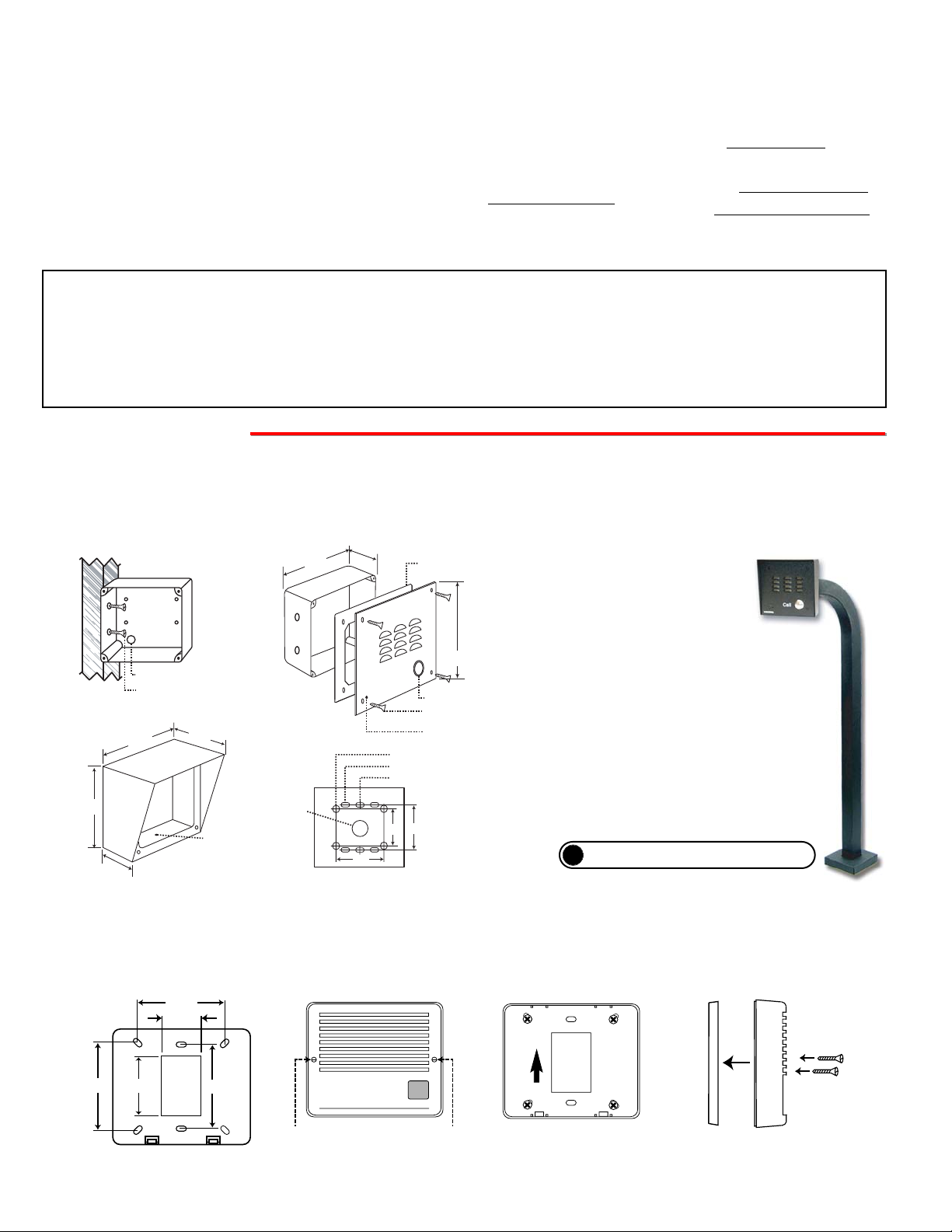
The W-1000 and W-1000-EWP are designed to be flush mounted to the included 4” x 4” x 2” deep plastic rough in box or surface
mounted using optional Viking model VE-5x5. Note: The W-1000/W-1000-EWP will NOT mount to a standard double gang box. The
plastic rough in box (part # 259576) may be purchased separately. Go to www.vikingelectronics.com and click on “Spare Parts”.
A. Mounting the W-1000 and W-1000-EWP
Front View of Optional
VE-5x5 (not included)
2.25”
Condensation
Drain Hole
* 1/8" thick foam gasket (included)
5.14”
5.22”
3.25”
Call
4.0"
Rear View of VE-5x5 (not included)
Push to Call Button
(4) 6-32 X 3/4” black plated stainless steel,
flat head, hexdrive, screws (included)
Condensation Drain Hole
5.0” Typical
W-1000-EWP shown in
VE-5x5 with Viking
Model VE-GNP
Gooseneck Pedestal
(4) 0.38” diameter (for gooseneck mounting)
(4) 0.2 x 0.43 slots for double gang box
(2) 0.2 x 0.43 slots for single gang box
(1) .74" dia
3.0” 3.3”
3.0”
2.1”
Wall Stud
Front View of Plastic
Rough-In Box (included)
Wire knock out
(2) Standard flat head dry wall
(sheet rock) screws (not included)
The optional VE-5x5 Surface Mount Box is designed to be surface
mounted to a single gang box, double gang box or VE-GNP goose-
neck pedestal (right).
?
Need More Information on VE-5x5 or VE-GNP?
Call (715) 386-4345 and select 424.
* Note: Peel off paper liner and
adhere gasket to the back of
the faceplate, centering it over
the four corner mounting holes.
IInnssttaallllaattiioon
n
To open the speaker box, remove the
two screws from the cover.
Mount back panel to a wall, a single
gang box or a 4”x4” junction box with
the arrow pointing up.
3.40”
1.55”
3.30”
2.35”
3.40”
Side view of the
W-2000A/W-2000A-EWP
Attach the cover to the base with
the two included screws as
shown.
Back panel of the
W-2000A/W-2000A-EWP
Front view of the
W-2000A/W-2000A-EWP
B. Mounting the W-2000A and W-2000A-EWP
The W-2000A and W-2000A-EWP are designed to be surface mounted to a single gang box (not included), a standard 4” x 4” electrical junction box (not included), or directly to a wall or flat sided post.
Caution: When warm air comes in contact with cold surfaces, such as outside
walls, it causes condensation. To help
prevent condensation from accumulating inside the W-1000, bring conduit into
the bottom of the unit. If this is not possible, drill a 1/4” diameter hole in the
bottom of the plastic rough-in box.
IF YOU HAVE A PROBLEM WITH A VIKING PRODUCT, PLEASE CONTACT: VIKING TECHNICAL SUPPORT AT (715) 386-8666
Our Technical Support Department is available for assistance Monday 8am-4pm and Tuesday through Friday 8am-5pm central time. So that we can give you better service, before you call please:
1. Know the model number, the serial number and what software version you have (see serial label).
2. Have your Technical Practice in front of you.
3. It is best if you are on site.
WARRANTY
Viking warrants its products to be free from defects in the workmanship or materials, under normal use and service, for a period of one year from the date of purchase from any authorized Viking distributor or 18 months from the date manufactured, which ever is greater. If at any time during the warranty period, the product is deemed defective or malfunctions, return the product to Viking Electronics, Inc., 1531 Industrial Street, Hudson, WI., 54016. Customer must contact Viking's
Technical Support Department at 715-386-8666 to obtain a Return Authorization (R.A.) number.
This warranty does not cover any damage to the product due to lightning, over voltage, under voltage, accident, misuse, abuse, negligence or any damage caused by use of the product by the purchaser or others.
Vikings sole responsibility shall be to repair or replace (at Viking's option) the material within the terms stated above. VIKING SHALL NOT BE LIABLE FOR ANY LOSS OR DAMAGE OF ANY KIND INCLUDING INCIDENTAL OR CONSEQUENTIAL DAMAGES RESULTING DIRECTLY OR INDIRECTLY FROM ANY BREACH OF ANY WARRANTY EXPRESSED OR IMPLIED, OR FOR ANY OTHER FAILURE OF THIS PRODUCT. Some states do not allow the exclusion or limitation of incidental or consequential damages, so this limitation may not apply to you.
THIS WARRANTY IS IN LIEU OF ALL OTHER WARRANTIES, EXPRESSED OR IMPLIED, INCLUDING THE WARRANTIES OF MERCHANTABILITY AND FITNESS FOR A PARTICULAR PURPOSE, WHICH ARE HEREBY EXCLUDED
BEYOND THE ONE YEAR DURATION OF THIS WARRANTY. Some states do not allow limitation on how long an implied warranty lasts, so the above limitation may not apply to you.
RETURNING PRODUCT FOR EXCHANGE
The following procedure is for equipment that has failed out-of-box (within 10 days of purchase):
1. Customer must contact Viking’s Technical Support at 715-386-8666 to determine possible causes for the problem. The
customer MUST be able to step through recommended tests for diagnosis.
2. If the Technical Support Product Specialist determines that the equipment is defective based on the customer's input
and troubleshooting, a Return Authorization (R.A.) number will be issued. This number is valid for fourteen (14)
calendar days from the date of issue.
3. After obtaining the R.A. number, return the approved equipment to your distributor, referencing the R.A. number. Your
distributor will then replace the product over the counter at no charge. The distributor will then return the product to
Viking using the same R.A. number.
4. The distributor will NOT exchange this product without first obtaining the R.A. number from you. If you haven't
followed the steps listed in 1, 2 and 3, be aware that you will have to pay a restocking charge.
RETURNING PRODUCT FOR REPAIR
The following procedure is for equipment that needs repair:
1. Customer must contact Viking's Technical Support Department at 715-386-8666 to obtain a Return Authorization (RA)
number. The customer MUST have a complete description of the problem, with all pertinent information regarding the
defect, such as options set, conditions, symptoms, methods to duplicate problem, frequency of failure, etc.
2. Packing: Return equipment in original box or in proper packing so that damage will not occur while in transit. Static
sensitive equipment such as a circuit board should be in an anti-static bag, sandwiched between foam and individually boxed. All equipment should be wrapped to avoid packing material lodging in or sticking to the equipment. Include
ALL parts of the equipment. C.O.D. or freight collect shipments cannot be accepted. Ship cartons prepaid to:
Viking Electronics, 1531 Industrial Street, Hudson, WI 54016
3. Return shipping address: Be sure to include your return shipping address inside the box. We cannot ship to a PO Box.
4. RA number on carton: In large printing, write the R.A. number on the outside of each carton being returned.
Note: For outdoor applications apply a bead of caulk between back panel and wall.
VIKING©
Call
UP
Page 3

U
SU
T
t
120
C
e
t
C
Power Input
(18V AC max)
O
E
OUT
O
S
SS
CO
CT
OSU
U
CS
6
Multi-Line
e
.
e
C-1000B Controller
S
e
Phone
Important: Do NOT install a W-1000 or W-2000A on a
telephone line without a C-1000B Controller (Fax Back
Document 155).
C. Wiring the W-1000 and W-1000-EWP
O
E
OU
O
S
SS
CO
CT
OSU
U
CS
6
U
d
P
SU
T
t
t
)
120
C
R
e
Output
Multi-Line
Phone
C.O.
e
C-1000B Controller
S
e
Phone
IMPORTANT: Electronic devices are susceptible to lightning and power station electrical surges from both
the AC outlet and the telephone line. It is recommended that a surge protector be installed to protect
against such surges. Contact Panamax at (800) 472-5555 or Electronic Specialists Inc. at (800) 225-4876.
!
Important: Do NOT install a W-1000 or W-2000A on a
telephone line without a C-1000B Controller (Fax Back
Document 155).
D. Wiring the W-2000A and W-2000A-EWP
** Note: To increase surge protection, loosen the PCB mounting screw labeled (as shown above) and fasten a wire with spade terminal (included) from the mounting screw to Earth Ground (grounding rod, water pipe, etc.)
* Note: The gel-filled (water-tight) butt connectors are designed for insulation displacement on 19-26 gauge wire with a maximum insulation diameter of 0.082 inches. Cut off stripped wire ends prior to terminating.
P
S
s
O
ON
Sp
(
)
W-1000/
000
Mi
e
(
W
Rear View of the
W-1000/W-1000-EWP/
W-2000A/W-2000A-EWP
Note: Pots are shown in factory default settings.
PPrrooggrraammmmiinng
g
*** Warning: The power run wire length is limited to 150 ft of 24 AWG wire. Longer power runs will require heavier gauge wire (doubling pairs)
and/or a higher voltage power adapter. Power runs from 150 - 250 ft of 24 AWG wire are possible using a Radio Shack 18VAC adapter (part # 273-
1690). Voltage at the doorbox power input connections must not exceed 18VAC RMS.
**** Note: When wires are routed from above, a “drip loop” is recommended to keep water away from the circuit board.
IMPORTANT: Electronic devices are susceptible to lightning and power station electrical surges from both
the AC outlet and the telephone line. It is recommended that a surge protector be installed to protect
against such surges. Contact Panamax at (800) 472-5555 or Electronic Specialists Inc. at (800) 225-4876.
!
**** Drip Loop
(optional)
**** Drip Loop
(optional)
(Spade connector
included)
Rear View of the W-1000/W-1000-EWP
VIKING
DOOR ENTRY / CCTV VIDEO
C
/ PAGING CONTROLLER
A
V
.8
3
1
R
NTA
W
P
NE
NE LIN
PH
ND
H
LINE
KEYLE
123456789
COM N.O. N.C. - - - -AUX.
SIG GND
SIG GND
SIG GND
VIDEO 1 IN
VIDEO 2 IN
VIDEO OUT
EARTH
C.O. LINE
OUT TO
KEYLESS
GND
INPUT
PHONES
C.C. INPUT
©
ELECTRONI
HUDSON, WI 5401
T
1
X
O
RE INP
B
R
O
L
O
D
CONTACT
OUTPUT
C
LED1
DOOR
BOX 1
MODEL C-1000B
T
U
2
P
X
X
T
O
O
U
B
B
R
O
R
R
R
O
O
O
O
O
O
W
D
D
D
P
14 15 16 17 18 19
10 11 12 13
C
TALK BATTERY
LED2CLED3
OFF ON
DOORBOX
DOOR
N.O. COM N.C.
13VAC PWR
BOX 2
DOOR STRIKE 1
ingle Lin
2
1
E
E
R
IK
IK
O
R
R
O
T
T
D
S
S
ON
1 2 3
N.O. COM N.C.
DOOR STRIKE 2
nused
PABX/K
runk Inpu
or
C.O
Lin
Phon
©
VIKING
DOOR ENTRY / CCTV VIDEO
C
/ PAGING CONTROLLER
A
V
.8
3
1
R
NTA
W
P
T
NE
NE LIN
PH
ND
EYLE
H
LINE
123456789
COM N.O. N.C. - - - -AUX.
SIG GND
SIG GND
SIG GND
VIDEO 1 IN
VIDEO 2 IN
VIDEO OUT
EARTH
C.O. LINE
OUT TO
KEYLESS
GND
INPUT
PHONES
C.C. INPUT
ELECTRONI
HUDSON, WI 5401
T
1
X
O
RE INP
B
R
O
L
O
D
CONTACT
OUTPUT
C
LED1
DOOR
BOX 1
Lin
10 11 12 13
DOORBOX
13VAC PWR
MODEL C-1000B
T
U
2
P
X
X
T
O
O
1
U
B
E
B
R
O
R
R
IK
R
O
O
O
R
O
O
O
T
W
D
D
S
D
P
14 15 16 17 18 19
ON
1 2 3
C
TALK BATTERY
LED2CLED3
OFF ON
N.O. COM N.C.
DOOR
N.O. COM N.C.
DOOR STRIKE 2
BOX 2
DOOR STRIKE 1
ingle Lin
2
E
R
IK
O
R
O
T
D
S
nuse
ABX/K
runk Inpu
* Gel-filled butt
connectors
(EWP only)
or
** Earth
Ground
(optional)
* Gel-filled butt
connectors
(EWP only)
ear View of the W-2000A/W-2000A-EWP
Red
Green
Red
Green
Lin
Outpu
Lin
13.8V A
13.8V AC
Power Inpu
(18V AC max
Gel-filled butt
connectors
(EWP only)
(Spade connector
included)
** Earth
Ground
(optional)
Gel-filled butt
connectors
(EWP only)
V A
V A
W-2
witche
1 2
FF
DI
ON
-1000/W-2000A
A
crophone Volum
see section A)
eaker Volume
see section B
Page 4

Due to the dynamic nature of the product design, the information contained in this document is subject to change without notice. Viking Electronics, and its affiliates and/or
subsidiaries assume no responsibility for errors and omissions contained in this information. Revisions of this document or new editions of it may be issued to incorporate
such changes.
Fax Back Doc 170
ZF301820 Rev D
Printed in the U.S.A.
A. Microphone Volume
?
Need More Information on W-3000?
Call (715) 386-4345 and select 180.
B. Speaker Volume
The SPKR VOL pot can be adjusted to increase or decrease the speaker volume
to the level desired as shown above.
In certain noisy locations (background traffic, machinery or wind), the microphone volume may need to be decreased.
A symptom of this is one-way talk path, in which the distant party cannot be heard over the speaker. A “MIC VOL”
adjustment is provided on the W-1000/2000A for increasing or decreasing the microphone volume. Notes: If the micro-
phone volume is set too high or too low, one-way talk path may occur. For extremely noisy environments, use the W3000 in the “PUSH to TALK” mode.
Sw 2
OFF
OFF
ON
ON
Maximum Rings
2 Ring
3 Rings
10 Rings
30 Rings
Sw 1
OFF
ON
OFF
ON
C. Maximum Number of Rings
The maximum number of rings can be adjusted using the DIP switches. Use the
chart at the right to adjust the maximum number of rings.
OOppeerraattiioon
n
In the idle state, the W-1000 or W-2000A provides 24V DC talk battery. When the “Call” button is pressed, the W-1000 or
W-2000A generates a standard ring cadence (approximately 1 second ON and 3 seconds OFF) that is adjustable to 2, 3,
10 or 30 rings. When the call is answered, ringing will stop automatically and the calling party can converse handsfree (similar to a speakerphone) with the called party. The talk path will be maintained until the called party (inside phone) hangs up.
RReellaatteeddPPrroodduucctts
s
Add Paging and Door Chimes with an SLP-1
The SLP-1 Single Line Paging controller will allow you to page family members or co-workers from
any phone in your home or small office. The pages can be heard over the same speakers that are
installed for music distribution. The SLP-1 connects in series with a single existing phone line. The
unit has a built-in 2 watt amplifier, pre-amp output, music on hold input, intercom features and
selectable loud ringing. The SLP-1 provides an input for a lighted doorbell switch, allowing a door
chime to be heard over existing speakers. Page from several different phone lines by connecting
multiple units. For more information, see DOD# 478.
PPrroodduuccttSSuuppppoorrttLLiinnee......771155..338866..8866666
6
FFaaxxBBaacckkLLiinnee......771155.
.338866..44334455
C-1000B Door Entry Controller
The C-1000B allows single line phones or phone systems to share a phone line with one or two
doorboxes or paging amplifiers. The C-1000B provides two Touch Tone controlled relays to operate door strikes or gate openers and provides doorbox triggered CCTV camera switching.
Doorboxes and paging amplifiers can now be used on single line, residential or home office applications as well as on fully loaded systems, because they are no longer limited to installation on
unused trunk ports. The C-1000B expands the potential installation sites for many peripherals
such as doorboxes and paging amplifiers. For more information, see DOD# 155.
SRC-1 Secure Relay Controller
The SRC-1 enables a standard touch tone phone to securely operate a set of timed relay contacts to control a doorstrike or gate controller at a remote location. The SRC-1 is fully user programmable and uses non-volatile memory. The SRC-1 eliminates the possibility of dialing the
activation code through the entry phone using a hand held touch tone dialer. The SRC-1 is
installed between the entry phone and the secure phone, and will reject touch tones from the
entry phone and only operate the relay if the correct activation code (user programmable) is
given from the secure phone. The SRC-1 also provides up to 32 keyless entry codes to operate
the relay from the entry phone with 1 to 6 digits. This feature can be disabled in programming for
increased security. For more information, see DOD# 409.
 Loading...