

Viking VMTK275 Installation Manual
VIKING RANGE CORPORATION
INSTALLATION
Greenwood, Mississippi 38930 USA
111 Front Street
(662) 455-1200
INSTRUCTIONS
PROFESSIONAL SERIES
CONVECTION MICROWAVE BUILT-IN TRIM KIT
Retain for Future Reference
IMPORTANT - PLEASE READ AND FOLLOW
• Before beginning, please read these instructions completely and carefully.
• Be sure to DISCONNECT THE PLUG of the microwave oven from the electrical outlet before installing the built-in trim kit.
Remove the turntable from the oven cavity.
• Because the kit includes metal parts, caution should be used in handling and installation to avoid the possibility of injury.
• Do not remove permanently affixed labels, warnings, or plates from the product. This may void the warranty.
• Please observe all local and national codes and ordinances.
• The installer should leave these instructions with the consumer who should retain for local inspector’s use and for future
reference.
THIS BUILT-IN TRIM KIT IS DESIGNED FOR USE ONLY WITH VIKING CONVECTION MICROWAVE OVENS SPECIFYING BUILT-IN TRIM KIT VMTK275/276, VMTK305/306 OR VMTK365/366 ON THE RATING LABEL ON THE BOTTOM
FACE PLATE OF THE OVEN CAVITY.
IF YOUR LOWER CONVENTIONAL OVEN IS NOT LISTED IN THE USE AND CARE MANUAL OF THE MICROWAVE
OVEN, THEN DO NOT INSTALL THE MICROWAVE OVEN ABOVE IT OR IN ANY AREA WHERE HEAT AND STEAM
ARE GENERATED; FOR EXAMPLE, NEXT TO OR ABOVE A CONVENTIONAL RANGE.
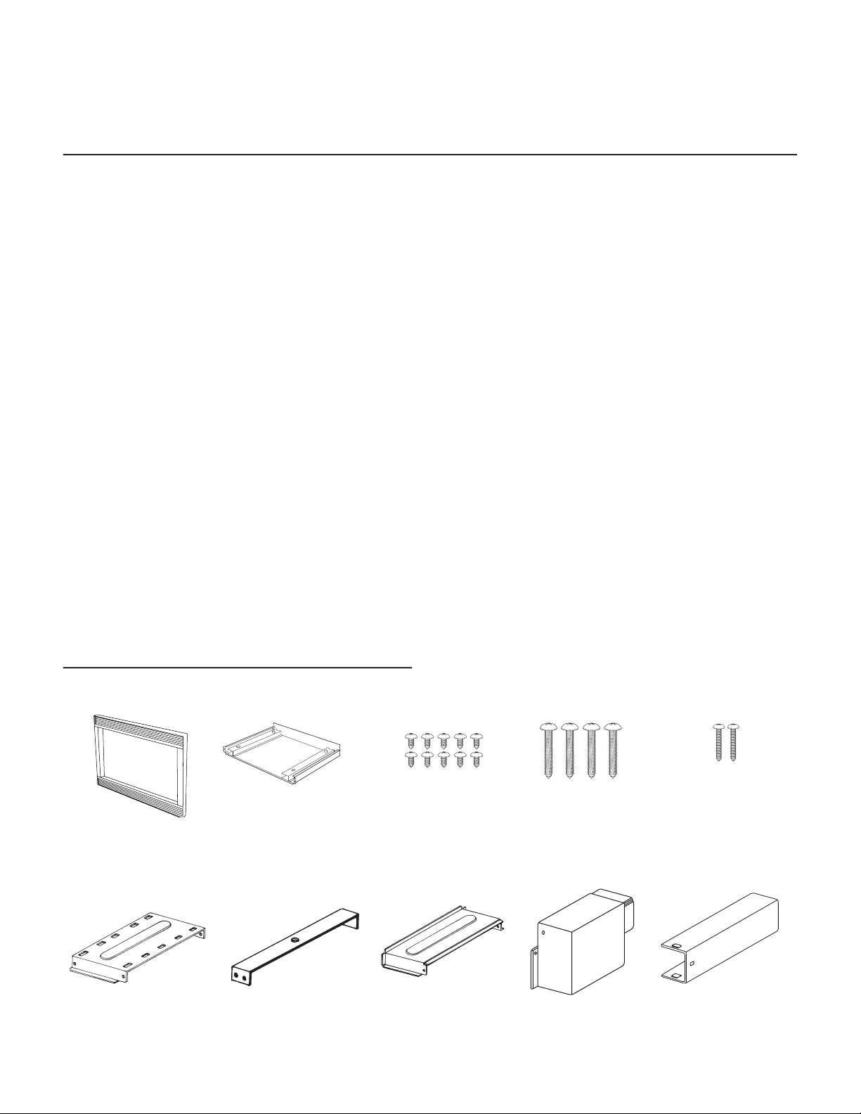
PARTS INCLUDED IN THE VMTK KITS
1) Front Frame Assembly
QTY 1
6) Duct A (1)
QTY 1
2) Bottom Duct Assembly
QTY 1
7) Duct A (2)
QTY 1
3) Screw A (1/2" length)
QTY 10
8) Duct A (3)
QTY 1
4) Screw B (1-3/4" length)
QTY 4
9) Duct B
QTY 1
5) Screw C (1-3/16" length)
QTY 2
10) Duct C
QTY 1
18-1/2"
(47.0 cm)
25" (63.5 cm)
* For 27" kit only
24-1/2"
(62.2 cm)
5"
(12.7 cm)
* 1/4" (0.6 cm)
* 2-1/2"
(6.4 cm)
20-1/8"
(51.1 cm)
11-1/2"
(29.2 cm)
BASIC SPECIFICATIONS
Microwave Oven Built-In Trim Kits
VMOC205 VMTK275/276 VMTK305/306 VMTK365/366
Overall Width 24-5/8” (62.5 cm) 26-1/2” (67.3 cm) 29-1/2” (74.9 cm) 35-1/4” (89.5 cm)
Overall Height from
Bottom
Overall Depth from
Rear
Oven Interior Width
Cutout Width N/A Min. 25” (63.5 cm)
Cutout Height N/A Min. 18-1/2” (46.9 cm)
Cutout Depth N/A Min. 20-1/8” (51.1 cm)
Electrical
Requirements
Max. Amp Usage 1.55 KW
Approx. Shipping Wt. 60 lbs. (27.2 kg) 20.5 lbs. (9.3 kg) 20.5 lbs. (9.3 kg) 22 lbs. (10 kg)
14-7/8” (37.7 cm) 20-3/16”
(50.9 cm)
19” (48.3 cm)
Height
Depth
Overall
16-1/8”
9-5/8”
16-1/8”
1.5 cu. ft.
(40.9 cm)
(24.4 cm)
(40.9 cm)
120VAC/60 Hz (UL)
117VAC/60 Hz (CSA)
13.0 amps (UL)
1.5 KW
13 (CSA)
19-13/16”
(50.1 cm)
20-3/16”
(50.9 cm)
19-13/16”
(50.1 cm)
N/A
N/A
N/A
N/A
20-3/16”
(50.9 cm)
19-13/16”
(50.1 cm)
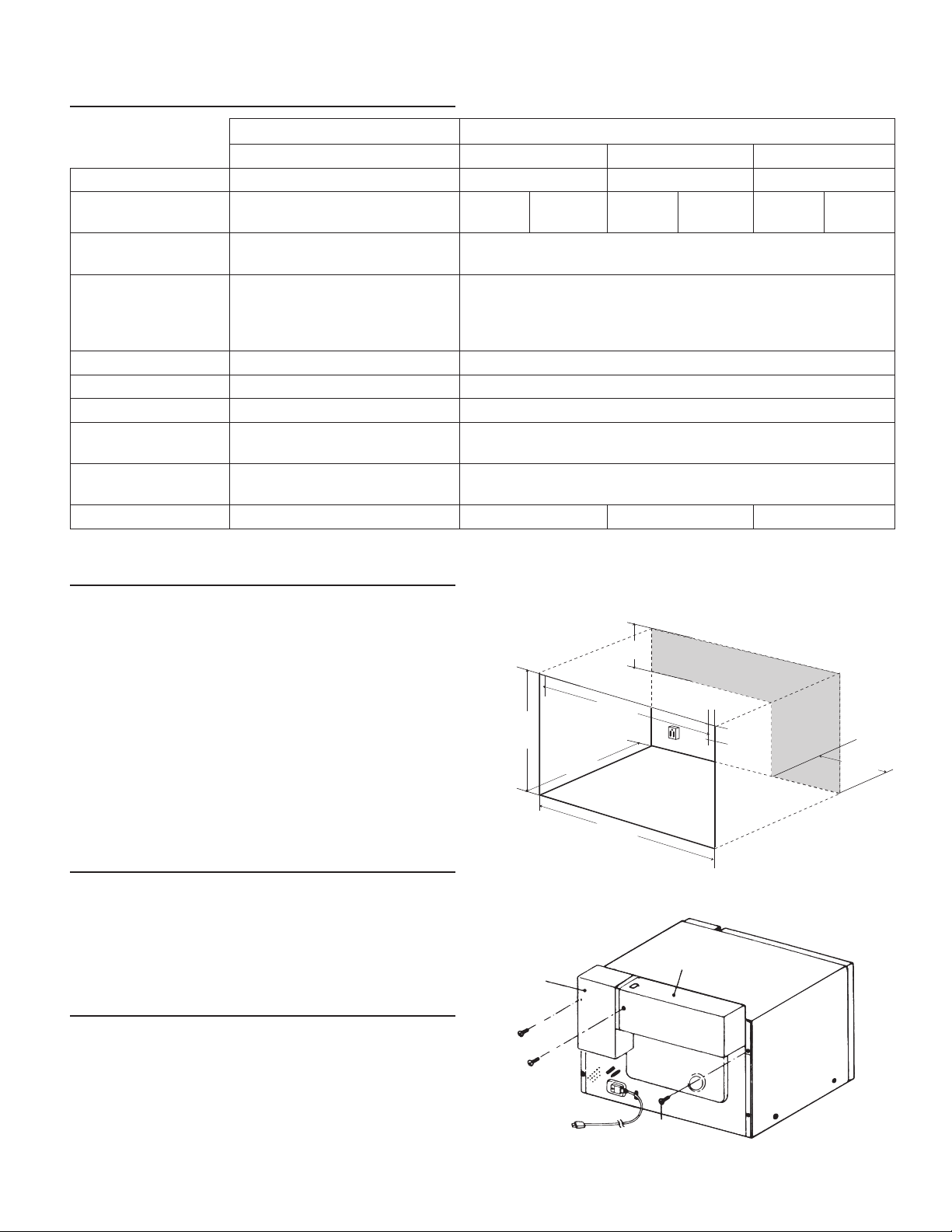
CABINET OR WALL CUTOUT
Provide an opening in the wall or cabinet as indicated in
illustration 1. The depth should be a minimum of 20-1/8"
(51.1 cm). The floor of the opening should be constructed
of plywood strong enough to support the weight of the
oven (about 100 lbs.) and should be level for proper
operation of the oven .
NOTE: While the proper functioning of the oven does not
require that the opening be enclosed (with sides, ceiling
and rear partition), this may be required by local code,
and it is suggested that the local code be checked for
any such requirement.
ELECTRICAL OUTLET LOCATION
Outlet should NOT be in the shaded area as indicated
on illustration 1. At the rear of the opening, provide a
3-pronged, polarized, electrical outlet, 115-120 volt AC,
15 amp or larger.
EXHAUST DUCT ASSEMBLY
Illustration 1
Illustration 2
DUCT C
DUCT B
1. Insert the edge of DUCT (B) into the hold lip of DUCT
(C). Secure together by using a SCREW (A) provided in
the kit. Remove the existing screw (#1) at upper right
rear of the oven and secure DUCT (C) with the screw
(#1) just removed from the oven. Secure DUCT (B) with
SCREW (A) through the duct and into the original screw
hole in the oven. See illustration 2.
SCREW A
SCREW A
#1
2
 Loading...