

Viking VMOC206MJ, VMOC206CB, VMOC206PM, VMOC206VB, VMOC206RR Service Manual
...
SERVICE MANUAL
MICROWAVE OVENS
S11M327MOC206
VMOC206BK
VMOC206WH
VMOC206IB
VMOC206BT
VMOC206SG
MODELS
VMOC206GG
VMOC206BU
VMOC206MS
VMOC206TP
VMOC206SA
Above model is example only
VMOC206AR
VMOC206CH
In the interest of user-safety the oven should be restored to its original condition and only parts identical to those specified should
be used.
WARNING TO SERVICE PERSONNEL: Microwave ovens contain circuitry capable of producing very high voltage and
current. Contact with the following parts may result in a severe, possibly fatal, electrical shock. (Inverter unit that includes
High Voltage Capacitor, High Voltage Power Transformer, High Voltage Rectifier and Heat sink etc., and Magnetron, High
Voltage Harness etc..)
VMOC206LE
VMOC206MJ
VMOC206PM
VMOC206VB
VMOC206CB
VMOC206RR
VMOC206CW
VMOC206OG
VMOC206GM
VMOC206SE
VMOC206PL
VMOC206SS
Page
PRECAUTIONS TO BE OBSERVED BEFORE AND DURING SERVICING TO
AVOID POSSIBLE EXPOSURE TO EXCESSIVE MICROWAVE ENERGY .......................................................... 2
BEFORE SERVICING ............................................................................................................................................ 2
WARNING TO SERVICE PERSONNEL ................................................................................................................. 4
MICROWAVE MEASUREMENT PROCEDURE (Canada) ..................................................................................... 5
MICROWAVE MEASUREMENT PROCEDURE (USA) .......................................................................................... 6
FOREWORD AND WARNING ............................................................................................................................... 7
PRODUCT SPECIFICATIONS ...............................................................................................................................8
GENERAL INFORMATION.................................................................................................................................... 8
OPERATION ......................................................................................................................................................... 10
TROUBLESHOOTING GUIDE ............................................................................................................................. 16
TEST PROCEDURE ............................................................................................................................................ 18
COMPONENT REPLACEMENT AND ADJUSTMENT PROCEDURE.................................................................26
PICTORIAL DIAGRAM ......................................................................................................................................... 33
PARTS LIST ........................................................................................................................................................ 34
PACKING AND ACCESSORIES ..........................................................................................................................39
This document has been published to be used for after
Range Corporation
111 Front St., Greenwood, MS 38930
Tel: (888) 845-4641
TABLE OF CONTENTS
sales service only.
1

PRECAUTIONS TO BE OBSERVED BEFORE AND DURING SERVICING TO AVOID POSSIBLE EXPOSURE TO
EXCESSIVE MICROWAVE ENERGY
(a) Do not operate or allow the oven to be operated with the door open.
(b) Make the following safety checks on all ovens to be serviced before activating the magnetron or other microwave
source, and make repairs as necessary: (1) interlock operation, (2) proper door closing, (3) seal and sealing
surfaces (arcing, wear, and other damage), (4) damage to or loosening of hinges and latches, (5) evidence of
dropping or abuse.
(c) Before turning on microwave power for any service test or inspection within the microwave generating compart-
ments, check the magnetron, wave guide or transmission line, and cavity for proper alignment, integrity, and
connections.
(d) Any defective or misadjusted components in the interlock, monitor, door seal, and microwave generation and
transmission systems shall be repaired, replaced, or adjusted by procedures described in this manual before
the oven is released to the owner.
(e) A microwave leakage check to verify compliance with the Federal Performance Standard should be performed
on each oven prior to release to the owner.
BEFORE SERVICING
Before servicing an operative unit, perform a microwave emission check as per the Microwave Measurement Procedure outlined in this service manual.
If microwave emissions level is in excess of the specified limit, contact Viking Service immediately @
1-888-845-4641.
If the unit operates with the door open, service person should (1) tell the user not to operate the oven and
(2) contact VIKING, plus the Department Of Health, Canada and/or the Food and Drug Administration's
Center for Devices and Radiological Health immediately.
Service personnel should inform VIKING of any certified unit found with emissions in excess of 4mW/
cm2. The owner of the unit should be instructed not to use the unit until the oven has been brought into
compliance.
DANGER CAUTION
HIGH VOLTAGE
Do not energize a microwave oven with the outer case cabinet removed, because a microwave oven generates High Voltage in the circuit.
If you intend to operate the oven employing the high frequency switching power converter circuit, you should
take special precautions to avoid an electrical shock hazard.
The high voltage transformer, high voltage capacitor and high voltage diode have energized high voltage
potential approx. 8 KV.
The aluminium heat sink is connected to the switching power transistor Collector pole, and has an energized
high voltage potential approx. 650V peak.
DO NOT ACCESS THE HIGH VOLTAGE TRANSFORMER, HIGH VOLTAGE CAPACITOR, HIGH VOLTAGE DIODE AND HEAT SINK WHEN THE POWER SUPPLY IS CONNECTED TO AN ELECTRICAL
OUTLET.
2

Notes
3
WARNING TO SERVICE PERSONNEL
Microwave ovens contain circuitry capable of producing very high voltage and current, contact with
following parts
fatal, electrical shock.
(Example)
High Voltage Capacitor, High Voltage Power
Transformer, Magnetron, High Voltage Rectifier
Assembly, High Voltage Harness etc..
Read the Service Manual carefully and follow all
instructions.
may result in a severe, possibly
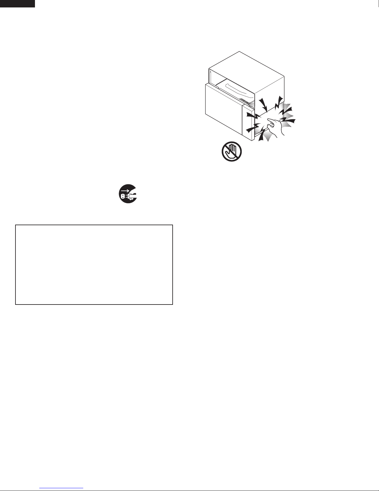
Don't Touch !
Danger High Voltage
Before Servicing
1. Disconnect the power supply cord , and then
remove outer case.
2. Open the door and block it open.
3. Discharge high voltage capacitor.
WARNING: RISK OF ELECTRIC SHOCK.
DISCHARGE THE HIGH-VOLTAGE
CAPACITOR BEFORE SERVICING.
The high-voltage capacitor remains charged about 60
seconds after the oven has been switched off. Wait for
60 seconds and then short-circuit the connection of the
high-voltage capacitor (that is the connecting lead of the
high-voltage rectifier) against the chassis with the use of
an insulated screwdriver.
Whenever troubleshooting is performed the power supply
must be disconnected. It may in, some cases, be necessary
to connect the power supply after the outer case has been
removed, in this event,
1. Disconnect the power supply cord, and then remove
outer case.
2. Open the door and block it open.
3. Discharge high voltage capacitor.
4. Disconnect the leads to the primary of the power
transformer.
5. Ensure that the leads remain isolated from other
components and oven chassis by using insulation
tape.
6. After that procedure, reconnect the power supply cord.
When the testing is completed,
1. Disconnect the power supply cord, and then remove
outer case.
2. Open the door and block it open.
3. Discharge high voltage capacitor.
4. Reconnect the leads to the primary of the power
transformer.
5. Reinstall the outer case (cabinet).
6. Reconnect the power supply cord after the outer case
is installed.
7. Run the oven and check all functions.
After repairing
1. Reconnect all leads removed from components during
testing.
2. Reinstall the outer case (cabinet).
3. Reconnect the power supply cord after the outer case
is installed.
4. Run the oven and check all functions.
Microwave ovens should not be run empty. To test for the
presence of microwave energy within a cavity, place a cup
of cold water on the oven turntable, close the door and set
the power to HIGH and set the microwave timer for two (2)
minutes. When the two minutes has elapsed (timer at zero)
carefully check that the water is now hot. If the water remains
cold carry out Before Servicing procedure and re-examine
the connections to the component being tested.
When all service work is completed and the oven is fully
assembled, the microwave power output should be checked
and a microwave leakage test should be carried out.
4

MICROWAVE MEASUREMENT PROCEDURE (CANADA)
After adjustment of the door switches are completed individually or collectively, switch test and microwave leakage test
must be performed with survey instrument and test result must be confirmed to meet the requirement of the performance
standard
for microwave ovens as undermentioned.
A. Requirements:
Every microwave oven shall function in such a manner that when the oven is fully assembled and operating with its
service
controls and user controls adjusted to yield the maximum output, the leakage radiation, at all points at least 5 cm. from
the
external surface of the oven, does not exceed:
1) 1.0mW/cm2 with the test load of 275 ± 15 ml of water at an initial temperature 20 ±5oC.
2) 5.0mW/cm
20±5oC.
3) 5.0mW/cm
2
when the outer enclosure is removed with a test load of 275 ± 15 ml of water at an initial temperature
2
without a test load.
B. Preparation for testing:
Before beginning the actual measurement of leakage, proceed as follows:
1) Make sure that the actual instrument is operating normally as specified in its instruction booklet.
Important:
Survey instruments that comply with the requirement for instrumentation as prescribed by CSA and NHW performance standard for microwave ovens must be used for testing recommended instruments are , NARDA 8100 and NARDA 8200.
2) Place the oven tray in the oven cavity.
3) Place the load of 275±15 ml of tap water initially at 20±5oC in the center of the oven cavity.
The water container shall be a low form of 600 ml beaker with an inside diameter of approx. 8.5 cm (3-1/2 in.) and made
of an electrically nonconductive material such as glass or plastic.
The placing of this standard load in the oven is important not only to protect the oven, but also to insure that any leakage
is measured accurately.
4) Set the cooking control on Full Power Cooking Mode, Close the door and select a cook cycle of several minutes. If the
water begins to boil before the survey is completed, replace it with 275 ml of cool water.
C. Leakage test with enclosure installed :
1) Grasp the probe of the survey instrument and hold it perpendicular to the gap between the door and the body of the
oven.
2) Move the probe slowly, not faster than 2.5 cm/sec. along the gap, watching for the maximum indication on the meter.
3) Check for leakage at the door screen, sheet metal seams and other accessible positions where the continuity of the
metal has been breached (eg., around the switches, indicator, and vents).
While testing for leakage around the door pull the door away from the front of the oven as far as is permitted by the
closed latch assembly.
4) Measure carefully at the point of highest leakage and make sure that the highest leakage is no greater than 4mW/cm2,
and that the secondary interlock switch does turn the oven OFF before any door movement.
C. Leakage test without enclosure:
1) Remove the enclosure (cabinet).
2) Grasp the probe of the survey instrument and hold it perpendicular to all mechanical and electric parts of the oven that
is accessible to the user of the oven including, but not limited to, the waveguide, cavity seams, magnetron gap between
the door and the body of the oven.
3) Move the probe slowly, not faster than 2.5 cm/sec. along the gap, watching for the maximum indication on the meter.
4) Measure carefully at the point of highest leakage and make sure that the highest leakage is under 5mW/cm2.
CAUTION: Special attention should be given to avoid electrical shock because HIGH VOLTAGE is generated during this
test
No Load test
1) Operate the oven without a load and measure the leakage by the same method as the above test procedure "
Leakage test with enclosure installed"
2. Make sure that the highest leakage should not exceed 5mW/cm2.
NOTE: After servicing, record data on service invoice and microwave leakage report.
5

MICROWAVE MEASUREMENT PROCEDURE (USA)
A. Requirements:
1) Microwave leakage limit (Power density limit): The power density of microwave radiation emitted by a microwave
oven should not exceed 1mW/cm2 at any point 5cm or more from the external surface of the oven, measured prior to
acquisition by a purchaser, and thereafter (through the useful life of the oven), 5 mW/cm2 at any point 5cm or more
from the external surface of the oven.
2) Safety interlock switches:
Primary interlock relay switch shall prevent microwave radiation emission in excess of the requirement as above
mentioned. Secondary interlock relay and door sensing switch shall prevent microwave radiation emission in excess
of
5 mW/cm2 at any point 5cm or more from the external surface of the oven.
B. Preparation for testing:
Before beginning the actual measurement of leakage, proceed as follows:
1) Make sure that the actual instrument is operating normally as specified in its instruction booklet.
Important:
Survey instruments that comply with the requirement for instrumentation as prescribed by the performance standard for
microwave ovens, 21 CFR 1030.10(c)(3)(i), must be used for testing.
2) Place the oven tray in the oven cavity.
3) Place the load of 275±15 ml (9.8 oz) of tap water initially at 20±5
The water container shall be a low form of 600 ml (20 oz) beaker with an inside diameter of approx. 8.5 cm (3-1/2 in.)
and made of an electrically nonconductive material such as glass or plastic.
The placing of this standard load in the oven is important not only to protect the oven, but also to insure that any leakage
is measured accurately.
4) Set the cooking control on Full Power Cooking Mode.
5) Close the door and select a cook cycle of several minutes. If the water begins to boil before the survey is completed,
replace it with 275 ml of cool water.
O
C (68OF) in the center of the oven cavity.
C. Leakage test:
Closed-door leakage test (microwave measurement):
1) Grasp the probe of the survey instrument and hold it perpendicular to the gap between the door and the body of the
oven.
2) Move the probe slowly, not faster than 1 in./sec. (2.5 cm/sec.) along the gap, watching for the maximum indication on
the meter.
3) Check for leakage at the door screen, sheet metal seams and other accessible positions where the continuity of the
metal has been breached (eg., around the switches, indicator, and vents).
While testing for leakage around the door, pull the door away from the front of the oven as far as is permitted by the
closed latch assembly.
4) Measure carefully at the point of highest leakage and make sure that the highest leakage is no greater than 4mW/cm2,
and that the primary interlock switch/secondary interlock relay does turn the oven OFF before any door movement.
NOTE: After servicing, record data on service invoice and microwave leakage report.
6

SERVICE MANUAL
VIKING RANGE CORPORATION
MICROWAVE OVENS
VMOC206BK
This Manual has been prepared to provide Viking Service Personnel with
Operation and Service Information for the Viking Microwave Ovens.
It is recommended that service personnel carefully study the entire text of
this manual so that they will be qualified to render satisfactory customer
service.
Check the interlock switches and the door seal carefully. Special attention
should be given to avoid electrical shock and microwave radiation hazard.
Never operate the oven until the following points are ensured:
(A) The door is tightly closed.
(B) The door brackets and hinges are not defective.
(C) The door packing is not damaged.
(D) The door is not deformed or warped.
(E) There is no other visible damage with the oven.
VMOC206WH
VMOC206IB
VMOC206BT
VMOC206SG
VMOC206GG
VMOC206BU
VMOC206MS
VMOC206TP
VMOC206SA
VMOC206AR
VMOC206CH
FOREWORD
WARNING
VMOC206LE
VMOC206MJ
VMOC206PM
VMOC206VB
VMOC206CB
VMOC206RR
VMOC206CW
VMOC206OG
VMOC206GM
VMOC206SE
VMOC206PL
VMOC206SS
PRODUCT DESCRIPTION
GENERAL INFORMATION
OPERATION
TROUBLESHOOTING GUIDE AND
TEST PROCEDURE
COMPONENT REPLACEMENT
AND ADJUSTMENT PROCEDURE
WIRING DIAGRAM
PARTS LIST
Servicing and repair work must be carried out only by trained service
personnel.
DANGER
Certain initial parts are intentionally not grounded and present
a risk of electrical shock only during servicing. Service personnel - Do not contact the following parts while the appliance is
energized;
High Voltage Capacitor, Power Transformer, Magnetron, High Voltage Rectifier Assembly, High Voltage Harness;
If provided, Vent Hood, Fan assembly, Cooling Fan Motor.
All the parts marked “*” on parts list are used at voltages more than
250V.
Removal of the outer wrap gives access to voltage above 250V.
All the parts marked “∆” on parts list may cause undue microwave
exposure, by themselves, or when they are damaged, loosened or
removed.
VIKING RANGE CORPORATION
111 Front St., Greenwood, MS 38930
Tel: (888) 845-4641
7
SPECIFICATION
ITEM DESCRIPTION
Power Requirements 120 Volts (USA), 117 Volts (Canadian)
13.0 Amperes (Microwave) / 13.0 Amperes (Convection)
60 Hertz / Single phase, 3 wire grounded
Power Output 900 watts (IEC 705 Test Procedure)
Operating frequency of 2450MHz
Convection Power Output 1450 Watts
Case Dimensions Width 24-5/8" Height 14-7/8" Depth 19-1/8"
Cooking Cavity Dimensions
(1.5 Cubic Feet ) (Stainless Steel) Width 16-1/8" Height 9-5/8" Depth 16-1/8"
Control Complement Touch Control System
Timer (0 - 99 min. 99 seconds)
Microwave Power for Variable Cooking
Repetition Rate;
P-HI ........................................... Full power throughout the cooking time
P-90 .............................................................. approx. 90% of Full Power
P-80 .............................................................. approx. 80% of Full Power
P-70 .............................................................. approx. 70% of Full Power
P-60 .............................................................. approx. 60% of Full Power
P-50 .............................................................. approx. 50% of Full Power
P-40 ............................................................... approx. 40% of Full Power
P-30 .............................................................. approx. 30% of Full Power
P-20 .............................................................. approx. 20% of Full Power
P-10 ............................................................... approx. 10% of Full Power
P-0 .............................................. No power throughout the cooking time
Convection Temperature for Variable Cooking
CONVECTION ............................................... 100 - 450
LOW MIX. BAKE ............................... 350οF with 10% microwave power
HIGH MIX. ROAST ............................ 300οF with 30% microwave power
SLOW COOK .......................................... 300οF for 4 hours (no preheat)
BROIL ............................................................................450οF (preheat)
Help pad, Reheat pad, Add-A-Minute pad, Popcorn pad
Defrost pad, Sensor Cook pad, Convec Broil pad
Convec Roast pad, Convec Bake pad, Convec pad
Broil pad, Slow Cook pad, Preheat pad.
Number and temperature selection pads, Timer pad, Clock pad
Stop/Clear pad, Power Level pad, Start / Touch On pad
Oven Cavity Light Yes
Safety Standard UL Listed FCC Authorized
DHHS Rules, CFR, Title 21, Chapter 1, Subchapter J
Canadian Standards Association.
Health CANADA, Industry CANADA.
ο
F Temp. control
GENERAL INFORMATION
GROUNDING INSTRUCTIONS
This oven is equipped with a three prong grounding plug. It must be plugged into a wall receptacle that is properly installed
and grounded.
In the event of an electrical short circuit, grounding reduces the risk of electric shock by providing an escape wire for the
electric current.
WARNING: Improper use of the grounding plug can result in a risk of electric shock.
8
Electrical Requirements
The electrical requirements are a 115 -120 volt 60 Hz, AC only,
15 or more amp. fused electrical supply. It is recommended that a separate circuit serving only this appliance be provided. When installing this
3-Pronged Plug
Grounded
Receptacle Box
appliance, observe all applicable codes and ordinances.
A short power-supply cord is provided to reduce risks of becoming
entangled in or tripping over a longer cord.
Where a two-pronged wall-receptacle is encountered, it is the personal
responsibility and obligation of the customer to contact a qualified electrician and have it replaced with a properly grounded three-pronged wall
Grounding Pin
receptacle or have a grounding adapter properly grounded and polarized. If an extension cord must be used, it should be a 3-wire, 15 amp.
or more cord. Do not drape over a countertop or table where it can be
3-Pronged Receptacle
pulled on by children or tripped over accidentally.
CAUTION: DO NOT UNDER ANY CIRCUMSTANCES CUT OR REMOVE THE ROUND GROUNDING PRONG FROM
THIS PLUG.
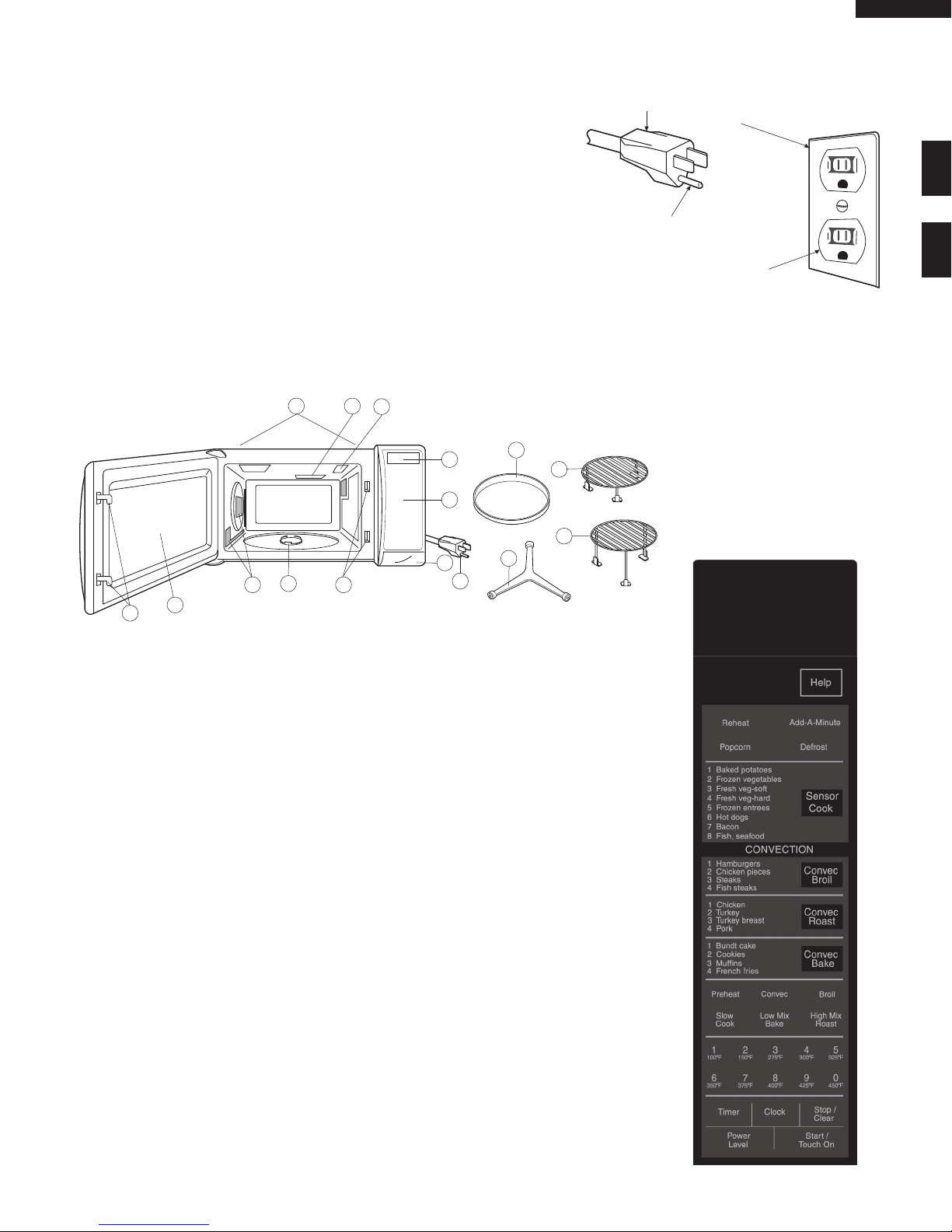
OVEN DIAGRAM
1
14
11 6
2
6
1. Ventilation openings. (Rear side)
2. Oven door with see-through window.
3. Oven lamp.
4. Turntable support.
5. Removable turntable.
The turntable w ill rotate clockwise or
counterclockwise.
6. Safety door latches.
The oven will not operate unless the door is
securely closed.
7. Wave guide cover.
7
3
10
9
8
15
8. Door open button.
9. Auto-Touch control panel.
10. Lighted digital display.
11. Convection air openings.
12. Removable low rack. (Broiling trivet)
13. Removable low rack. (Baking rack)
14. Turntable motor shaft.
15. Power supply cord.
5
12
4
13
TOUCH CONTROL PANEL
9

OPERATION
DESCRIPTION OF OPERATING SEQUENCE
The following is a description of component functions during oven operation.
OFF CONDITION
Closing the door activates the door sensing switch and
secondary interlock switch. (In this condition, the monitor
switch contacts are opened.)
When oven is plugged in, 117 volts A.C. is supplied to the
control unit. (Figure O-1).
1. The display will show "WELCOME, PRESS CLEAR".
To set any program or set the clock, you must first touch
the STOP/CLEAR pad. The display will clear, and " : "
will appear.
NOTE: When the door is opened, the oven lamp comes
on.
2. A signal is input to the control unit, energizing the coil
of shut-off relay (RY-4). RY4 contacts close, completing
a circuit to the damper motor. The damper motor now
operates moving the damper to the open position, thereby
closing the contacts of the damper switch inputs a signal
to the control unit. The coil of relay RY-4 is de-energized,
opening its contacts, thereby turning off the damper
motor.
COOKING CONDITION
Program desired cooking time Variable Cooking Control
by touching the NUMBER pads and the power level pad.
When the START pad is touched, the following operations
occur:
1. The contacts of relays are closed and components
connected to the relays are turned on as follows.
(For details, refer to Figure O-2)
RELAY CONNECTED COMPONENTS
RY-1 Oven lamp/Turntable motor
RY-2 Power transformer
RY-3 Heating element
RY-4 Damper motor
RY-5 Convevtion motor
RY-6 Fan motor
2. 117 volts A.C. is supplied to the primary winding of the
power transformer and is converted to about 3 volts A.C.
output on the filament winding, and approximately 2360
volts A.C. on the high voltage winding.
3. The filament winding voltage heats the magnetron
filament and the H.V. winding voltage is sent to a voltage
doubler circuit.
4. The microwave energy produced by the magnetron is
channelled through the waveguide into the cavity feedbox, and then into the cavity where the food is placed
to be cooked.
5. Upon completion of the cooking time, the power
transformer, oven lamp, etc. are turned off, and the
generation of microwave energy is stopped. The oven
will revert to the OFF condition.
6. When the door is opened during a cook cycle, third
door switch, monitor switch, door sensing switch, the
secondary interlock relay and the primary interlock switch
are activated with the following results. The circuits to
the turntable motor, the cooling fan motor, and the high
voltage components are de-energized, the oven lamp
remains on, and the digital read-out displays the time
still remaining in the cook cycle when the door was
opened.
7. The monitor switch is electrically monitoring the operation
of the relay (RY1) and the primary interlock switch and
is mechanically associated with the door so that it will
function in the following sequence.
(1) When the door opens from a closed position, the door
sensing switch and the primary interlock switch open
their contacts, and then the monitor switch contacts
close and then the third door switch contacts open.
(2) When the door is closed from the open position, the
monitor switch contacts open and the third door switch
contacts close first, and then the contacts of the primary
interlock switch and the door sensing switch close.
If the relay (RY1) and the primary interlock switch fail with
their contacts closed when the door is opened, the closing of
the monitor switch contacts will form a short circuit through
the C/T fuse, the relay (RY1) and the primary interlock switch,
causing the C/T fuse to blow.
POWER LEVEL P-0 TO P-90 COOKING
When Variable Cooking Power is programmed, the 117
volts A.C. is supplied to the power transformer intermittently
through the contacts of relay (RY-2). RY-2 is operated by the
control unit within an varying time base. Microwave power
operation is as follows:
VARI-MODE ON TIME OFF TIME
Power 10(P-HI) 32 sec. 0 sec.
(100% power)
Power 9(P-90) 30 sec. 2 sec.
(approx. 90% power)
Power 8(P-80) 26 sec. 6 sec.
(approx. 80% power)
Power 7(P-70) 24 sec. 8 sec.
(approx. 70% power)
Power 6(P-60) 22 sec. 10 sec.
(approx. 60% power)
Power 5(P-50) 18 sec. 14 sec.
(approx. 50% power)
Power 4(P-40) 16 sec. 16 sec.
(approx. 40% power)
Power 3(P-30) 12 sec. 20 sec.
(approx. 30% power)
Power 2(P-20) 8 sec. 24 sec.
(approx. 20% power)
Power 1(P-10) 6 sec. 26 sec.
(approx. 10% power)
Power 0(P-0) 0 sec. 32 sec.
(0% power)
Note: The ON/OFF time ratio does not correspond with the
percentage of microwave power, because approx. 2
10

CONVECTION COOKING CONDITION
PREHEATING CONDITION
Program desired convection temperature by touching the
CONVECTION pad and the Temperature pad.
When the START pad is touched, the following operations
occur:
1. The coil of shut-off relays (RY1, RY3,RY5 and RY6) are
energized, the oven lamp, cooling fan motor, turntable
motor and convection motor are turned on.
2. The coil of relay (RY4) is energized by the control unit.
The damper is moved to the closed position, opening
the damper switch contacts. The opening of the damper
switch contacts sends a signal to the LSI on the control
unit de-energizing the relay (RY4) and opening the circuit
to the damper motor.
3. The coil of heater relay (RY3) is energized by the control
unit and the main supply voltage is applied to the heating
element.
4. When the oven temperature reaches the selected preheat
temperature, the following operations occur:
4-1 The heater relay is de-energized by the control unit
temperature circuit and thermistor, opening the circuit
to the heating element.
4-2. The oven will continue to function for 30 minutes,
turning the heater on and off, as needed to maintain
the selected preheat temperature. The oven will
shut-down completely after 30 minutes
CONVECTION COOKING CONDITION
When the preheat temperature is reached, a beep signal
will sound indicating that the holding temperature has been
reached in the oven cavity. Open the door and place the
food to be cooked in the oven.
Touch the CONVEC pad first and then touch the Temperature pad. And program desired cooking time by touching
the Number pads.
When the START pad is touched, the following operations
occur:
1. The numbers on the digital read-out start to count down
to zero.
2. The oven lamp, turntable motor, cooling fan motor and
convection motor are energized.
3. Heater relay (RY3) is energized (if the cavity temperature
is lower than the selected temperature) and the main
supply voltage is applied to the heating element to return
to the selected cooking temperature.
4. Upon completion of the cooking time, the audible signal
will sound, and oven lamp, turntable motor, cooling fan
motor and convection motor are de-energized. At the
end of the convection cycle, if the cavity air temperature
is above 275οF, the circuit to RY6 will be maintained (by
the thermistor circuit) to continue operation of the cooling
fan motor until the temperature drops below 245οF, at
which time the relay will be de-energized, turning off the
fan motor. Relay RY5 will however, open as soon as the
convection cycle has ended, turning off the convection
fan motor.
5. At the end of the convection cook cycle, shut-off relay
(RY4) is energized turning on the damper motor. The
damper is returned to the open position, closing the
damper switch contacts which send a signal to the control
unit, de-energizing shut-off relay (RY4).
AUTOMATIC MIX COOKING CONDITION
Touch the HIGH MIX/ROAST or the LOW MIX/BAKE pad
first. And then program desired cooking time by touching
the Number pads. The LOW MIX/BAKE pad is preprogrammed for 350
ο
F with 10% microwave power, while the
HIGH MIX/ROAST pad is preprogrammed for 300οF with
30% microwave power. When the START pad is touched,
the following operations occur:
1. The numbers on the digital read-out start to count down
to zero.
2. The shut-off relays (RY1,RY2,RY3,RY5 and RY6) are
energized, turning on the oven lamp, turntable motor,
cooling fan motor and convection fan motor.
3. The shut-off relay (RY4) is energized.
The damper door is closed from the open position.
4. The heater relay (RY3) is energized, applying the main
supply voltage to the heating element.
5. Now, the oven is in the convection cooking condition.
6. When the oven temperature reaches the selected
temperature, the following operations occur:
6-1. The power supply voltage is alternated to the heating
element and power transformer.
6-2. The heating element operates through the heater
relay (RY3) contacts and the power transformer
operates through the primary interlock relay (RY2)
contacts.
6-3. These are operated by the control unit to supply
alternately within a 32 second time base, convection
heat and microwave energy.
The relationship between the convection and microwave
power operations are as follows.
Note: The ON and OFF time ratio does not correspond
with the percentage of microwave power, because
approx. 2 seconds are needed for heating of the
magnetron filament.
26 SEC.6 SEC.
(MICRO.)
(CONVEC.)
(MICRO.)
(CONVEC.)
ON
OFF
LOW MIX
BAKE
12 SEC. 20 SEC.
ON
OFF
ON
OFF
32 SEC.
HIGH MIX
ROAST
MICROWAVE POWER
= APPROX. 10%
CONVECTION
TEMPERATUE
= 350°F (180°C)
MICROWAVE POWER
= APPROX. 30%
CONVECTION
TEMPERATUE
Note: During alternate Microwave/Convection operation,
the convection heater is energized only if the cavity
temperature drops below the set temperature.
SENSOR COOKING CONDITION
Using the SENSOR COOK function, the foods are cooked
without figuring time, power level or quantity. When the oven
senses enough steam from the food, it relays the information to its microprocessor which will calculate the remaining
cooking time and power level needed for best results.
When the food is cooked, water vapor is developed.
The sensor “senses” the vapor and its resistance increases
11
= 300°F
gradually. When the resistance reaches the value set ac-
MICROWAVE
AH SENSOR
MICROWAVE
CONVECTION
MOTOR
THERMISTOR
Sensing
Voltage
ON
OFF
ON
OFF
ON
OFF
0 2 3 24 30 32 (sec.) 64 (sec.)
3 sec.
Sensing the voltage across temperature measurement circuit.
6 sec.
cording to the menu, supplementary cooking is started.
The time of supplementary cooking is determined by experiment with each food category and inputted into the LSI.
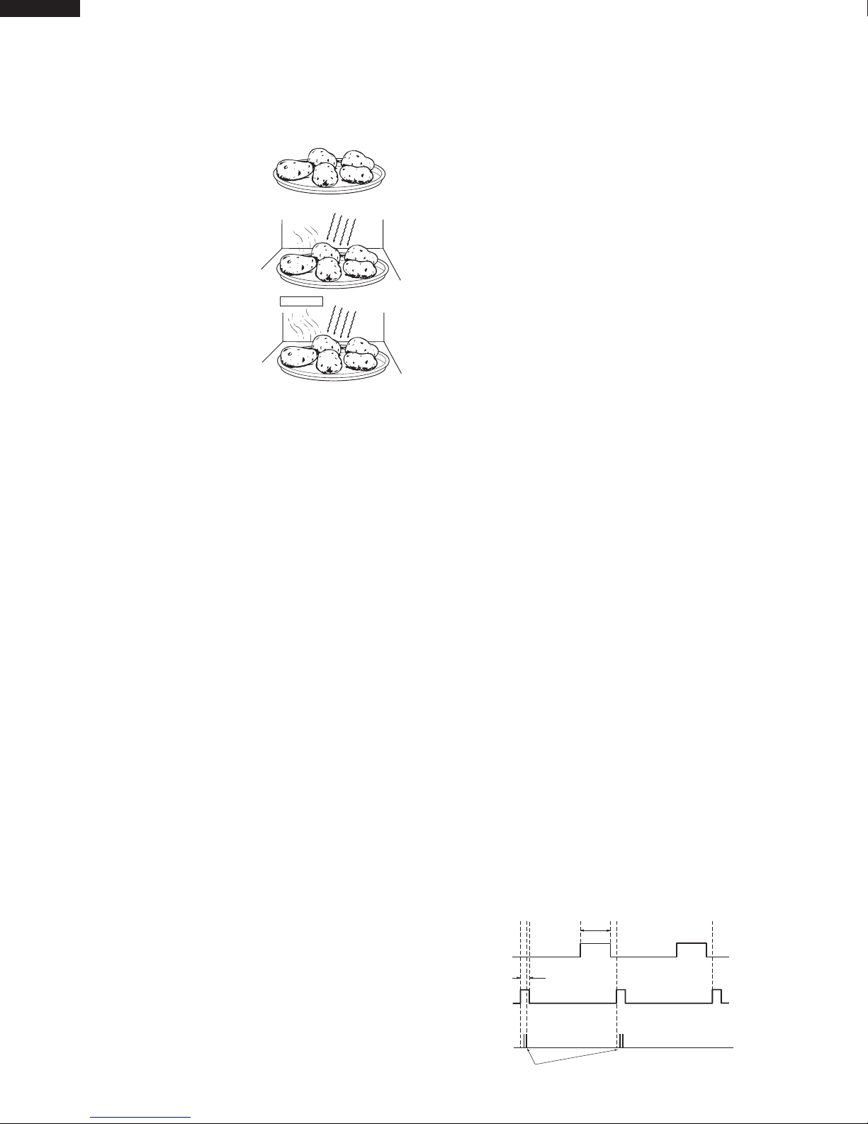
An example of how sensor works:
1. P o t a t o e s a t r o o m
temperature.
Vapor is emitted very slowly.
2. Heat potatoes. Moisture and
humidity is emitted rapidly.
You can smell the aroma as
it cooks.
3. Sensor d e t ects mo isture
and humidity and calculates
cooking time and variable
power.
Cooking Sequence.
1. Touch SENSOR COOK pad.
NOTE: The oven should not be operated on SENSOR
COOK immediately after plugging in the unit. Wait
two minutes before cooking on SENSOR COOK.
2. Select desired Sensor setting.
3. Touch START pad.
The coil of shut-off relay (RY1, RY6) is energized, the
oven lamp and cooling fan motor are turned on, but the
power transformer is not turned on.
4. After about 16 seconds, the cook relay (RY-2) is energized.
The power transformer is turned on, microwave energy
is produced and first stage is started. The 16 seconds
is the cooling time required to remove any vapor from
the oven cavity and sensor.
NOTE: During this first stage, do not open the door or touch
STOP/CLEAR pad.
5. When the sensor detects the vapor emitted from the
food, the display switches over to the remaining cooking
time and the timer counts down to zero. At this time, the
door may be opened to stir food, turn it or season, etc.
6. When the timer reaches zero, an audible signal sounds.
The shut-off relay and cook relay are de-energized and
the power transformer, oven lamp, etc. are turned off.
7. Opening the door or touching the STOP/CLEAR pad, the
time of day will reappear on the display and the oven will
revert to an OFF condition.
COMPU BROIL/ COMPU ROAST/ COMPU BAKE
COMPU BROIL/ ROAST/ BAKE will automatically compute
the oven temperature, microwave power and cooking time
for baking, roasting and broiling. Set the desired program
by touching the COMPU BROIL/ ROAST/ BAKE pad, and
number pad. Enter the weight by touching the Number pads.
When the START pad is touched, the following operations
occur:
1. The COOK indicator will light and the Convection Fan
Symbol will rotate.
2. The cooking time will appear on the display and start
3. The shut-off relays (RY1, RY5 and RY6) are energized,
4. Now, the oven is in the convection cooking mode.
counting down to zero. The cooking time is adjusted
automatically according to the weight of the food.
turning on the oven lamp, turntable motor, cooling fan
motor and convection motor. The power supply voltage
is applied to the heating element.
5. When the oven temperature has reached the programmed
convection temperature, the oven goes into the
programmed cooking mode.
6. At the end of the COMPU BROIL/ ROAST/ BAKE cycle,
the damper is returned to the open position and the oven
will go to the off condition. The cooling fan will remain
on until the oven has cooled.
COMPU DEFROST COOKING
The COMPU DEFROST key is a special function key to defrost meats and poultry faster and better. COMPU DEFROST
automatically defrosts roast beef, etc.. When the COMPU
DEFROST is selected and the food weight is entered by
using the COMPU DEFROST pad, the oven will cook according to the special cooking sequence.
FIRE SENSING FEATURE (MICROWAVE MODE)
This model incorporates a sensing feature which will stop
the oven's operation if there is a fire in the oven cavity during microwave cooking.
This is accomplished by the LSI repeatedly measuring
the voltage across the temperature measurement circuit
(thermistor) during it's 32-seconds time base comparing the
obtained voltage measurements. If the most recent voltage measured is 300mV greater than the previous voltage
measured, the LSI judges it as a fire in the oven cavity and
switches off the relays to the power transformer, fan motor
and convection motor. The LSI also stops counting down
and closes the damper door so that no fresh air will enter
the oven cavity. Please refer to the following section for a
more detailed description.
Operation
Please refer to the timing diagrams below.
1. The thermistor operates within a 32-seconds time
base and it is energized for three (3) seconds and off
for 29 seconds. Two (2) seconds after the thermistor
is energized, the voltage across the temperature
measurement circuit is sampled by the LSI and twenty
one (21) seconds after the thermistor is cut off the LSI
turns on the cooling fan for six (6) seconds.
2. The above procedure is repeated. If the difference
between the first voltage measured (in step 1) and the
voltage measured when the procedure is repeated (step
2) is greater than 300mV the LSI makes the judgment
that there is a fire in the oven cavity and will switch
off the relays to the power transformer, fan motor and
convection motor. The LSI also stops counting down and
closes the damper door so that no fresh air will enter the
oven cavity.
3. Once the fire sensor feature has shut the unit down, the
programmed cooking cycle may be resumed by pressing
the "START" pad or the unit may be reset by pressing
the "CLEAR" pad.
IMPORTANT:
12
 Loading...