

Viking VCSB542, VCSB542D, VCSB548, VCSB548D, VISB542 Service Manual
...
Service
Manual
This manual is to be used by qualified appliance technicians only.
Viking does not assume any responsibility for property damage
or personal injury for improper service procedures done by an
unqualified person.
Built-In
Preferred Service
Side-by-Side
Refrigerator/
Freezer
This Base Manual covers general and
specific information including, but not
limited to the following models:
VCSB542/542D
VCSB548/548D
VISB542/542D
VISB548/548D
DDSB542/542D
DFSB542/542D
DDSB548/548D
DFSB548/548D
SMR-0008A
September 2010

Table of Contents
Description Page
Important Information .....................................................3
Safety Information ........................................................... 3
WARRANTY INFORMATION
Warranty Information ....................................................... 4
Warranty Service Information .......................................... 5
GENERAL INFORMATION
Specifications .................................................................. 6
Warnings ........................................................................14
Model – Serial Number Matrix ...................................... 15
OPERATION
Settings and Functions .................................................. 16
Automatic Ice Maker .....................................................18
Door Stop Adjustment ..................................................18
Light Bulb ...................................................................... 18
Door Hinge Adjustment ................................................ 19
Height Adjustment ........................................................ 20
DIAGNOSTICS
Display Panel Operation ................................................21
Program Modes ............................................................. 22
Control Panel ................................................................. 22
Mode A Functions ......................................................... 23
Reading Temperature Display .......................................23
Freezer Thermistor Temperature ................................... 24
Optional Conventional Defrost .....................................24
VCC Compressor Frequency .........................................25
Refrigerator Cut-In/Cut-Out Temperature
Differential .....................................................................25
Freezer Cut-In/Out Temperature Differential ................26
Mode B Functions .........................................................27
Automatic Keyboard Functions ..................................... 27
Door Alarm Delay .......................................................... 28
Max Refrigerator Run Time Duration ............................. 29
Max Freezer Run Time Duration .................................... 30
Temperature Offset Calibration ..................................... 31
Setting Refrigerator Temperature Offset ....................... 31
Setting Freezer Temperature Offset .............................. 32
Defrost Mode Selection.................................................33
Forced Defrost ...............................................................33
Forced Compressor Start ..............................................33
Exiting Program Mode ..................................................34
Special Features ............................................................ 34
Forced Defrost Start ...................................................... 34
Forced Compressor Start ..............................................34
Open Thermistor Detect ...............................................34
Enter Showroom Mode ................................................. 35
Exit Showroom Mode .................................................... 35
Sabbath Mode Feature for Sabbath Observance..........36
Enter Sabbath Mode ..................................................... 36
Power Loss .....................................................................36
Exit Sabbath Mode ........................................................ 36
Power Disconnect Switch ..............................................37
Power Up Alarm ............................................................37
Door Open Alarm .......................................................... 37
High Temperature Alarm ............................................... 37
Thermistor Alarm ........................................................... 38
Temperature Control Operation ...................................38
Refrigerator and Freezer Thermistor (NTC) .................. 38
Description Page
SERVICE DIAGNOSTICS AND PROCEDURES
VCC3 Diagnostic codes ................................................... 40
Flashing Cycles ................................................................ 40
Diagnostic Procedures ..................................................... 40
Parts Location–Control Panel ..........................................42
Upper Grill Assembly....................................................... 43
Control Panel ................................................................... 43
Overlay Switch ................................................................. 44
High Voltage Board ......................................................... 45
Low Voltage Board ..........................................................45
Component Testing–High Voltage Board........................46
Component Testing–Low Voltage Board .........................47
Power Disconnect Switch ................................................48
Inverter ............................................................................ 48
Condenser Fan ................................................................ 49
Parts Location–Refrigerator Compartment ...................... 50
Light Assembly ................................................................ 51
Fresh Food Fan Assembly ............................................... 51
Interior Light .................................................................... 52
Fresh Food Thermistor .................................................... 53
Plasma Cluster ................................................................. 54
Water Filter ...................................................................... 54
Parts Location–Freezer Compartment Non-Dispenser .... 55
Parts Location–Freezer Compartment Dispenser ............ 56
Ice maker ......................................................................... 57
Component Testing–Ice Maker ....................................... 58
Thermal Cut Out (TCO) ................................................... 59
Auger Motor .................................................................... 60
Freezer Evaporator Fan ................................................... 61
Freezer Thermistor ..........................................................63
Defrost Heater .................................................................63
Defrost Terminator ........................................................... 65
Float Switch ..................................................................... 66
Water Valve Non-Dispenser ............................................ 66
Dual Water Valve System Dispenser ................................ 66
Drain Pan Heater ............................................................. 67
Parts Location Dispenser ................................................. 68
Dispenser Assembly ........................................................ 69
Dispenser Bezel ............................................................... 69
Crushed/Cubed Switch ...................................................70
Ice and Water Paddles ..................................................... 70
Cavity Cover Assembly .................................................... 71
Ice Dispenser Module Assembly ..................................... 72
Ice Door Switch ...............................................................73
Water Switch .................................................................... 73
Child Lock Switch ............................................................74
Dispenser Light Socket .................................................... 74
Dispenser Heater ............................................................. 75
Troubleshooting Guide .................................................... 76
WIRING DIAGRAMS
Schematic Non Dispenser Model .................................... 79
Schematic Dispenser Model (Before 5/19/2010).......... .. 80
Schematic Dispenser (Before 5/19/2010).................... 81
Schematic Dispenser Model (After 5/19/2010)............ 82
Schematic Dispenser (After 5/19/2010)....................... 83
Wiring and Component testing
High Voltage Board ....................................................... 84
Wiring Diagram Dispenser Model (Before 5/19/2010)....85
Wiring Diagram Dispenser Model (After 5/19/2010).... 86
Wiring Diagram Non-Dispenser Model ...................... 87
© 2010 Viking Preferred Service
2
Important Information
SAVE THESE INSTRUCTIONS
REVIEW ALL SERVICE INFORMATION IN THE APPROPRIATE SERVICE MANUAL AND
TECHNICAL SHEETS BEFORE BEGINNING REPAIRS.
Pride and workmanship go into every product to provide our customers with quality appliances. It is possible,
however, that during the lifetime of a product, service may be required. Products should be serviced only by
a qualified authorized service technician who is familiar with the safety procedures required to perform the
repair and is equipped with the proper tools, parts, testing instruments, and the appropriate service manual.
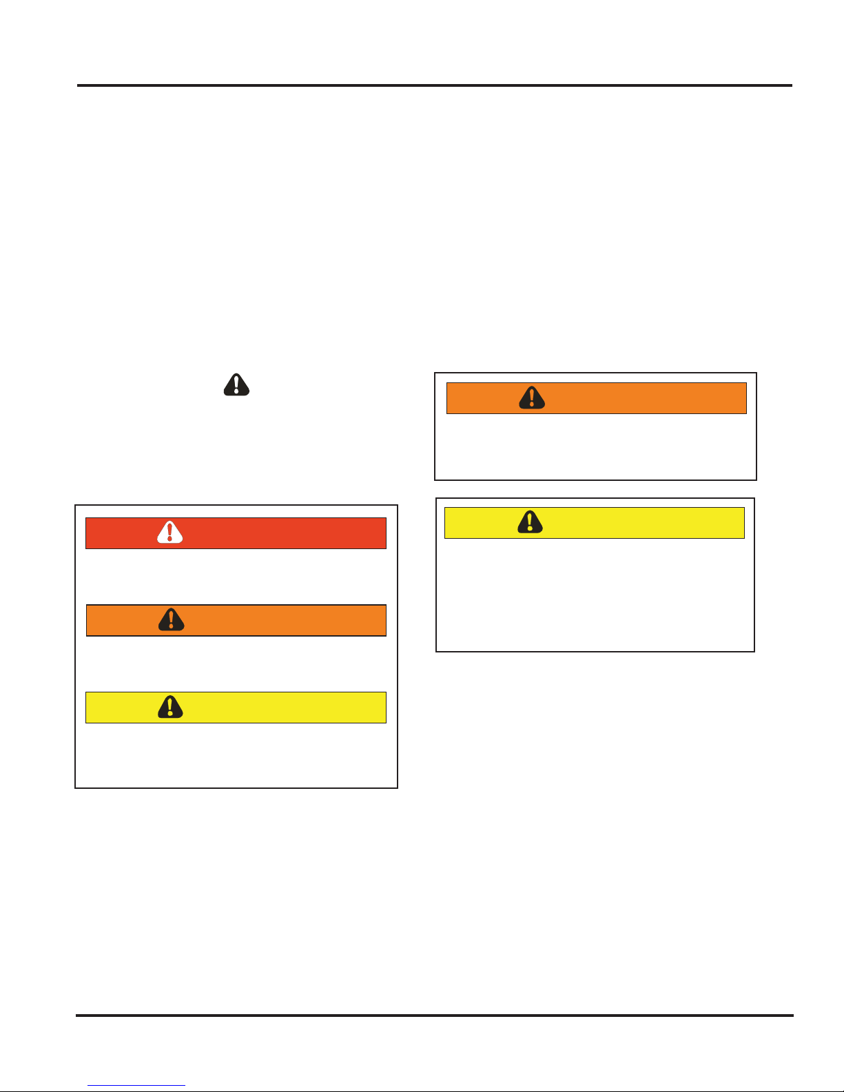
Safety Information
We have provided many important safety messages
throughout this manual and on the appliance.
ALWAYS read and obey all safety messages. This is
a safety alert symbol.
All safety messages will identify the hazard, tell
you how to reduce the chance of injury, and inform
you what can happen if the instructions are not
followed.
This symbol alerts personnel to hazards that can
kill or hurt you and others. All safety messages will
be preceded by a safety alert symbol and the word
“DANGER”, “WARNING” or “CAUTION”. These
words mean:
DANGER
Immediate hazards which WILL result in severe
personal injury or death.
WARNING
Hazards or unsafe practices which COULD
result in severe personal injury or death.
CAUTION
Hazards or unsafe practices which COULD
result in minor personal injury, product or
property damage.
WARNING
To avoid risk of serious injury or death,
repairs should not be attempted by
unauthorized personnel.
CAUTION
VIKING will not be responsible for any injury
or property damage from improper service
procedures. If performing service on your
own product, you must assume responsibility
for any personal injury or property damage
which may result.
To locate an authorized service agent, call:
Viking Customer Service
Phone No. 1-888-845-4641
Address your written correspondence to:
Viking Preferred Service
1803 HWY 82 West
Greenwood, MS 38930
© 2010 Viking Preferred Service
3

Warranty Information
Side-By-Side
Side-By-Side refrigerators and all of their components and accessories, except as detailed below*, are warranted to
be free from defects in material or workmanship under normal household use for a period of two (2) years from the
date of original retail purchase. Viking Range Corporation, warrantor, agrees to repair or replace, at its option, any
part which fails or is found to be defective during the warranty period.
*Glass (including light bulbs), painted and decorative items are warranted to be free from defective materials
or workmanship for a period of ninety (90) days from the date of original retail purchase. ANY DEFECTS MUST BE
REPORTED TO THE SELLING DEALER WITHIN NINETY (90) DAYS FROM DATE OF ORIGINAL RETAIL PURCHASE.
Viking Range Corporation uses the most up-to-date processes and best materials available to produce all color
finishes. However, slight color variation may be noticed because of the inherent differences in painted parts and
porcelain parts as well as differences in kitchen lighting, product locations, and other factors.
Six Year Full Warranty
Two Year Full Warranty
Any sealed refrigeration system component, as listed below, or any automatic ice maker is warranted to be free
from defective materials or workmanship in normal household use during the third through the sixth year from
the date of original retail purchase. Viking Range Corporation, warrantor, agrees to repair or replace, at its option,
any part which fails or is found to be defective during the warranty period.
Sealed Refrigeration System Components:
Condenser, Connecting Tubing, Dryer/Strainer
Compressor, Evaporator,
Twelve Year Limited Warranty
Any sealed refrigeration system component, as listed above, which fails due to defective materials or workmanship
in normal household use during the seventh through the twelfth year from the date of original retail purchase will be
repaired or replaced, free of charge for the part itself, with the owner paying all other costs, including labor.
Ninety (90) Day Residential Plus Warranty
This warranty applies to applications where use of the product extends beyond normal residential use. Examples
are, but not limited to, bed and breakfasts, fire stations, private clubs, churches, etc. This warranty excludes all
commercial locations such as restaurants, food service locations and institutional food service locations.
This warranty extends to the original purchaser of the product warranted hereunder and to each transferee owner
of the product during the term of the warranty.
This warranty shall apply to products purchased and located in the United States and Canada. Products must be
purchased in the country where service is requested. Warranty labor shall be performed by an authorized Viking
Range Corporation service agency or representative. Warranty shall not apply to damage resulting from abuse,
accident, natural disaster, loss of electrical power to the product for any reason, alteration, improper installation,
improper operation or repair or service to the product by anyone other than an authorized Viking Range
Corporation service agency or representative. Warranty shall not apply to damage resulting from indoor units
being used in outdoor situations. This warranty does not apply to commercial usage. This warranty does not
cover any food or medicine loss due to product failure. Warrantor is not responsible for consequential or
incidental damage whether arising out of breach of warranty, breach of contract, or otherwise. Some jurisdictions
do not allow the exclusion or limitation of incidental or consequential damages, so the above limitation or
exclusion may not apply to you.
Owner shall be responsible for proper installation, providing normal care and maintenance, providing proof of
purchase upon request, and making the appliance reasonably accessible for service. If the product or one of its
component parts contains a defect or malfunction during the warranty period, after a reasonable number of
attempts by the warrantor to remedy the defects or malfunctions, the owner is entitled to either a refund or
replacement of the product or its component part or parts. Replacement of a component part includes its free
installation. Warrantor’s liability on any claim of any kind, with respect to the goods or services covered hereunder,
shall in no case exceed the price of the goods or service or part there of which gives rise to the claim.
111 Front Street, Greenwood, Mississippi (MS) 38930 USA
For more product information, call 1-888-VIKING1 (845-4641), or visit our
© 2010 Viking Preferred Service
VIKING RANGE CORPORATION
662-455-1200
web site at http://www.vikingrange.com
4
Warranty Information
WARRANTY SERVICE
Under the terms of this warranty, service must be performed by a factory authorized Viking Range Corporation
service agent or representative. Service will be provided during normal business hours, and labor performed
at overtime or premium rates shall not be covered by this warranty. To obtain warranty service, contact the dealer
from whom the product was purchased, an authorized Viking Range Corporation service agent, or Viking Range
Corporation. Provide model and serial number and date of original purchase. For the name of your nearest
authorized Viking Range Corporation service agency, call the dealer from whom the product was purchased or
Viking Range Corporation. IMPORTANT: Retain proof of original purchase to establish warranty period.
The return of the Owner Registration Card is not a condition of warranty coverage. You should, however, return the
Owner Registration Card so that Viking Range Corporation can contact you should any question of safety arise which
could affect you.
Any implied warranties of merchantability and fitness applicable to the described halogen elements are limited
in duration to the period of coverage of the applicable express written limited warranties set forth above. Some
jurisdictions do not allow limitations on how long an implied warranty lasts, so the above limitation may not apply to
you. This warranty gives you specific legal rights, and you may also have other rights which may vary from jurisdiction
to jurisdiction.
£££ÊÀÌÊ-ÌÀiiÌÊUÊÀiiÜ`]ÊÃÃÃë«ÊÎnÎäÊ1-
Specification subject to change without notice.
VIKING RANGE CORPORATION
(662) 455-1200
www.vikingrange.com
© 2010 Viking Preferred Service
5

General Information
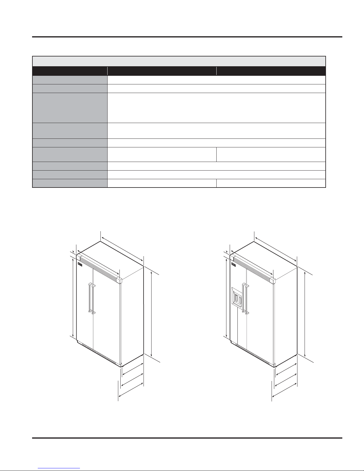
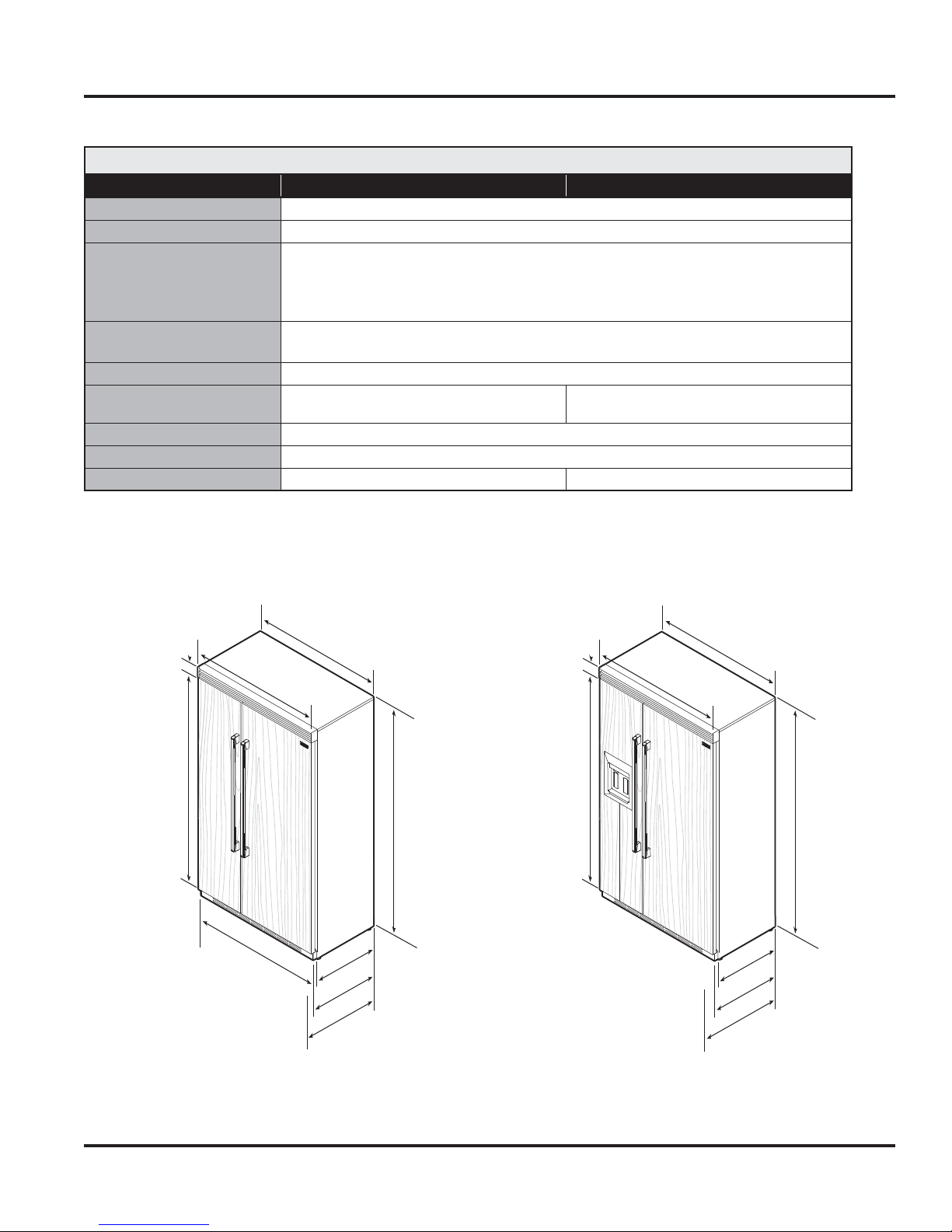
Specifications*
42” Professional Side-By-Side
Description VCSB542 VCSB542D
Overall width
Overall height from bottom
Overall depth from rear
To front edge of side trim:
To front of top grille:
To front of handle end-cap
Electrical requirements
115 volt, 60 Hz, 15 amp dedicated circuit; 3-wire cord with
Maximum amp usage
Inlet water requirements
1/4” copper tubing inlet waterline;
minimum 20 psi; maximum 120 psi
Refrigerant Type
Refrigerant Charge
Approximate shipping weight
652 lbs. (293.4 kg) 676 lbs. (304.2 kg
*Go to vikingrange.com for latest specifications.
82-3/4” (210.2 cm) min. to 84-1/16” (213.5 cm) max.
grounded 3-prong plug attached to product
42” (106.7 cm)
22-3/16” (56.4 cm)
24-11/16” (62.7 cm)
27-1/4” (69.2 cm)
9.9 amps
1/4” copper tubing inlet waterline;
minimum 35 psi; maximum 120 psi
HFC-134a
See rating label
3-19/32”
(9.1 cm)
VCSB542 VCSB542D
41”
42”
(106.7 cm)
(104.1 cm)
22-3/16”
(56.4 cm)
24-11/16”
(62.7 cm)
27-1/4”
(69.2 cm)
82-3/4”
(210.2 cm)
min.
to
84-1/16”
(213.5 cm)
max.
3-19/32”
(9.1 cm)
75-15/16”
(192.9 cm)
42”
(106.7 cm)
41”
(104.1 cm)
22-3/16”
(56.4 cm)
24-11/16”
(62.7 cm)
27-1/4”
(69.2 cm)
82-3/4”
(210.2 cm)
min.
to
84-1/16”
(213.5 cm)
max.
© 2010 Viking Preferred Service
6

General Information
Specifications*
42” Professional Side-By-Side
Description VISB542 VISB542D
Overall width
Overall height from bottom
Overall depth from rear
To front edge of side trim:
To front of top grille:
To front of handle end-cap
Electrical requirements
115 volt, 60 Hz, 15 amp dedicated circuit; 3-wire cord with
Maximum amp usage
Inlet water requirements
1/4” copper tubing inlet waterline;
minimum 20 psi; maximum 120 psi
Refrigerant Type
Refrigerant Charge
Approximate shipping weight
625 lbs. (293.4 kg) 676 lbs. (304.2 kg)
*Go to vikingrange.com for latest specifications.
82-3/4” (210.2 cm) min. to 84-1/16” (213.5 cm) max.
grounded 3-prong plug attached to product
42” (106.7 cm)
23-3/8” (59.4 cm)
24” (61.0 cm)
26-1/2” (67.3 cm)
9.9 amps
1/4” copper tubing inlet waterline;
minimum 35 psi; maximum 120 psi
HFC-134a
See rating label
3-19/32”
(9.1 cm)
75-15/16”
(192.9 cm)
VISB542 VISB542D
41”
42”
(106.7 cm)
(104.1 cm)
23-3/8”
(59.4 cm)
24”
(61.0 cm)
26-1/2”
(67.3 cm)
82-3/4”
(210.2 cm)
min.
to
84-1/16”
(213.5 cm)
max.
3-19/32”
(9.1 cm)
75-15/16”
(192.9 cm)
42”
(106.7 cm)
41”
(104.1 cm)
23-3/8”
(59.4 cm)
24”
(61.0 cm)
26-1/2”
(67.3 cm)
82-3/4”
(210.2 cm)
min.
to
84-1/16”
(213.5 cm)
max.
© 2010 Viking Preferred Service
7

General Information
Specifications*
48” Professional Side-By-Side
Description VCSB548 VCSB548D
Overall width
Overall height from bottom
Overall depth from rear
To front edge of side trim:
To front of top grille:
To front of handle end-cap
Electrical requirements
115 volt, 60 Hz, 15 amp dedicated circuit; 3-wire cord with
Maximum amp usage
Inlet water requirements
1/4” copper tubing inlet waterline;
minimum 20 psi; maximum 120 psi
Refrigerant Type
Refrigerant Charge
Approximate shipping weight
715 lbs. (321.8 kg) ) 735 lbs. (330.8 kg)
*Go to vikingrange.com for latest specifications.
82-3/4” (210.2 cm) min. to 84-1/16” (213.5 cm) max.
grounded 3-prong plug attached to product
48” (121.9 cm)
22-3/16” (56.4 cm)
24-11/16” (62.7 cm)
27-1/4” (69.2 cm)
9.9 amps
1/4” copper tubing inlet waterline;
minimum 35 psi; maximum 120 psi
HFC-134a
See rating label
3-19/32”
(9.1 cm)
75-15/16”
(192.9 cm)
VCSB548 VCSB548D
47”
48”
(121.9 cm)
(119.4 cm)
22-3/16”
(56.4 cm)
24-11/16”
(62.7 cm)
27-1/4”
(69.2 cm)
82-3/4”
(210.2 cm)
min.
to
84-1/16”
(213.5 cm)
max.
3-19/32”
(9.1 cm)
75-15/16”
(192.9 cm)
48”
(121.9 cm)
47”
(119.4 cm)
22-3/16”
(56.4 cm)
24-11/16”
(62.7 cm)
27-1/4”
(69.2 cm)
82-3/4”
(210.2 cm)
min.
to
84-1/16”
(213.5 cm)
max.
© 2010 Viking Preferred Service
8
General Information
Specifications*
48” Professional Side-By-Side
Description VISB548 VISB548D
Overall width
Overall height from bottom
Overall depth from rear
To front edge of side trim:
To front of top grille:
To front of handle end-cap
Electrical requirements
115 volt, 60 Hz, 15 amp dedicated circuit; 3-wire cord with
Maximum amp usage
Inlet water requirements
1/4” copper tubing inlet waterline;
minimum 20 psi; maximum 120 psi
Refrigerant Type
Refrigerant Charge
Approximate shipping weight
715 lbs. (321.8 kg) ) 735 lbs. (330.8 kg)
*Go to vikingrange.com for latest specifications.
82-3/4” (210.2 cm) min. to 84-1/16” (213.5 cm) max.
grounded 3-prong plug attached to product
48” (121.9 cm)
23-3/8” (59.4 cm)
24” (61.0 cm)
26-1/2” (67.3 cm)
9.9 amps
1/4” copper tubing inlet waterline;
minimum 35 psi; maximum 120 psi
HFC-134a
See rating label
3-19/32”
(9.1 cm)
75-15/16”
(192.9 cm)
VISB548 VISB548D
47”
48”
(121.9 cm)
(119.4 cm)
23-3/8”
(59.4 cm)
(61.0 cm)
26-1/2”
(67.3 cm)
24”
82-3/4”
(210.2 cm)
min.
to
84-1/16”
(213.5 cm)
max.
3-19/32”
(9.1 cm)
75-15/16”
(192.9 cm)
48”
(121.9 cm)
47”
(119.4 cm)
23-3/8”
(59.4 cm)
(61.0 cm)
26-1/2”
(67.3 cm)
24”
82-3/4”
(210.2 cm)
min.
to
84-1/16”
(213.5 cm)
max.
© 2010 Viking Preferred Service
9

General Information
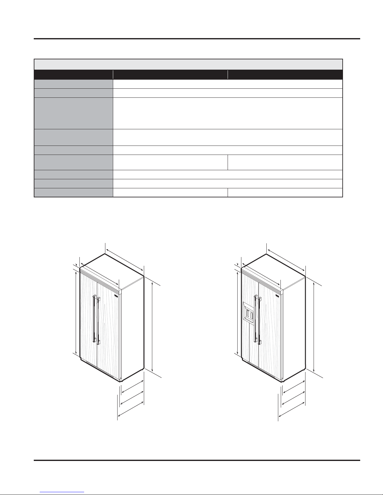
Specifications*
42” Designer Side-By-Side
Description DDSB542 DDSB542D
Overall width
Overall height from bottom
Overall depth from rear
To front edge of side trim:
To front of top grille:
To front of handle end-cap
Electrical requirements
115 volt, 60 Hz, 15 amp dedicated circuit; 3-wire cord with
Maximum amp usage
Inlet water requirements
1/4” copper tubing inlet waterline;
minimum 20 psi; maximum 120 psi
Refrigerant Type
Refrigerant Charge
Approximate shipping weight
642 lbs. (289 kg) 665 lbs. (299.3 kg)
*Go to vikingrange.com for latest specifications.
82-3/4” (210.2 cm) min. to 84-1/16” (213.5 cm) max.
grounded 3-prong plug attached to product
42” (106.7 cm
23-3/8” (59.4 cm)
24” (61.0 cm)
26” (66.0 cm)
9.9 amps
1/4” copper tubing inlet waterline;
minimum 35 psi; maximum 120 psi
HFC-134a
See rating label
3-1/2”
(8.9 cm)
75-15/16”
(192.9 cm)
DDSB542 DDSB542D
41”
42”
(106.7 cm)
(104.1 cm)
23-3/8”
(59.4 cm)
24”
(61.0 cm)
26”
(66.0 cm)
82-3/4”
(210.2 cm)
min.
to
84-1/16”
(213.5 cm)
max.
3-1/2”
(8.9 cm)
75-15/16”
(192.9 cm)
42”
(106.7 cm)
(104.1 cm)
41”
23-3/8”
(59.4 cm)
24”
(61.0 cm)
26”
(66.0 cm)
82-3/4”
(210.2 cm)
min.
to
84-1/16”
(213.5 cm)
max.
© 2010 Viking Preferred Service
10
General Information
Specifications*
42” Designer Side-By-Side
Description DFSB542 DFSB542D
Overall width
Overall height from bottom
Overall depth from rear
To front edge of side trim:
To front of top grille:
To front of handle end-cap
Electrical requirements
115 volt, 60 Hz, 15 amp dedicated circuit; 3-wire cord with
Maximum amp usage
Inlet water requirements
1/4” copper tubing inlet waterline;
minimum 20 psi; maximum 120 psi
Refrigerant Type
Refrigerant Charge
Approximate shipping weight
642 lbs. (289 kg) 665 lbs. (299.3 kg)
*Go to vikingrange.com for latest specifications.
82-3/4” (210.2 cm) min. to 84-1/16” (213.5 cm) max.
grounded 3-prong plug attached to product
42” (106.7 cm
23-3/8” (59.4 cm)
24” (61.0 cm)
26” (66.0 cm)
9.9 amps
1/4” copper tubing inlet waterline;
minimum 35 psi; maximum 120 psi
HFC-134a
See rating label
3-1/2”
(8.9 cm)
75-15/16”
(192.9 cm)
DFSB542 DFSB542D
41”
42”
(106.7 cm)
(104.1 cm)
23-13/16”
(60.5 cm)
24-3/4”
(62.9 cm)
Varies
82-3/4”
(210.2 cm)
min.
to
84-1/16”
(213.5 cm)
max.
3-1/2”
(8.9 cm)
75-15/16”
(192.9 cm)
42”
(106.7 cm)
41”
(104.1 cm)
23-13/16”
(60.5 cm)
24-3/4”
(62.9 cm)
Varies
82-3/4”
(210.2 cm)
min.
to
84-1/16”
(213.5 cm)
max.
© 2010 Viking Preferred Service
11

General Information
Specifications*
48” Designer Side-By-Side
Description DDSB548 DDSB548D
Overall width
Overall height from bottom
Overall depth from rear
To front edge of side trim:
To front of top grille:
To front of handle end-cap
Electrical requirements
115 volt, 60 Hz, 15 amp dedicated circuit; 3-wire cord with
Maximum amp usage
Inlet water requirements
1/4” copper tubing inlet waterline;
minimum 20 psi; maximum 120 psi
Refrigerant Type
Refrigerant Charge
Approximate shipping weight
642 lbs. (289 kg) ) 665 lbs. (299.3 kg)
*Go to vikingrange.com for latest specifications.
82-3/4” (210.2 cm) min. to 84-1/16” (213.5 cm) max.
grounded 3-prong plug attached to product
48” (121.9 cm)
23-3/8” (59.4 cm)
24” (61.0 cm)
26” (66 cm)
9.9 amps
1/4” copper tubing inlet waterline;
minimum 35 psi; maximum 120 psi
HFC-134a
See rating label
3-1/2”
(8.9 cm)
75-15/16”
(192.9 cm)
DDSB548 DDSB548D
47”
48”
(121.9 cm)
48”
(121.9 cm)
(119.4 cm)
23-3/8”
(59.4 cm)
(61.0 cm)
(66.0 cm)
24”
26”
82-3/4”
(210.2 cm)
Min.
to
84-1/16”
(213.5 cm)
max.
3-1/2”
(8.9 cm)
75-15/16”
(192.9 cm)
48”
(121.9 cm)
(119.4 cm)
47”
23-3/8”
(59.4 cm)
24”
(61.0 cm)
26”
(66.0 cm)
82-3/4”
(210.2 cm)
Min.
to
84-1/16”
(213.5 cm)
max.
© 2010 Viking Preferred Service
12
General Information
Specifications*
48” Designer Side-By-Side
Description DFSB548 DFSB548D
Overall width
Overall height from bottom
Overall depth from rear
To front edge of side trim:
To front of top grille:
To front of handle end-cap
Electrical requirements
115 volt, 60 Hz, 15 amp dedicated circuit; 3-wire cord with
Maximum amp usage
Inlet water requirements
1/4” copper tubing inlet waterline;
minimum 20 psi; maximum 120 psi
Refrigerant Type
Refrigerant Charge
Approximate shipping weight
642 lbs. (289 kg) ) 675 lbs. (303.8 kg)
*Go to vikingrange.com for latest specifications.
82-3/4” (210.2 cm) min. to 84-1/16” (213.5 cm) max.
grounded 3-prong plug attached to product
48” (121.9 cm)
23-3/8” (59.4 cm)
24” (61.0 cm)
varies
9.9 amps
1/4” copper tubing inlet waterline;
minimum 35 psi; maximum 120 psi
HFC-134a
See rating label
3-1/2”
(8.9 cm)
75-15/16”
(192.9 cm)
DFSB548 DFSB548D
47”
48”
(121.9 cm)
48”
(121.9 cm)
(119.4 cm)
23-13/16”
(60.5 cm)
24-3/4”
(62.9 cm)
Varies
82-3/4”
(210.2 cm)
Min.
to
84-1/16”
(213.5 cm)
max.
3-1/2”
(8.9 cm)
75-15/16”
(192.9 cm)
48”
(121.9 cm)
47”
(119.4 cm)
23-13/16”
(60.5 cm)
24-3/4”
(62.9 cm)
Varies
82-3/4”
(210.2 cm)
Min.
to
84-1/16”
(213.5 cm)
max.
© 2010 Viking Preferred Service
13
General Information
Warnings
Read and follow all instructions before using this
appliance to prevent the potential risk of fire,
electric shock, personal injury, or damage to the
appliance as a result of improper usage of the
appliance. Use appliance only for its intended
purpose as described in this manual.
To ensure proper and safe operation: appliance
must be properly installed and grounded by a
qualified technician. DO NOT attempt to adjust,
repair, service, or replace any part of your appliance
unless it is specifically recommended in this manual.
All other servicing should be referred to a qualified
servicer.
Make sure that incoming voltage is the same as
unit rating. An electric rating plate specifying
voltage, frequency, wattage, amperage, and phase
is attached to the product.
Electrical Requirements
Assure that the electrical installation is adequate
and in conformance with the National Electrical
Code, ANSI/NFPA 70-latest edition or Canadian
Electrical Code C22.1-1998 and C22.2 No. 0-M91
(or latest edition), and all local codes and
ordinances. A 115 volt, 60 Hz, 15 amp, fused,
electrical supply is required. It is required that
a separate circuit serving only this appliance be
provided. This appliance is equipped with a power
supply cord having a 3-prong grounding plug.
To minimize possible shock hazard, the cord must
be plugged into a mating 3-prong, grounding-type
wall receptacle. DO NOT use an extension cord.
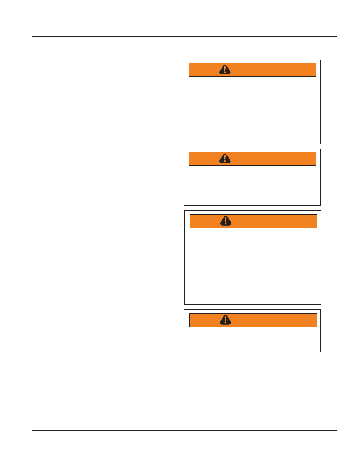
WARNING
TIP OVER HAZARD
Appliance is top heavy and tips easily when not
completely installed. Keep doors closed until
appliance is completely installed and secured
per installation instructions.
Use two or more people to move and install
appliance. Failure to do so can result in death
or serious injury.
WARNING
ELECTRICAL SHOCK HAZARD
Disconnect power or turn power disconnect
switch to “OFF” position before removing top
grille. Failure to do so can result in death or
electrical shock.
WARNING
ELECTRICAL SHOCK HAZARD
Plug into a grounded 3-prong outlet. If a
2-prong wall receptacle is encountered,
contact a qualified electrician.
DO NOT remove ground prong.
Unit must be grounded at all times.
DO NOT use an adapter.
DO NOT use an extension cord.
Failure to follow these instructions can result in
death, fire, or electrical shock.
Tip Over Hazard
Most of the unit’s weight is at the top. Extra care is
needed when moving the unit to prevent tipping.
Keep doors closed until appliance is completely
installed and secured per installation instructions.
Use two or more people to move and install
appliance. Failure to do so can result in death or
serious injury.
© 2010 Viking Preferred Service
WARNING
BURN HAZARD
DO NOT touch condenser coils near defrost
pan. Doing so can result in burns.
14
General Information
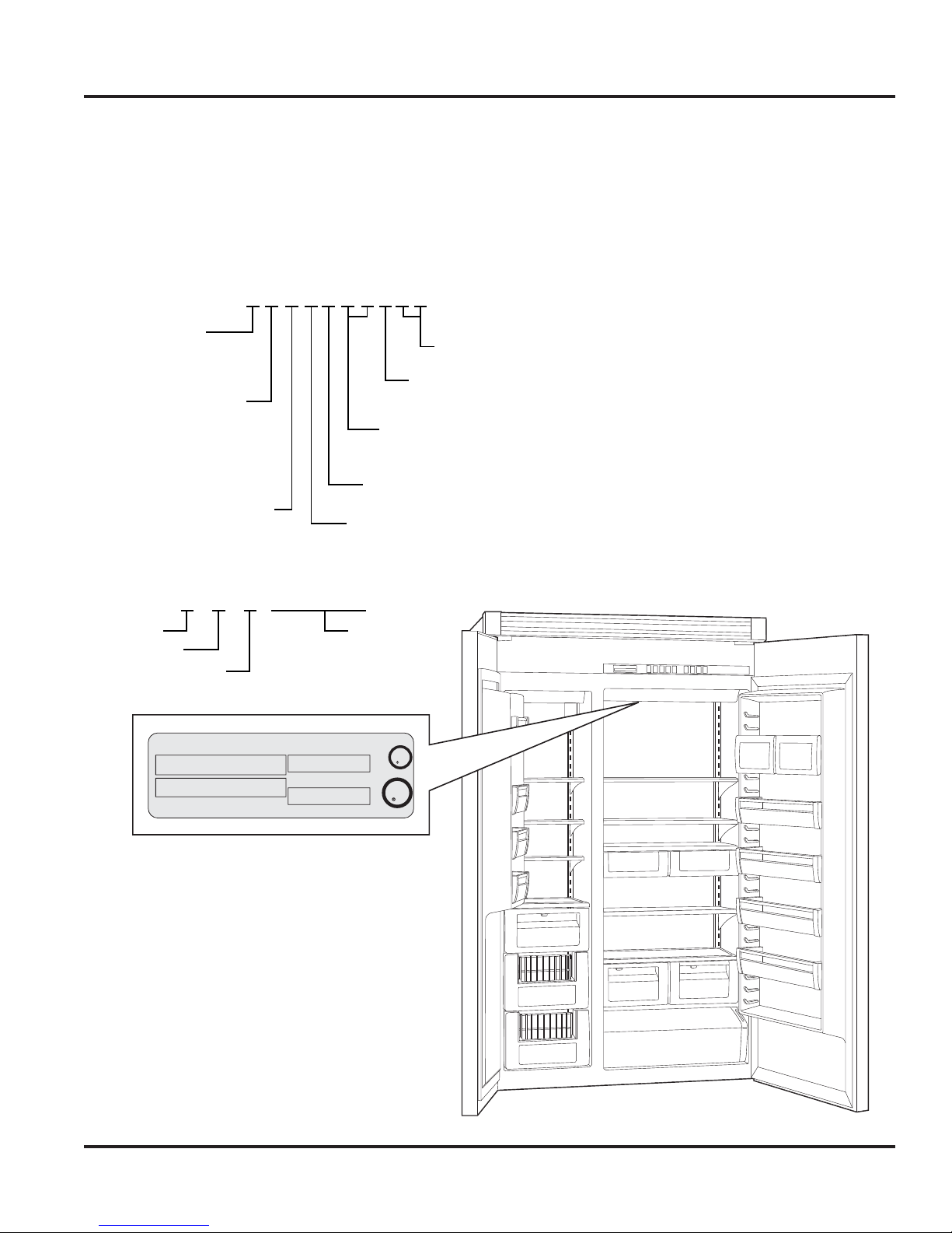
Model – Serial Number Matrix
The serial number and model number for your
appliance are located on the identification plate
mounted on the upper left side of the door
opening.
Model Numbers
VCSB542RSS
V = Professional
D = Designer
C = Commercial Door
D = Desinger Door
F = Full Overlay Door
I = Integrated Door
S = Side-By-Side
Serial Numbers
02 05 09 R00001169
Month
Day
Year of Manufacture
VIKING RANGE CORP.
GREENWOOD, MISSISSIPPI 38930
MODEL/MODELE
NUMBER/NUMERO
SERIAL/SERIE
NUMBER/NEMERO
PE920095
VCSB542RSS
020509R00001175
B = Built-In
Serial Number
LISTED HOUSEHOLD
REFRIGERATOR 35NN
5.75 oz R134a
115 VAC/60 HZ
AMPS: 5.7
R = Right Hand
L = Left Hand
42” Wide
48” Wide
5 = Series
U
L
U
L
C
SS=Stainless
© 2010 Viking Preferred Service
15
Operation
Settings and Functions
In order for your new refrigerator to work properly,
it is important that you understand its various
features, controls, and how to use them.
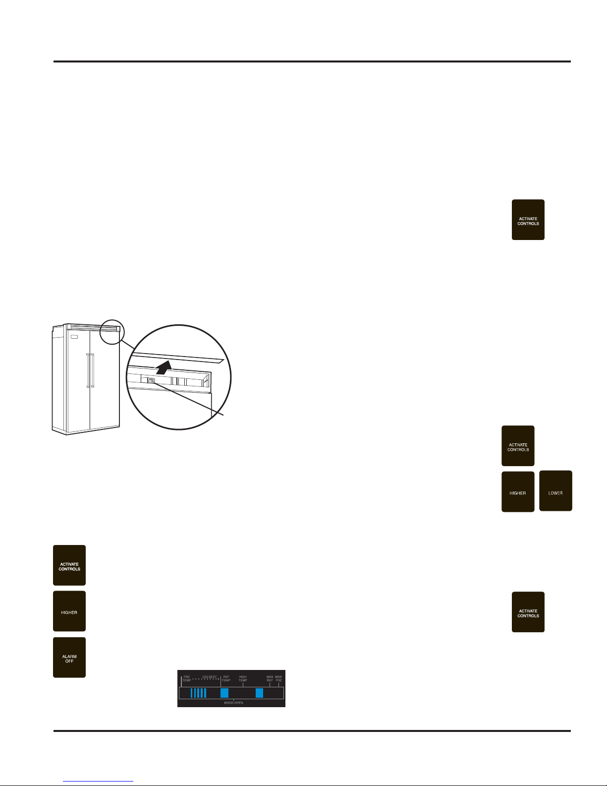
Power On/Off Switch (Power Interruption Switch)
The power on/off switch is located behind your
refrigerator’s top grille. It is used to turn the power
“OFF” when cleaning the refrigerator or changing
the light bulbs. Your refrigerator arrives from the
factory with the power interruption switch “ON”.
To turn power “OFF”, remove the center grille
blade. Press the power on/off switch to the “OFF”
position.
To turn power “ON”, press power on/off switch to
the “ON” position. Replace the center grille blade.
Power Switch
IMPORTANT: Be sure the power on/off switch is in the
“ON” position after cleaning or changing light bulbs.
Showroom Mode Initiation
Showroom mode allows electronic controls and
interior lights to function independently of the
refrigeration system.
To exit Showroom mode: Press and hold the
“ACTIVATE CONTROLS” pad. While holding, press
and hold the “HIGHER” and “ALARM OFF” pad
simultaneously. One beep will be heard indicating
that sequence was entered properly. Continue
holding until three beeps are heard. The display will
revert to normal operation
Electronic Temperature Settings
Your refrigerator’s electronic controls
are located behind the door above the
cabinet interior. To activate the electronic
control panel, press “ACTIVATE CONTROLS” pad.
All other pads, except the “Alarm Off” pad, will
remain inactive until the ”ACTIVATE CONTROLS”
pad is pressed. Once activated, pad remains
programmable for at least ten minutes.
When you first plug your new refrigerator in, you
will find that five bars of nine are displayed. This
means that all unit controls are pre-set at the midrange setting. Wait 24 hours after plug-in for the
cabinets to reach this setting. After 24 hours, you
may adjust controls as desired. The warmest setting
displays one bar, while the coldest setting shows
nine bars.
To adjust the refrigerator or freezer
temperature, simply press the
”ACTIVATE CONTROLS” pad, then
“REF TEMP” pad or “FRZ TEMP” pad.
Press the “HIGHER” or “LOWER” pad to
adjust temperature setting one level at
a time. Holding down the “HIGHER” or
“LOWER” pad adjusts temperature more
than one level at a time.
To enter Showroom mode: Press and hold
the “ACTIVATE CONTROLS” pad. While
holding, press and hold the “HIGHER”
and “ALARM OFF” pad simultaneously.
One beep will be heard indicating that
sequence was entered properly. Continue
holding until three beeps are heard and
then the Blue LED two steps to the right of
the “HIGH TEMP” indicator will illuminate.
Showroom mode is entered.
© 2010 Viking Preferred Service
Key Press Confirmation
The key press confirmation is the “beep” heard when
a control pad is pressed. The confirmation can be
activate or inactive.
To activate the key press confirmation,
press and hold the “ACTIVATE CONTROLS”
pad for three to five seconds. Three beeps
will be heard confirming the key press confirmation
has been deactivated.
To activate the key press confirmation, press and
hold the “ACTIVATE CONTROLS” pad until
confirmation beep is heard.
16
Operation
Settings and Functions (continued)
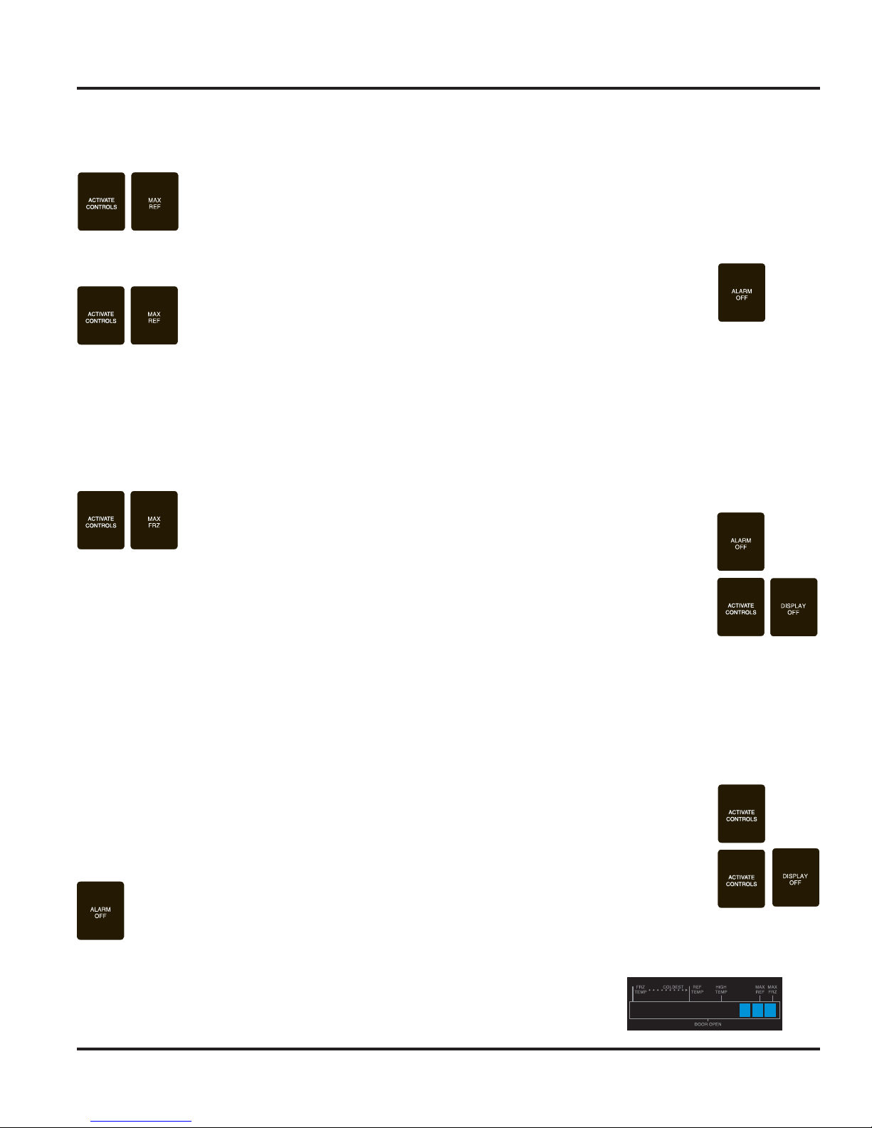
Max Refrigerator Mode
Max refrigerator mode adjusts
the refrigerator temperature to
the coldest setting for four
hours, at the end of which the
refrigerator’s temperature automatically returns to
its previous setting.
To activate the max refrigerator
mode, simply press the
”ACTIVATE CONTROLS” pad,
followed by the “MAX REF” pad.
The indicator light will glow to let you know you’ve
turned on the max refrigerator mode.
To deactivate the max refrigerator mode before
the end of the four hour cycle, press the
”ACTIVATE CONTROLS” pad, followed by the
“MAX REF” pad.
Max Freezer Mode
Max freezer mode adjusts the
freezer temperature to the
coldest setting for 4 hours, at the
end of which, the freezer temperature automatically
returns to its previous setting.
To activate the max freezer mode, press the
”ACTIVATE CONTROLS” pad, followed by the
“MAX FRZ” pad. The indicator light will glow to
let you know you have turned on the max freezer
mode.
High Temperature Alarm
The high temperature alarm sounds and an
indicator light glows if the refrigerator or the freezer
temperature is too high for two hours. A blinking
light signals which part of the appliance is affected.
The alarm will end when the temperature is brought
back to a proper setting.
To deactivate the high temperature
alarm, press the “ALARM OFF” pad.
Thermistor Alarm
The thermistor alarm is a special feature that
electronically senses temperature problems. The
thermistor alarm will sound and indicator lights 4-7 will
scroll if the thermistor is not operating properly. The
alarm can be deactivated by pressing the “ALARM
OFF” pad on your refrigerator’s control panel. If the
alarm continues to sound, contact an authorized
Viking Range Corporation technician immediately.
Display Panel
To activate Control panel and display,
press the ”ACTIVATE CONTROLS” pad.
To deactivate Control panel and display,
press the ”ACTIVATE CONTROLS” or
“DISPLAY OFF pad.
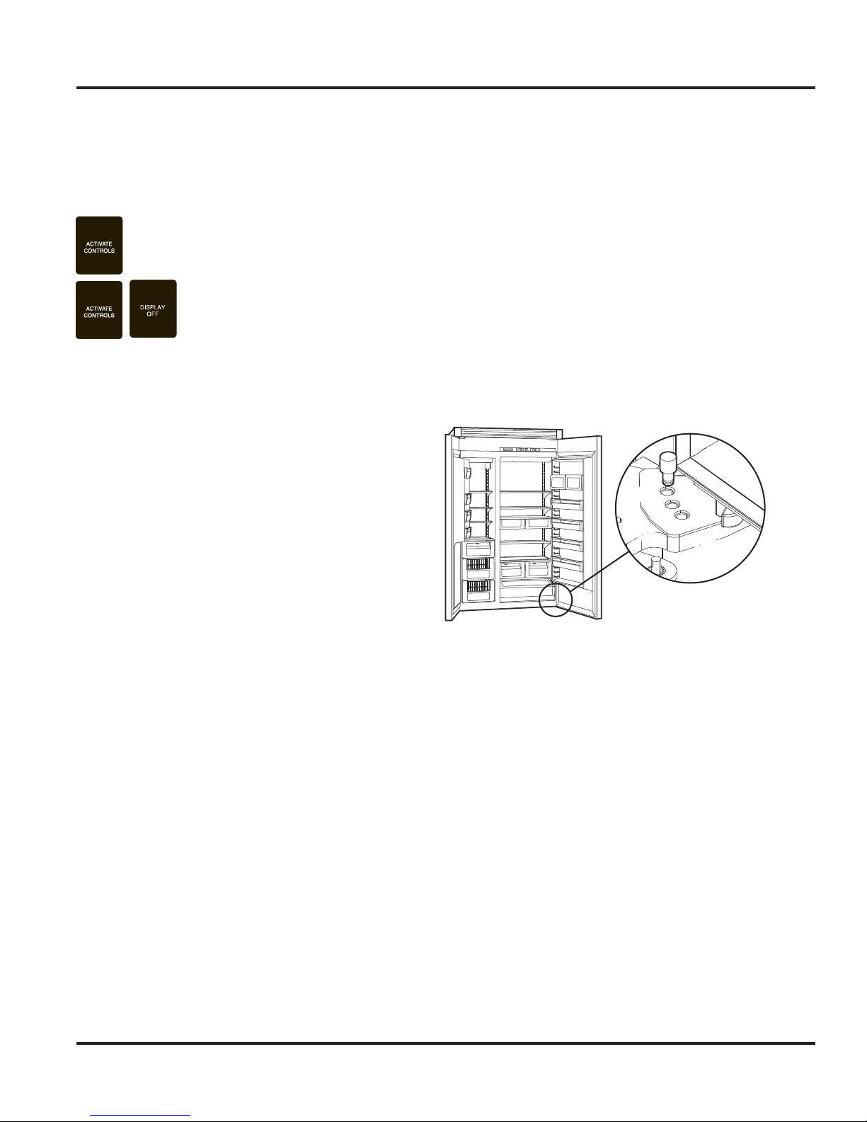
Sabbath Mode
Sabbath mode is used to disable interior lights and
alarms for observance of the Sabbath.
To deactivate the max freezer mode before
the end of the 4 hour cycle, simply press the
”ACTIVATE CONTROLS” pad, followed by the
“MAX FRZ” pad.
Door Open Alarm
The door open alarm sounds and an indicator light
blinks if either door is left open for more than three
minutes.
To deactivate the door open alarm, press
the “ALARM OFF” pad or close the door
that is open.
© 2010 Viking Preferred Service
Before the Sabbath mode is engaged, the bale arm
of the ice maker needs to be raised until it clicks into
the detent. This turns off the power to the ice maker.
To enter Sabbath mode, press the
”ACTIVATE CONTROLS” pad to activate
the control panel. Then, press and hold
“ACTIVATE CONTROLS” and “DISPLAY
OFF” pads simultaneously for three
seconds. It will beep three times and
light the three right blue squares so
you will know that you have activated
Sabbath mode.
When your refrigerator is in Sabbath mode, interior
lights, display (excluding
the three right hand side
lit blue squares), and
alarms are disabled.
17
Operation
120˚120˚
110˚
110˚
Settings and Functions (continued)
If your refrigerator loses power while in Sabbath
mode, it will return to the Sabbath mode when
power is reestablished.
To exit the Sabbath mode, press the
”ACTIVATE CONTROLS” pad. Then,
press and hold “ACTIVATE CONTROLS”
and “DISPLAY OFF” pads
simultaneously for three seconds.
You will then hear three beeps
letting you know that you have
turned the Sabbath mode “OFF”.
Once your refrigerator has left the Sabbath mode,
the bale arm of the ice maker needs to be pushed
downward until it is no longer in the detent. This
will restore power to the ice maker.
Setting the Controls
Adjust control setting by using a high quality
household temperature thermostat that can read
temperatures between -5° to -50°F (-21° to 10°C).
Checking the Temperature (freezer)
Place the thermometer snugly between frozen
packages in freezer section. Wait five to eight
hours, then check the temperature. If the freezer
temperature is not 0° to 2°F (-17° to -16°C), adjust
the temperature control one number at a time.
Then, check the temperature again in five to
8 hours.
Note: Allow 24 to 48 hours after installation before
looking for ice in your ice drawer. You should
discard the first three full drawers of ice produced
by your refrigerator, and should also throw out the
first drawer full of ice your refrigerator produces
after extended periods of non-use.
Door Stop Adjustment
Your refrigerator is factory set at 110° door stop
position. To change to either the 90° or 120°
position, remove the door stop pin located in the
bottom hinge using a 3/16” allen wrench. For 120°
swing, move the pin to stop hole closest to the unit.
For 90° swing, move pin to stop hole farthest from
the unit.
90˚90˚
Light Bulb
Checking the Temperature (refrigerator)
Place the thermometer in a glass of water in the
middle of the refrigerator. Wait five to eight hours,
and then check the temperature. If the refrigerator
temperature is not 38° to 40°F (3° to 4°C), adjust
the control one number at a time. Check again after
five to eight hours.
Automatic Ice Maker
After the refrigerator reaches normal temperature,
the ice maker fills with water and begins operating.
Under normal conditions, the ice maker will
produce seven to nine batches of ice per 24 hour
period.
© 2010 Viking Preferred Service
Disconnect power at breaker or turn power
disconnect switch to the off position. Lightly grasp
light cover with both hands and pull down. Replace
bulb with an incandescent, medium base tubular
bulb with a maximum of 40 watts. Replace cover by
engaging light bracket with the back fingers on the
light cover. Once engaged, snap the front fingers
on the light cover.
Note: The clear section of the light cover is
considered the back section. Reconnect power
or turn power disconnect switch to the “ON”
position.
18
Operation
1
3
1
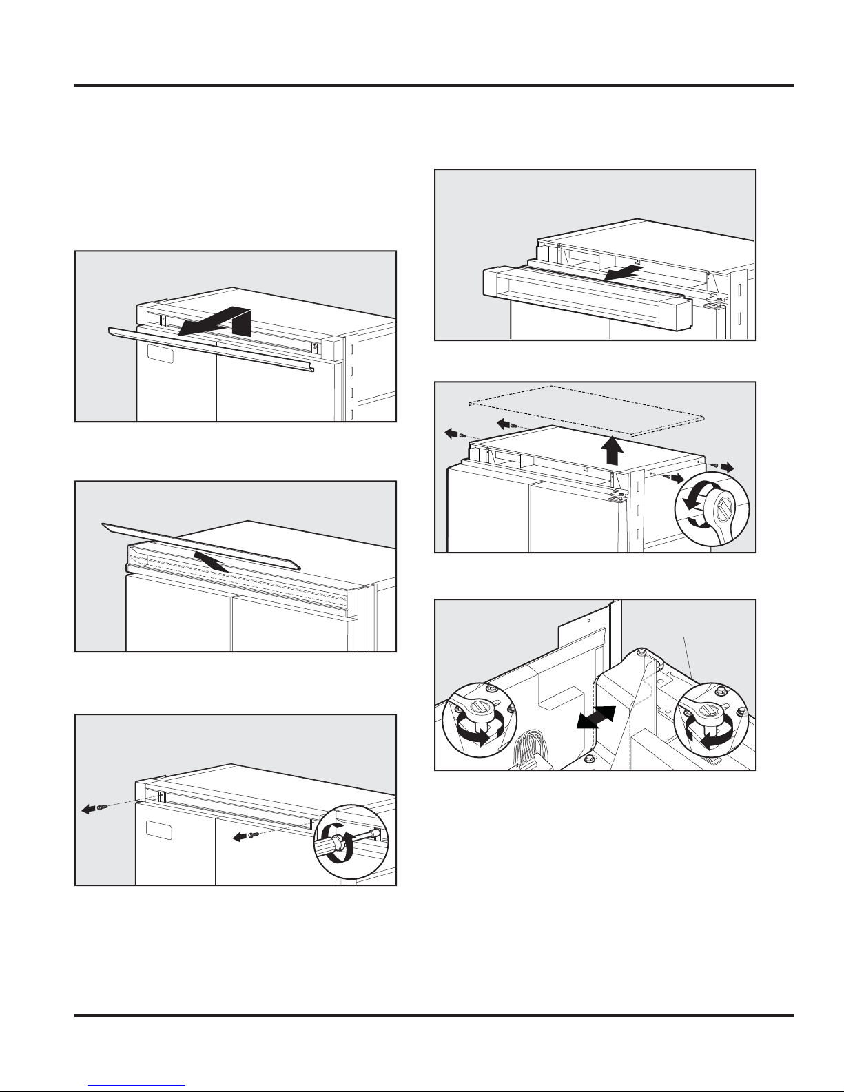
Door Hinge Adjustment
Removal of the upper grill assembly allows access
to door hinge for adjustment.
To remove upper grill:
1a. (Professional) Lift center grille louver up and
pull out.
1b. (Designer) Pull the center grille louver up at an
angle and pull out.
3. Remove grille assembly.
4. Remove four side screws and remove unit top.
2
2. Using an 8” magnetic nut driver, remove the
two 1/4” screws.
5. Loosen the four hinge screws. Adjust door.
Front of unit
2
6. Reverse procedure for reinstallation.
© 2010 Viking Preferred Service
19
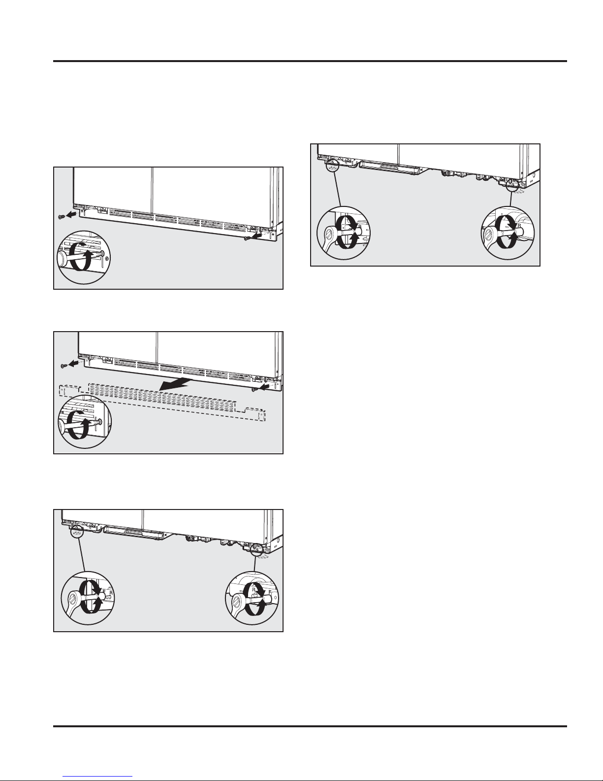
Operation
Height Adjustment
Removal of the kickplate allows access to rollers
and stabilizing legs for height adjustment.
1. Remove lower kickplate screws using a Phillips
screwdriver.
2. Remove upper kickplate screws using a Phillips
screwdriver. Remove kickplate assembly.
2
4. Using a 5/16” head wrench, turn the rear (R)
adjustment screws to raise or lower the rear of
the refrigerator.
Note: DO NOT use an electric device.
Overtightening can cause damage.
5. Reinstall kickplate.
3. Using a 5/16” head wrench, turn the front (F)
adjustment screws to raise or lower the front of
the refrigerator.
Note: DO NOT use an electric device.
Overtightening can cause damage.
© 2010 Viking Preferred Service
20
Diagnostics
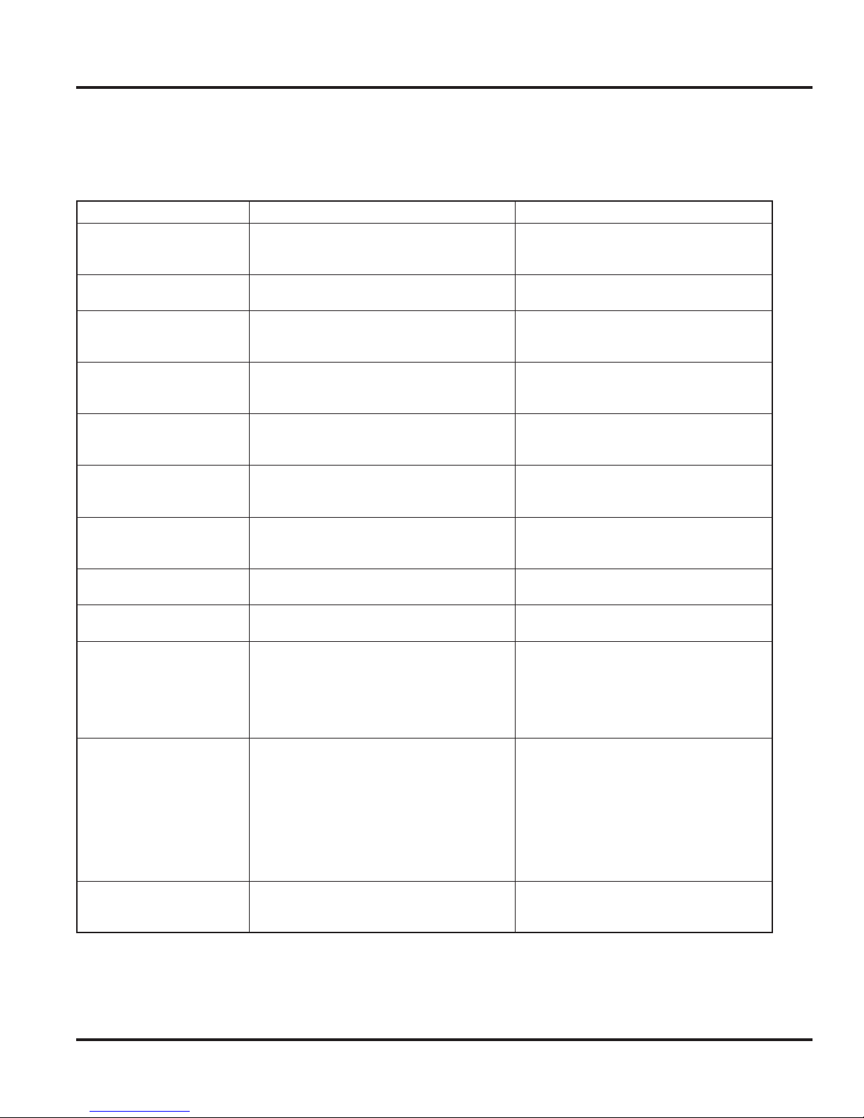
Display Panel Operation
The unit being serviced has a control panel that allows operation of the unit as well as diagnostic abilities.
See the information below for details.
Operation Description How to Access Function
Keyboard Entry Tone Indicates a pad was pressed, command was
read, and accepted
Command Accepted Tone Three short tones sound indicating a
command has been accepted
Activate Controls Pad If the pad is activated, the display panel
remains active at least 10 minutes after the
door is closed
Freezer Temperature Pad Freezer indicator light will glow and freezer
temperature will be displayed.
Factory setting is 5
Ref Temp Pad Refrigerator indicator light will glow and
refrigerator temperature will be displayed.
Factory setting is 5
Higher Temp Pad Raises temperature settings one bar at a
time
Lower Temp Pad Lowers temperature settings one bar at a
time
Max Freezer Pad Sets freezer temperature to coldest setting.
Factory setting is 4 hours
Max Ref Pad Sets refrigerator temperature to coldest
setting. Factory setting is 4 hours
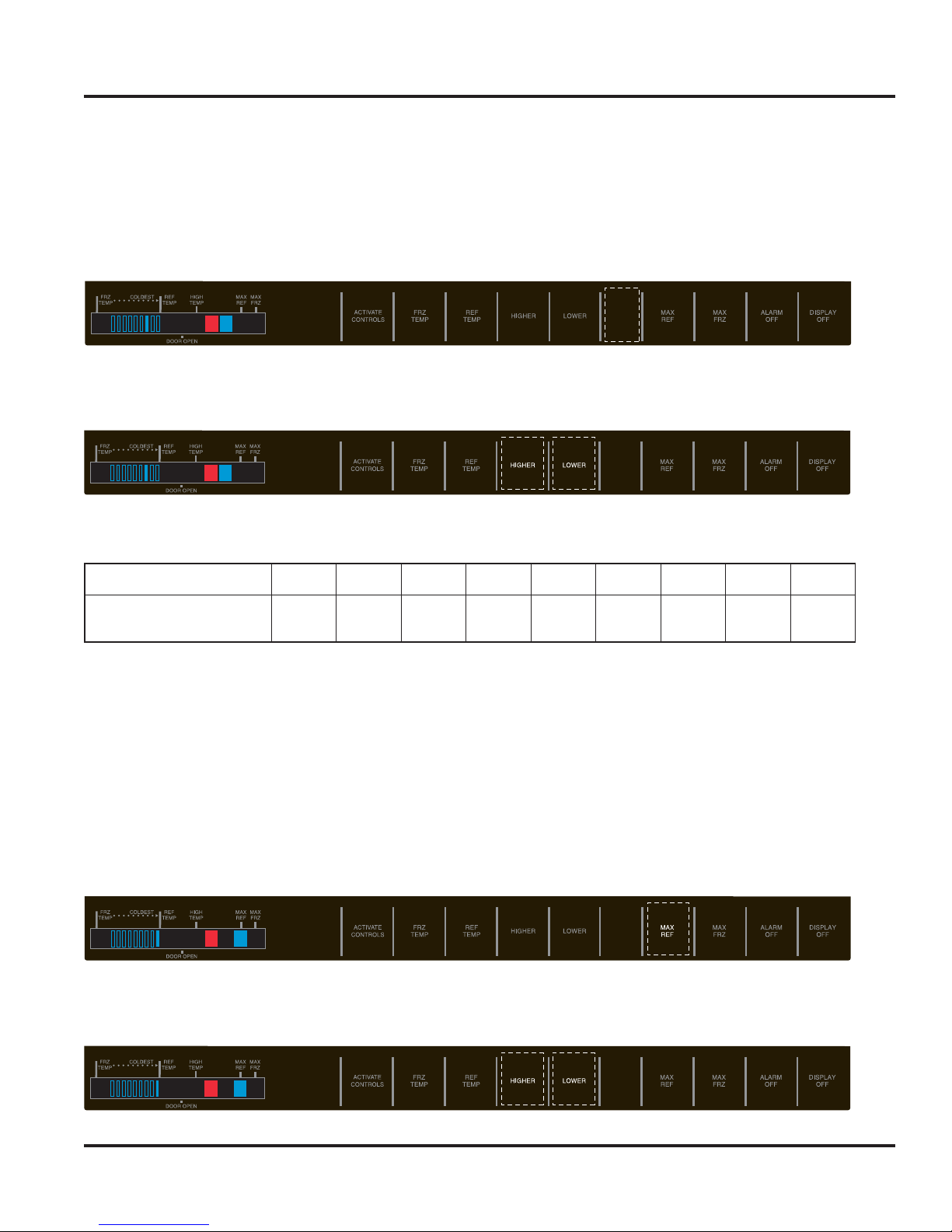
Alarm Off Pad Turns alarm signal off Press “ALARM OFF” to terminate audible
Hidden Button Puts unit in program mode Open refrigerator door. Press “ACTIVATE
Display Off Pad Deactivates control panel Press “DISPLAY OFF” pad to deactivate
To turn off entry tone, press and hold
“ACTIVATE CONTROLS” pad for
3 to 5 seconds
Press the “ACTIVATE CONTROLS” pad
Press “HIGHER TEMP” or “LOWER TEMP”
pad
Press “HIGHER TEMP” or “LOWER TEMP”
pad
Press “HIGHER TEMP” pad. To raise
temperature at a faster rate, hold the pad
down
Press “LOWER TEMP” pad. To lower
temperature at a faster rate hold, the
pad down
Press “MAX FRZ” Pad to engage.
A second press will disengage feature
Press “MAX REF” pad to engage.
A second press will disengage feature
alarm, visual indicator light will continue
to blink until alarm condition is cleared or
permanently disabled. To reactivate,
press and hold “ALARM OFF” pad for
3 seconds
CONTROLS” pad. Press hidden button
(refer to control panel for unit being
serviced). Within 6 seconds of pressing
the hidden button, press “MAX REF”,
“MAX FRZ”, “MAX REF”, “MAX FRZ”.
Tone will sound 3 times and control will
be in program mode A. Refer to Program
Mode section
display. Press “ACTIVATE CONTROLS”
pad to reactivate
© 2010 Viking Preferred Service
21
Diagnostics
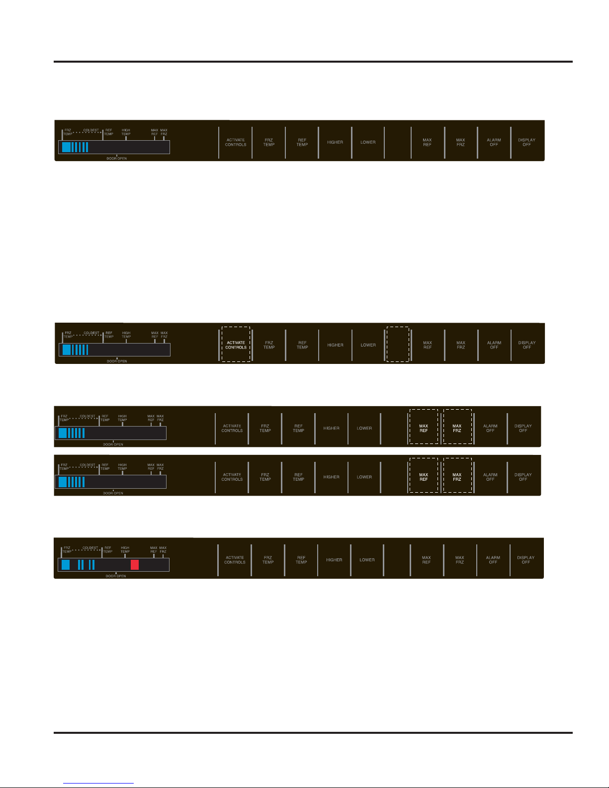
Program Modes
Side-By-Side Control Panel
Two programming modes are available for the side-by-side unit. Mode A allows the reading of both the
Freezer and Fresh Food Thermistor. It is also used to program the following:
Ê UÊivÀÃÌÊÕÀ>ÌÊÜiÊÃiÌÊÌÊÛiÌ>ÊivÀÃÌÊÊ`iÊ®Ê
Ê UÊ6Êëii`Êëii`ÊÊÜVÊV«ÀiÃÃÀÊÜÊ«iÀ>Ìi®
Ê UÊÊÀiiâiÀÊ>`ÊÀiÃÊ`ÊÕÌÉÕÌ"ÕÌÊvviÀiÌ>ÊÌi«iÀ>ÌÕÀiÊ`vviÀiViÊLiÌÜiiÊVÞViʺ"»Ê>`Ê
cycle “ON” temperatures). Mode B is used for all other programmable functions. To access the program
modes follow the steps below.
1. Open the refrigerator door.
2.
Press “ACTIVATE CONTROLS” pad (to right of display window). Then press “HIDDEN BUTTON” pad
(located between “Lower” and “Max Ref” pad).
1 2
3. Within 6 seconds press the “MAX REF” pad, then press the “MAX FRZ” pad, the “MAX REF” pad, then
press the “MAX FRZ”.
1 2
3 4
4. An audible tone will sound three times confirming the unit is in Program Mode A and the orange LED to
the right of the HIGH TEMP indicator will illuminate.
© 2010 Viking Preferred Service
22
Diagnostics
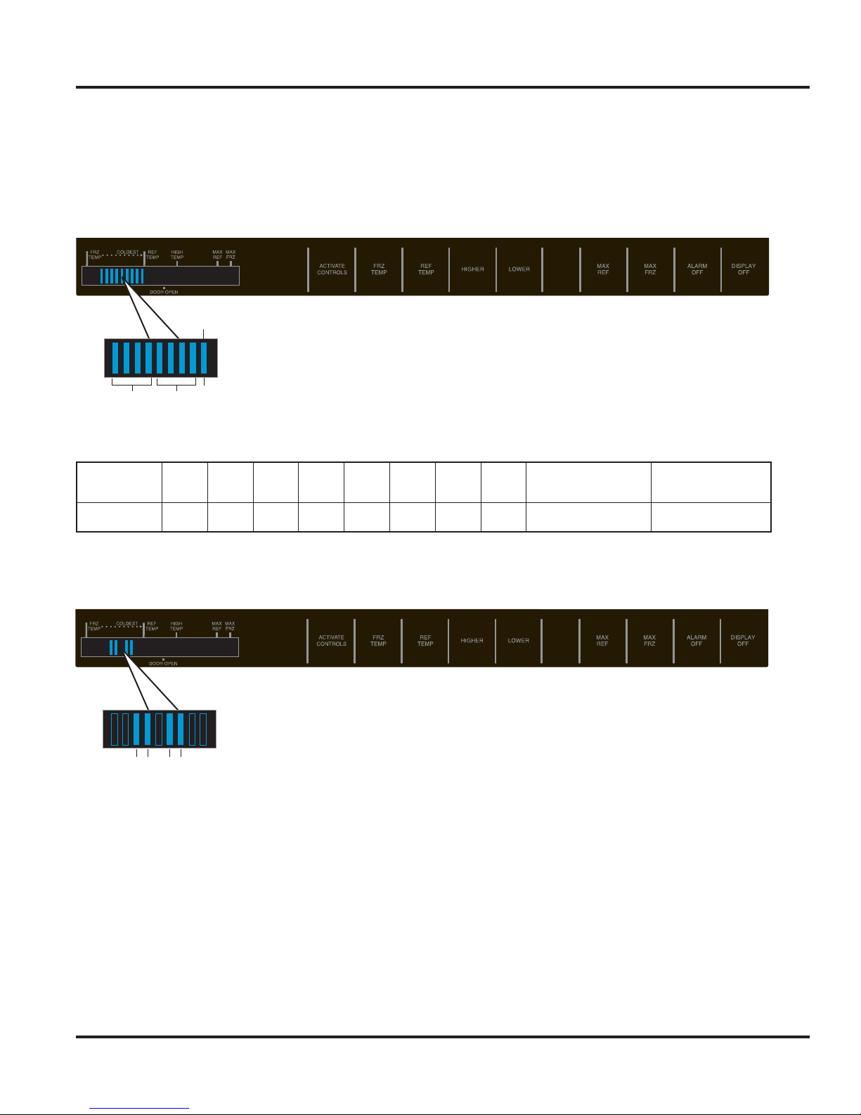
Mode A Functions
Reading Temperature Display
The temperature display will show thermistor temperature in binary code. The display has nine indicator
lights that will light up to display the temperature. Lights 1 – 4 indicate the first digit of the compartment
temperature and lights 5 – 8 indicate the second digit of the compartment temperature. The ninth light will
light up for a negative temperature.
Negative temp
To read the temperature of the unit from the display, refer to the code chart below.
Below is an example of the Fresh Food Thermistor. In the first group of 4 indicators (10’s column) indicator 3
and 4 are lit. In the second group of 4 indicators (0’s column) indicator 6 and 7 are lit. Add all the values to
calculate the compartment temperature.
1-4 5-8 9
Indicator
Value
12345678 9
Not Illuminated
84218421+ Temperature - Temperature
9
Illuminated
34 67
Indicator 3 is illuminated this is a value of 2 or 20 degrees
Indicator 4 is illuminated this is a value of 1 or 10 degrees
Add Indicator 3 and 4 together to get a total temp of 30 degrees for the 10’s column.
Indicator 6 is illuminated this is a value of 4 or 4 degrees
Indicator 7 is illuminated this is a value of 2 or 2 degrees
Add Indicator 6 and 7 together to get a total temp of 6 degrees for the 1’s column.
Indicator 9 is not illuminated so the temperature is positive.
The compartment temperature for this example would be 36 degrees.
© 2010 Viking Preferred Service
23
Diagnostics
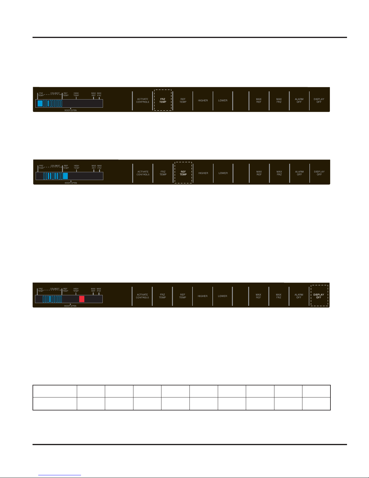
Mode A Functions (continued)
Freezer Thermistor Temperature
When Service Mode A is entered, press the “FRZ TEMP” pad. Using the code on page 23, add up the value
of the illuminated bars to get the current Freezer temp. The example below shows a Freezer Temp of 20˚F.
Refrigerator Thermistor Temperature
When Service Mode A is entered, press the “REF TEMP” pad. Using the code on page 23, add up the value
of the illuminated bars to get the current Fresh Food temp. The example below shows a Fresh Food temp of
36˚F.
Optional Conventional Defrost
The unit comes set from the factory for Adaptive Defrost. In the event that more or less defrost intervals are
required, the unit can be set for a conventional defrost cycle. In this mode the defrost program can be set to
predetermined defrost times. Note: The defrost intervals are set in SERVICE MODE A. In order to activate the
conventional defrost system, it must be initiated in SERVICE MODE B. See Defrost Mode Selection–Service
Mode B on Page 27.
To change the defrost time, place the unit in Program Mode A (see Program modes on page 22). When you have
entered SERVICE MODE A, Press and hold the “DISPLAY OFF” pad for 3 seconds. 1 audio confirmation beep will
be heard. Both the FRZ temp and REF temp LED will extinguish. The orange LED to the right of the High Temp
LED and (1) bar will be lit. The default conventional defrost setting is the 4th bar (8 hours) shown below.
The Conventional Defrost time will be displayed by use of one of the temperature indicators. The times can
be set to 4, 5, 6, 8, 12, 16, 18, 20, and 24 hours of Compressor Run Time (CRT).
The intervals are changed by using the HIGHER and LOWER Temp key pads. Each press of the “HIGHER”
pad will decrease the defrost time by one level while each press of the “LOWER” pad once will increase the
defrost time by one level in the other direction. Once Conventional defrost is initiated in SERVICE MODE B,
the first defrost will always be 4 hours of CRT regardless of the level it has been changed to.
The indicator light and corresponding Defrost Times are listed below.
Indicator
Defrost Time
*Default setting
To exit Adjustable Conventional Defrost, press the “ACTIVATE CONTROLS” key.
© 2010 Viking Preferred Service
123
4 hours 5 hours 6 hours
4*
8 hours
56789
12 hours 16 hours 18 hours 20 hours 24 hours
24
Diagnostics
Mode A Functions (continued)
VCC Compressor Frequency
This allows adjustment of the compressor frequency used when the compressor is running at low speed.
(A new LV board comes at default setting of 7.) Place the unit in Program Mode A (see Program Mode on
page 22). Press the “HIDDEN BUTTON” pad. An audio confirmation beep will be heard. The blue LED to the
right of the orange LED will be lit. The Compressor Frequency will be displayed by having one of the nine
segment indicators being lit.
The compressor speed frequency value is changed by using the Higher Temp and Lower Temp keys. Pressing
the “HIGHER TEMP” key once will lower the frequency by one level; pressing the “LOWER TEMP” key once
will increase the frequency.
The indicator light and corresponding Compressor Frequencies are listed below.
Indicator
VCC
Compressor Frequency
*Default setting
Temperature Differentials for Freezer and Fresh Food Compartments
Note: These settings should not be changed unless instructed by Technical support or if the settings are not
at the defaults. Improper operation of the unit can result if settings are altered!
Refrigerator Cut-In/Out Temperature Differential
The parameter defines the temperature separation between the refrigerator cut-in and cut-out temperatures.
Place the unit in Program Mode A (see Program Mode on page 22). Press the “MAX REF” pad. An audio
confirmation beep will be heard. The Max Ref indicator will be illuminated. The differential temperature will
be displayed by use of one of the nine temperature indicator bars. The 9th bar is the default setting for the
fresh food compartment.
The differential temperature is changed by using the Higher Temp and Lower Temp keys. Pressing the
“HIGHER TEMP” key once will change the differential temperature by one level; pressing the “LOWER TEMP”
key once will change the differential temperature by one level in the opposite direction.
123456
55 Hz 57 Hz 62 Hz
65 Hz
67 Hz 70 Hz 75 Hz* 80 Hz 85 Hz
7
89
© 2010 Viking Preferred Service
25
Diagnostics
Mode A Functions (continued)
The indicator light and corresponding differential temperatures are listed below.
Indicator
Cut-In/Out
Temperature Differential
*Default setting
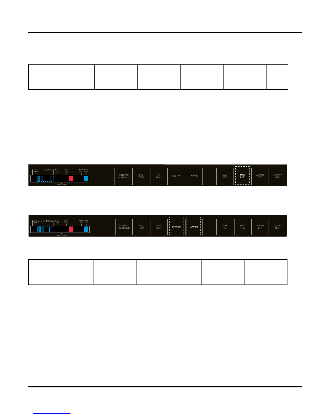
Freezer Cut-In/Out Temperature Differential
Note: Settings should not be changed unless instructed or if they are not correct.
The parameter defines the temperature separation between the freezer cut-in and cut-out temperatures.
Place the unit in Program Mode A (see Program Mode on page 22). Press the “MAX FRZ” pad. An audio
confirmation beep will be heard. The Max Frz indicator will be illuminated. The differential temperature will
be displayed by use of one of the nine temperature indicator bars. The 9th bar is the default setting for the
freezer compartment.
The differential temperature is changed by using the Raise Temp and Lower Temp keys. Pressing the “RAISE
TEMP” key once will change the temperature by one level; pressing the “LOWER TEMP” key once will change
the temperature by one level in the opposite direction.
1 2 3 4 5 6 7 8
3
5 5 6 7 8 9 10 12*
9
The indicator light and corresponding differential temperatures are listed below.
Indicator
Cut-In/Out
Temperature Differential
*Example shown above
© 2010 Viking Preferred Service
1 2 3 4 5 6
3 4 5 6 7 9 11* 13 15
7
8 9
26

Diagnostics
Mode B Functions
Once in Program Mode A (see Program Mode on page 22), press “ACTIVATE CONTROLS” pad to enter
Program Mode B. The orange LED to the right of the HIGH TEMP indicator will turn off and the High Temp
light will turn on. This indicates the controller is in Service Mode B.
Once in Program Mode B, the following programmable functions can be achieved:
UÊÕÌ>ÌVÊiÞL>À`ÊÕVÌÃ
UÊÀÊ>ÀÊi>Þ
UÊ`ÕÃÌÊ8Ê,ÊÀÕÊÌi
UÊ`ÕÃÌÊ8Ê,<ÊÀÕÊÌi
UÊ/i«ÊvvÃiÌÊ>LÀ>Ì
UÊivÀÃÌÊ`iÊÃiiVÌ
Automatic Keyboard Functions
Pressing “DISPLAY OFF” pad toggles between active and inactive keyboard. If high temperature indicator
glows, all pads (keys) except “ALARM OFF” and “ACTIVATE CONTROLS” will be disabled after 10 minutes.
If high temperature indicator is off, all pads (keys) on the keyboard are always enabled. DO NOT LEAVE
KEYBOARD IN ENABLED MODE AFTER PROGRAMMING IS COMPLETE.
© 2010 Viking Preferred Service
27
 Loading...