

Viking VGIC53626BBFLP, VGIC53024BBFLP, VGIC53024BAG, VGIC53024BABLP, VGIC53024BAB Installation Manual
...
Installation
GUIDE
Professional Freestanding Open Burner Gas Ranges
VGIC5302
VGIC5362
1

Table of Contents
Warnings & Important Safety Instructions ..................................................................................................................................................................3
Dimensions .............................................................................................................................................................................................................................4
Speci cations .........................................................................................................................................................................................................................5
Clearance Dimensions (Proximity to Cabinets) .........................................................................................................................................................6
Clearance Dimensions (Wood/Composite Overlay) ................................................................................................................................................7
Electrical & Gas Requirements .........................................................................................................................................................................................8
General Information ............................................................................................................................................................................................................9
Installation ..............................................................................................................................................................................................................................10
Door Removal ...................................................................................................................................................................................................10
Leg Installation .................................................................................................................................................................................................10
Leveling/Adjustments/Alignment .............................................................................................................................................................11
Anti-tip Device Installation
Wall Mount .......................................................................................................................................................................................12
Floor Mount ......................................................................................................................................................................................13
Connecting Gas & Electrical .........................................................................................................................................................................13
Final Installation ............................................................................................................................................................................................... 14
Door Replacement and Adjustment ......................................................................................................................................................... 14
Final Preparation ...................................................................................................................................................................................................................15
Performance Checklist........................................................................................................................................................................................................14
Service & Registration .........................................................................................................................................................................................................15
Your safety and the safety of others is very important.
We have provided many important safety messages in this manual and on your appliance. Always read and obey all safety
messages.
This is the safety alert symbol. This symbol alerts you to hazards that can kill or hurt you and others.
All safety messages will be preceded by the safety alert symbol and the word “DANGER,” “WARNING” or “CAUTION.” These words
mean:
DANGER
Hazards or unsafe practices which WILL
result in death or severe personal injury.
WARNING
Hazards or unsafe practices which COULD
result in death or severe personal injury.
CAUTION
Hazards or unsafe practices which COULD result
in minor personal injury.
All safety messages will identify the hazard, tell
you how to reduce the chance of injury, and tell
you what can happen if the instructions are not
followed.
I f the information in this manual is not
followed exactly, a re or explosion may result
causing property damage, personal injury or
death.
WHAT TO DO IF YOU SMELL GAS:
• DO NOT try to light any appliance.
• DO NOT touch any electrical switch.
• DO NOT use any phone in your building.
• Immediately call your gas supplier from a
neighbor’s phone. Follow the gas supplier’s
instructions.
• If you cannot reach your gas supplier, call
the re department.
Installation and service must be performed by
a quali ed installer, service agency or the gas
supplier.
WARNING
2
Important - Read and Follow!
Before beginning, please read these instructions completely and carefully.
•DO NOT remove permanently a xed labels, warnings, or plates from product. This may void the warranty.
• All local and national codes and ordinances must be observed. Installation must conform with local codes or in the absence of
codes, the National Fuel Gas Code ANSI Z223.1 INFPA54.
•The installer must leave these instructions with the consumer who should retain for local inspector’s use and for future reference.
In Canada: Installation must be in accordance with the current CAN/CGA B149.1 & 2 Gas Installation codes and/or local codes.
Electrical installation must be in accordance with the current CSA C22.1 Canadian Electrical Codes
Part 1 and/or local codes.
In Massachusetts: All gas products must be installed by a “Massachusetts” licensed plumber or gas tter. A “T” type handle manual
valve must be installed in the gas supply line to the appliance.
An air curtain or other overhead range hood which operates by blowing a downward air ow onto the range, shall not be used
with a gas range
A GFI shall be used if required by NFPA-70 (National Electric Code), federal/state/local laws, or local ordinances.
• The required use of a GFI is normally related to the location of a receptacle with respect to any signi cant sources of water or
moisture.
• Viking Range, LLC will NOT warranty any problems resulting from GFI outlets which are not installed properly or do not meet the
requirements below.
If the use of a GFI is required, it should be:
•Of the receptacle type (breaker type or portable type NOT recommended)
•Used with permanent wiring only (temporary or portable wiring NOT recommended)
•On a dedicated circuit (no other receptacles, switches or loads in the circuit)
•Connected to a standard breaker of appropriate size (GFI breaker of the same size NOT recommended)
•Rated for Class A (5 mA +/- 1 mA trip current) as per UL 943 standard
•In good condition and free from any loose- tting gaskets (if applicable in outdoor situations)
•Protected from moisture (water, steam, high humidity) as much as reasonably possible
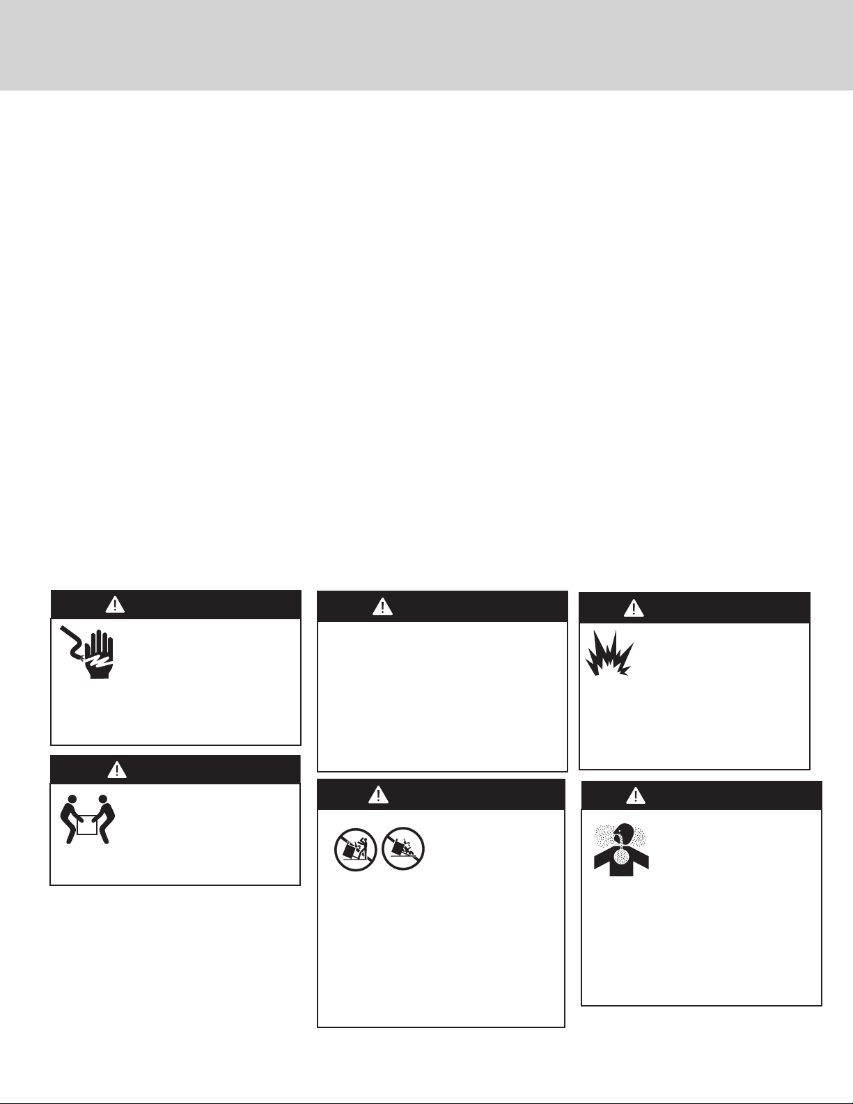
WARNING
ELECTRICAL SHOCK HAZARD
To avoid risk of electrical shock,
personal injury or death; verify
your appliance has been properly
grounded in accordance with local codes or in
absence of codes, with the National Electrical
Code (NEC). ANSI/NFPA 70-latest edition
WARNING
MOVING HAZARD
To avoid risk of severe personal
injury; this appliance requires two
or more personnel while handling
and moving. Possible use of appliance moving
devices is recommended.
WARNING
To prevent possible damage to cabinets
and cabinet nishes, use only materials and
nishes that will not discolor or delaminate
and will withstand temperatures up to 194°F
(90°C). Heat resistant adhesive must be used
if the product is to be installed in laminated
cabinetry. Check with your builder or cabinet
supplier to make sure that the materials meet
these requirements.
WARNING
TIPPING HAZARD
To reduce the risk of
the appliance tipping,
it must be secured by
a properly installed anti-tip bracket(s). To
make sure the bracket has been installed
properly, look behind the range with a
ashlight to verify proper installation
engaged in the rear top left corner of the
range.
• THIS RANGE CAN TIP
• INJURIES TO PERSONS CAN RESULT
• INSTALL ANTITIP DEVICE PACKED
WITH RANGE
• SEE INSTALLATION INSTRUCTIONS
WARNING
GAS LEAK HAZARD
To avoid risk of personal
injury or death; leak testing
of the appliance must be
conducted according to the
manufacturer’s instructions. Before
placing appliance in operation, always
check for gas leaks with soapy water
solution.
• DO NOT USE AN OPEN FLAME TO CHECK
FOR GAS LEAKS
DANGER
CHEMICAL HAZARD
To avoid risk of property
damage and/or personal injury
or death; this appliance is not
too be used as a heating source.
Benzene is a chemical which is part of the
gas supply to this cooking product, which is
consumed in the ames during combustion.
Exposure to a small amount of benzene is
possible if a gas leak occurs. Formaldehyde
and soot are by-products of incomplete
combustion.
3

Dimensions
35-7/8”
(91.1 cm)
29-7/8”
(75.9 cm)
30” AND 36” W. RANGES
1”
(2.5 cm)
35-7/8”
(91.1 cm) min.
to
(94.0 cm) max.
37”
8-1/8”
(20.6 cm)
19-3/8”
(49.2 cm)
28-1/16” (71.2 cm)
1-5/8”
(4.1 cm)
26-7/16” (67.2 cm)
1” (2.5 cm)
35-7/8”
(91.1 cm) min.
to
37”
(94.0 cm) max.
25-3/4” (65.4 cm)
45-1/8” (114.6 cm)
24-5/16” (61.8 cm)
NOTE: Unit shown with standard island trim
4

Speci cations
Description 30” W. (76 cm) Wide 36” W. (91 cm) Wide
Overall width 29-7/8” (75.9 cm) 35-7/8” (91.1)
Overall height from bottom
To top of side panl
Leg adjustment
Overall depth from rear
To end of side panel
To front of door
To end of landing ledge
To end of door handle
Additions to Base Height To top of island trim: add 1” (2.5 cm)
Gas requirements Shipped Natural or LP/Propane, accepts standard residential 1/2” (1.3 cm) ID gas
Electrical equirements 120VAC/60 Hz; 4 ft. (121.9 cm), 3-wire cord with grounded
Maximum amp usage .83 amps 1.5 amps
Surface Burners Natural/LP
Broil Burner Natural/LP
Oven Burner Natural/LP
Oven interior width 23” (58.4 cm) 29” (73.7 cm)
Oven interior height 16-1/8” (40.9 cm)
Oven interior depth Overall - 18-3/4” (47.6 cm)
Oven volume
Overall
AHAM
Approximate shipping weight 410 lbs.
35-7/8” (91.1 cm) min to 37” (94.0 cm) max
1-1/8” (2.9 cm)
24-5/16” (61.8 cm)
25-3/4” (65.4 cm)
28-1/16” (71.2 cm)
28-11/16” (72.9 cm)
*Add 3/4” (1.9 mc) to overall depth for ranges with a backguard or high shelf to allow for
rear spacers when installed against a combustible wall.
To top of backguard - add 8” (20.3 cm)
To top of high shelf - add 23-1/2” (59.7 cm)
service line. Unit is eld convertible with proper conversion kit
3-prong plug attached to unit
15
,000 BTU (4.4 kW)/13,500 BTU (4.3 kW)
18,000 BTU (5.3 kW)/16,000 BTU (4.7 kW)
30,000 BTU (8.8 kW) Nat./LP
4.0 cu. ft.
3.7 cu. ft.
(184.5 kg)
5.1 cu. ft.
5.1 cu. ft.
500 lbs.
(225 kg
Minimum clearances from adjacent combustible construction:
Below cooking surface (36” [91.4 cm] and below)
• Sides - 0”
• Top grate support - 36” (91.4 cm)
Above cooking surface (above 36” [91.4 cm])
• Sides - 8” (20.3 cm)
• Within 8” (20.3 cm) side clearance, wall cabinets no deeper than 13” (33.0 cm) must be minimum 18” (45.7 cm) above
cooking surface
• Wall cabinets directly above product must be a minimum of 42” (106.7 cm) above cooking surface
• Rear - 3/4” (1.9 cm) with 8” backguard or high shelf to allow for rear spacers against a combustible rear wall;
• 6” (15.2 cm) with island trim against combustible rear wall
5
 Loading...