

Viking VESO5271, VEDO5271, VEDO5272, VESO5301, VESO5302 Service Manual
...
Service
Manual
This manual is to be used by qualied appliance technicians only. Viking
does not assume any responsibility for property damage or personal
injury for improper service procedures done by an unqualied person.
Preferred Service
Built-In Electric
Wall Ovens
This Base Manual covers general and
specic information including, but not
limited to the following models:
VESO5271
VESO5272
VEDO5271
VEDO5272
VESO5301
VESO5302
VEDO5301
VEDO5302
SMC-0034
APRIL 2013

Table of Contents
Important Information ..................................................... 3
Safety Information .................................................... 3
General Information ........................................................ 4
Serial Number .......................................................... 4
Operation ................................................................. 5
Oven Control Panel .............................................. 5
Setting the Clock ...................................................... 6
Digital Display (Select Models) ............................. 6
Analog Display (Premiere Models) ....................... 6
Built-In Electric Oven Features ................................ 7
Oven Settings and Functions ................................... 7
Clocks and Timers (Digital Display) ......................... 9
Clocks and Timers (Analog Clock) ......................... 10
Self-Clean Cycle .....................................................11
Troubleshooting ............................................................ 13
Parts Location – Control Board .............................. 13
Control Board Test Points ...................................... 14
Control Board Diagnosis ........................................ 15
Line Break Relay ................................................ 15
Bake Element ..................................................... 15
Bake Relay (Inner and Outer) ............................. 16
Inner Bake Relay ................................................ 16
Outer Bake Relay ............................................... 16
Broil Element ...................................................... 16
Broil Relay (Inner and Outer) .............................. 17
Inner Broil Relay ................................................. 17
Outer Broil Relay ................................................ 17
Convection Element ............................................ 17
Convection Relay ................................................ 18
Cooling Fan ........................................................ 18
Cooling Fan Relay .............................................. 18
Convection Fan ................................................... 19
Convection Operation ......................................... 19
Testing Control Board ......................................... 20
Testing The Capacitors ....................................... 20
Testing Fan Motor ............................................... 20
Door Lock Assembly ........................................... 21
Testing Lock Motor .............................................. 21
Testing Latch Switches ....................................... 21
Checking the door lock position switches ........... 22
RTD Sensor ........................................................ 23
RTD Characteristics ............................................ 23
Selector and Thermostat Characteristics ............... 24
Troubleshooting Guide ........................................... 25
LED Error Codes .................................................... 27
Disassembly ................................................................. 28
Parts Location ........................................................ 28
Oven Rack Removal .............................................. 29
Glide Rack .......................................................... 29
Standard Rack .................................................... 29
Door Assembly Removal ........................................ 29
Partial Oven Removal ............................................ 30
Complete Oven Removal ....................................... 30
Door Gasket Removal ............................................ 31
Door Handle Removal ............................................ 31
Outer Door Panel Assembly Removal ................... 31
Outer Door Glass Removal .................................... 32
Inner Door Glass Removal ..................................... 33
Door Hinge Removal .............................................. 33
Door Logo Removal ............................................... 33
Oven Rack Support Removal ................................ 34
Oven Light Bulb Removal ...................................... 34
Top Light ............................................................. 34
Side Lights .......................................................... 34
RTD Sensor Removal ............................................ 34
Broil Element Removal .......................................... 35
Bake Element Removal ......................................... 35
Convection Bafe Removal .................................... 36
Catalyst Removal ................................................... 36
Convection Bake Element Removal ...................... 37
Convection Fan Motor Removal ............................ 37
Convection Fan Blade Removal ............................ 38
Access to Control Components ............................. 38
Control Panel Access .......................................... 38
Partial Control Board Area Access ...................... 38
Complete Control Board Area Access ................ 39
Oven Function Selector Removal .......................... 39
Oven Thermostat Removal .................................... 39
Oven Light Switch Removal ................................... 39
Oven Cycle/Clean Indicator Lights Removal ......... 40
Timed Bake Switch Removal ................................. 40
Oven Timer/Clock Removal ................................... 40
Oven Control Board Removal ................................ 41
Convection Motor Capacitors Removal ................. 41
Thermal Cut-Out (TCO) Removal .......................... 42
Single Oven and Upper Double Oven ................ 42
Lower Double Oven ............................................ 42
Door Latch Assembly Removal .............................. 42
Single Oven and Upper Double Oven ................ 42
Lower Double Oven ............................................ 43
Door Switch Removal ............................................ 43
Single Oven and Upper Double Oven ................ 43
Lower Double Oven ............................................ 43
Blower Motor .......................................................... 43
Single Oven and Upper Double Oven ................ 43
Lower Double Oven ............................................ 44
Door Hinge Receiver Removal .............................. 45
Meat Probe Socket Removal ................................. 45
Wiring Diagrams ........................................................... 46
Wiring Diagrams .................................................... 46
2 ©2013 Viking Preferred Service

Important Information
SAVE THESE INSTRUCTIONS
REVIEW ALL SERVICE INFORMATION IN THE APPROPRIATE SERVICE MANUAL AND TECHNICAL SHEETS
BEFORE BEGINNING REPAIRS.
Pride and workmanship go into every product to provide our customers with quality products. It is possible, however,
that during its lifetime, a product may require service. Products should be serviced only by a qualified service
technician that is familiar with the safety procedures required in the repair and who is equipped with the proper tools,
parts, testing instruments, and the appropriate service manual.
Safety Information
We have provided many important safety messages in
this manual and on the appliance. ALWAYS read and
obey all safety messages. This is the safety alert symbol.
This symbol alerts you to hazards that can kill or hurt
you and others. All safety messages will be preceded
by the safety alert symbol and the word “DANGER”,
“WARNING”, or “CAUTION”. These words mean:
IMMEDIATE HAZARDS WHICH WILL RESULT IN
SEVERE PERSONAL INJURY OR DEATH.
Hazards or unsafe practices which COULD result in
severe personal injury or death.
All safety messages will identify the hazard, tell you how
to reduce the chance of injury, and tell you what can
happen if the instructions are not followed.
To avoid risk of serious injury or death, repairs should
not be attempted by unauthorized personnel.
VIKING will not be responsible for any injury or
property damage from improper service procedures.
If performing service on your own product, you must
assume responsibility for any personal injury or
property damage which may result.
To locate an authorized servicer, call:
Viking Customer Service
Phone No. 1-888-845-4641
Address your written correspondence to:
Hazards or unsafe practices which COULD result in
minor personal injury or product or property damage.
©2013 Viking Preferred Service 3
Viking Preferred Service
1803 HWY 82 West
Greenwood, MS 38930
General Information
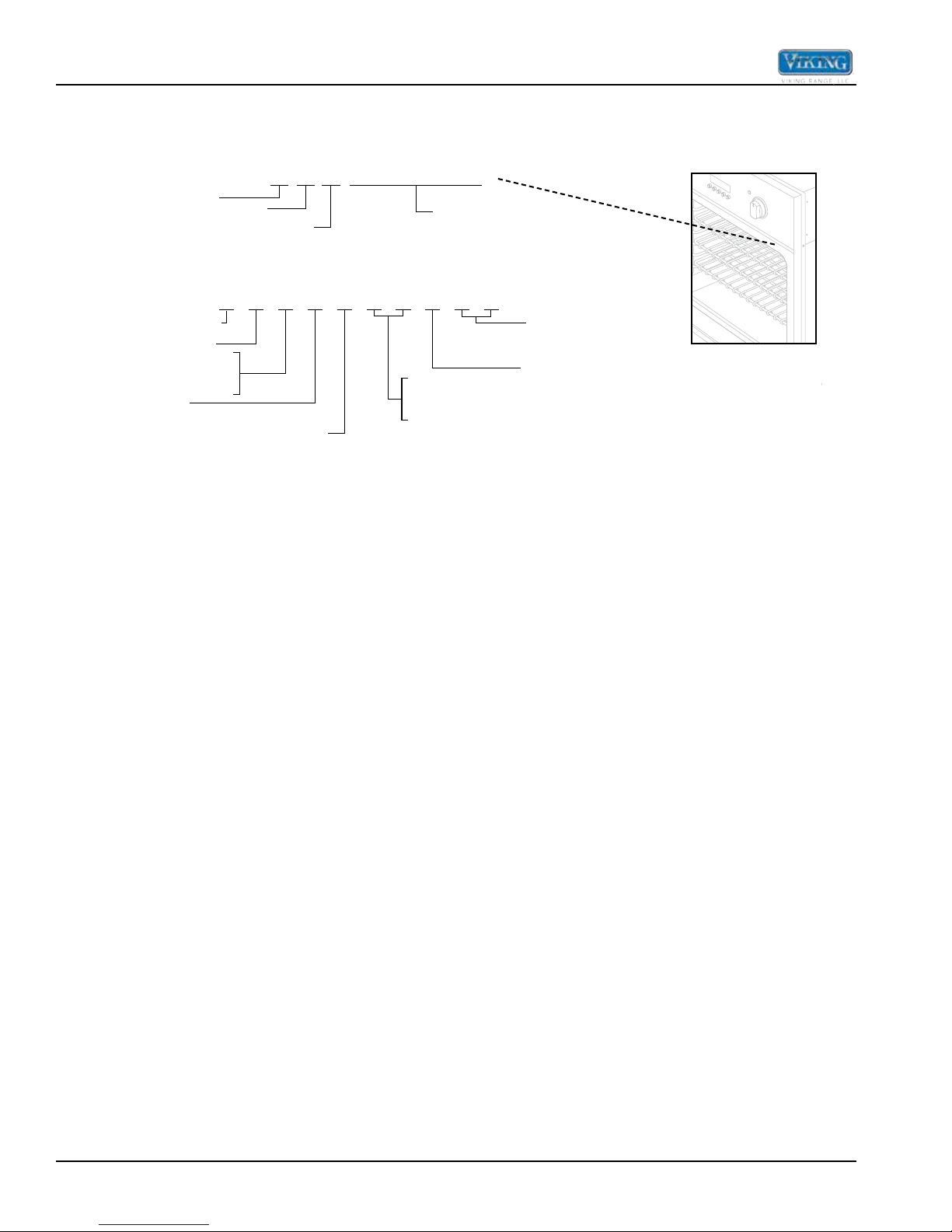
Model Number
Serial Number
The serial number and model number for your appliance can be found by opening the door and looking under the
control panel on the right side.
Serial Number 011811C0000000001
Month
Year of Manufacture
V = Professional
E = Electric
S = Single
D = Double
O = Oven
Day
V
E SO5 3 0
5 = Premiere
Serial Number
2 S S
SS = Stainless
2 = Series
27 = 27" Wide
30 = 30" Wide
4 ©2013 Viking Preferred Service
General Information
Interior Oven
Light Switch
Analog Clock with Digital Display
Interior Oven
Light Switch
Analog Clock with Digital Display
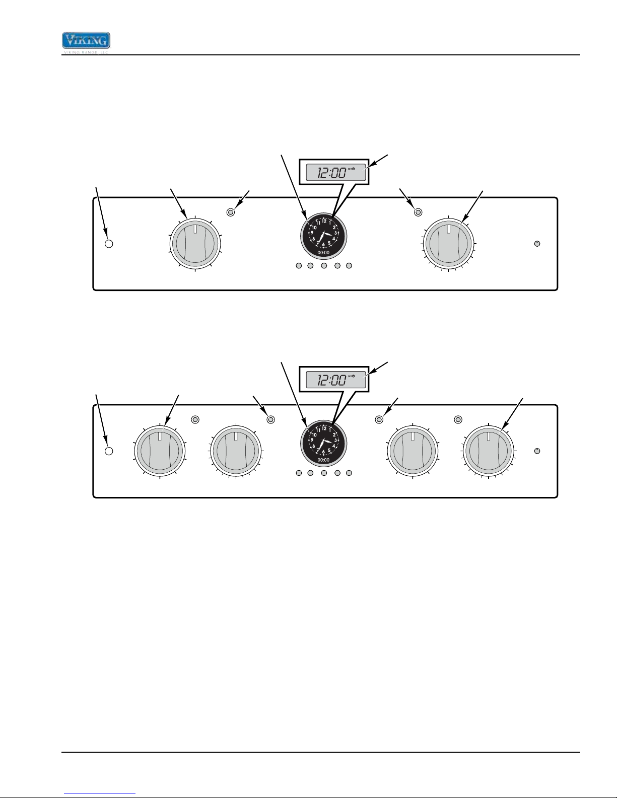
Operation
Oven Control Panel
The Viking Built-In Electric Wall Ovens are available in two control panel options. Each oven has a Function Selector
and a Temperature Control. On double ovens, the Interior Oven Light Switch and Electronic Timing Center are
shared.
OVEN
LIGHT
OVEN
LIGHT
Oven Function
SELF
CLEAN
LOW
BROIL
MED
BROIL
HI
BROIL
OVEN FUNCTION
Selector
SELF
CLEAN
LOW
BROIL
MED
BROIL
HI
BROIL
OVEN FUNCTION
Self-Clean Indicator
OFF
BAKE
CONV.
BROIL
Oven Function
Selector
BAKE
ROAST
CONV.
CLEAN
CONV.
BAKE
TRU
CONVEC
UPPER OVEN
200
300
OVEN TEMPERATURE
OFF
CONV.
BROIL
(Premiere Models)
CLEAN
CONV.
BAKE
TRU
CONVEC
CONV.
ROAST
(Premiere Models)
Off/On Indicator
OFF
400
OVEN
CLEAN
BROIL
500
min/sec
bake
start
Set
timer
time
time
Single Oven
min/sec
bake
start
Set
timer
time
time
Digital Clock
(Select Models)
Temperature
Off/On Indicator
OVEN
probe
temp
OFF
200
300
400
OVEN TEMPERATURE
Control
CLEAN
BROIL
500
timed
manual
Digital Clock
(Select Models)
Temperature
Self-Clean Indicator
CLEAN
LOW
BROIL
MED
BROIL
probe
temp
SELF
CLEAN
HI
BROIL
OVEN FUNCTION
OFF
CONV.
BROIL
BAKE
ROAST
CONV.
CONV.
BAKE
TRU
CONVEC
LOWER OVEN
OVEN
200
300
OVEN TEMPERATURE
OFF
400
Control
CLEAN
BROIL
500
upper
timed
lower
timed
manual
©2013 Viking Preferred Service 5
Double Oven

General Information
min/sec
timer
time
time
probe
temp
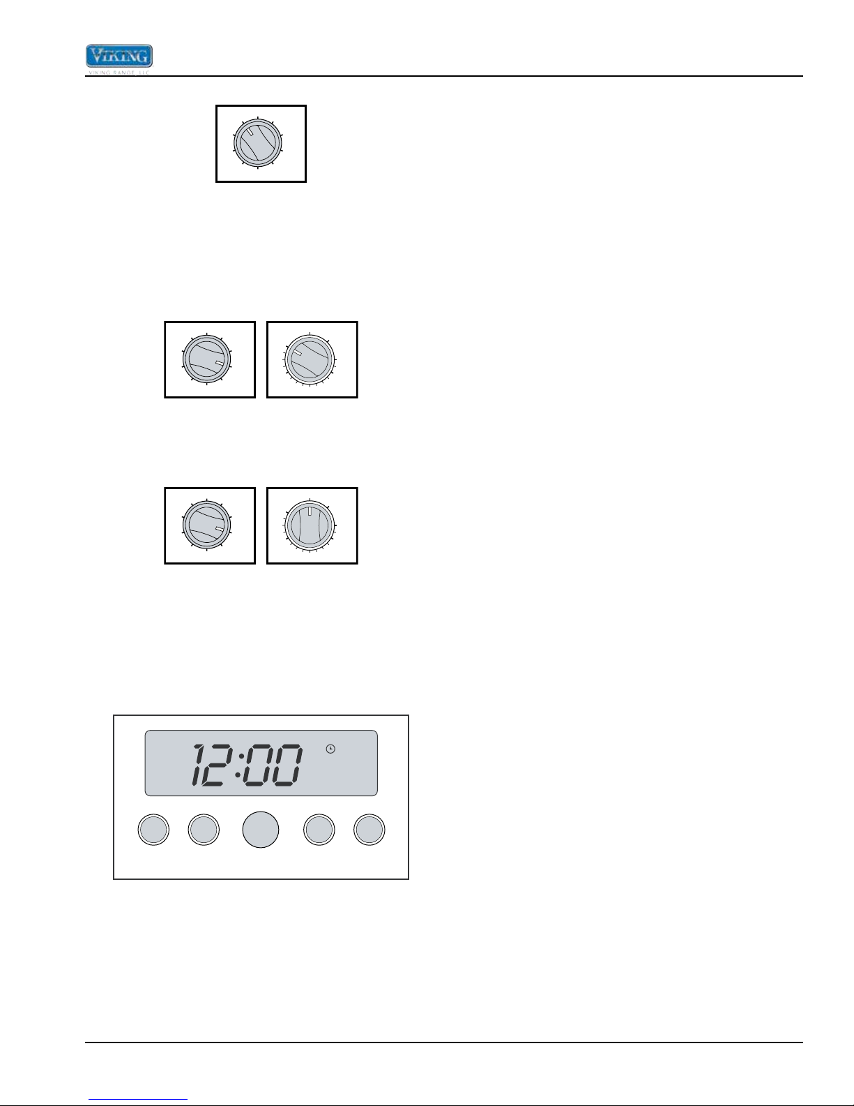
Setting the Clock
Digital Display (Select Models)
The time-of-day must be set before any other program
can be used. When your oven is first connected to the
power in your home, the timer display will show --:--.
SET
CLOCK MIN/SEC
TIMER
SET
To program the time-of-day:
1. Press the “CLOCK”* button once. 12:00 will be
displayed with the word SET in the upper right
corner.
2. Turn the “SET” knob until the correct time-of-day is
displayed. AM and PM are not indicated.
3. Press the “CLOCK” button again. The word SET will
disappear and the correct time is now set into the
timer. The time-of-day can be changed by following
steps 1 through 3. It cannot be changed while there
is a Bake Hours or Start Time cycle programmed into
the timer.
*NOTE: The PROBE function is included on Premiere
Models.
BAKE
TIME
START
TIME
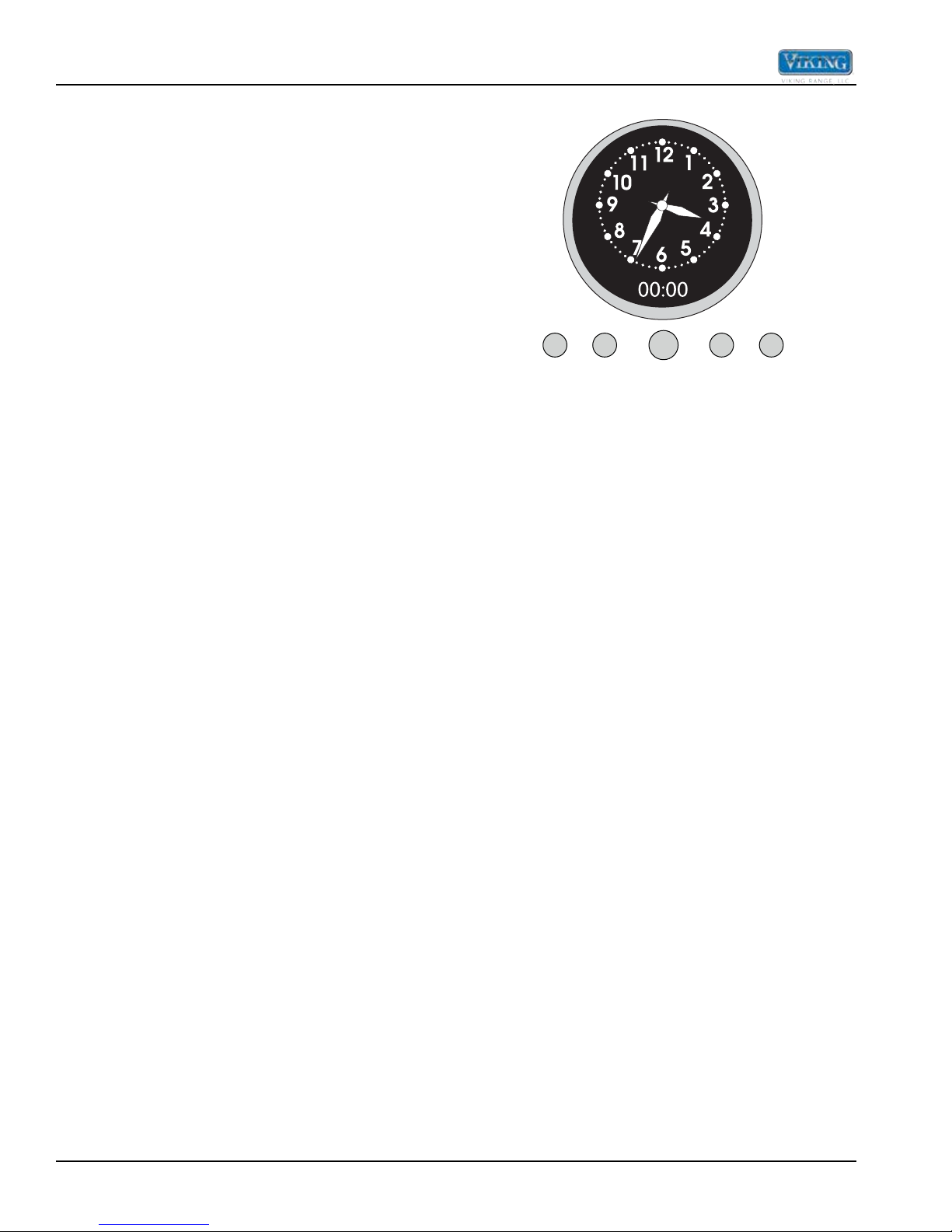
Analog Display (Premiere Models)
Synchronizing the analog and digital clocks:
bake
Set
start
NOTE: It is important to always synchronize the analog
and digital clocks before setting the timeof- day.
1. Press and release the “start time” button.
NOTE: This is only necessary after a power outage or
for the rst time to set the clock.
2. Press and hold the “min/sec timer” and start time
buttons simultaneously.
3. Turn the “Set” knob to move the hands on the analog
clock to 30 minutes ahead of the current time.
Release hold from “start time” and “min/sec timer”
buttons.
4. After several seconds, the display will blink. Press
and hold the “min/sec timer” button and turn the “Set”
knob to set the digital clock so that it matches exactly
with the analog clock. The clocks are now synched
and you can now set the time of day. The time-of-day
must be set before any other program can be used.
6 ©2013 Viking Preferred Service
Setting the time-of-day:
1. Push and hold the “min/sec timer” and “bake time”
buttons simultaneously.
2. Turn the “Set” knob until correct time is displayed on
the digital clock.
3. Release hold from “min/sec timer” and “bake time”
buttons. The analog clock’s time will automatically
set to match the digital clock.
Built-In Electric Oven Features
(u
t
Premiere Professional double oven is shown above.
two-element bake
TruConvec
Model/Serial
Number Plate
nder control pane l)
General Information
CLEAN OVEN CLEAN OVEN
CLEANOVENCLEAN OVEN
OFF
OFF
SELF
SELF
CLEAN
CLEAN
OFF
OFF
SELF
SELF
CLEAN
CLEAN
OVEN
OVEN
LOW
LOW
LIGHT
LIGHT
BROIL
BROIL
UPPER TIMED
UPPER TIMED
CONV.
CONV.
BROIL
BROIL
MANUAL
MANUAL
MED
MED
LOWER TIMED
LOWER TIMED
BROIL
BROIL
MAXI
MAXI
BROIL
BROIL
MINI
MINI
BROIL
BROIL
HI
HI
BROIL
BROIL
CONV.
CONV.
BROIL
BROIL
OVEN FUNCTION
OVEN FUNCTION
OFF
OFF
OVENCLEAN
BAKE
BAKE
CONVEC
OVENCLEAN
OFF
OFF
CLEAN
BAKE
BAKE
CONV.
CONVEC
BAKE
CONV.
CONV.
BAKE
BAKE
TRU
CONV.
CONVEC
TRU
TRU
BAKE
CONVEC
UPPER OVEN
UPPER OVEN
CONV.
CONV.
ROAST
ROAST
UPPER OVEN
UPPER OVEN
CLEAN
CLEAN
CLEAN
200
200
TRU
TEMPERATUREOVEN FUNCTION
TEMPERATUREOVEN FUNCTION
300
300
BROIL
BROIL
400
400
TEMPERATURE
OVEN TEMPERATURE
BROIL
BROIL
500
500
BAKE
MIN/SEC
SET
TIME
TIMER
OFF
OFF
SELF
SELF
CLEAN
CLEAN
SELF
SELF
SELF
SELF
CLEAN
CLEAN
CLEAN
CLEAN
LOW
LOW
BROIL
BROIL
CONV.
CONV.
CONV.
CONV.
BROIL
BROIL
BROIL
BROIL
SET
SET
MED
MED
BROIL
BROIL
MAXI
MAXI
MAXI
MAXI
BROIL
BROIL
BROIL
BROIL
HI
HI
BROIL
BROIL
CONV.
CONV.
BROIL
BROIL
START
PROBE
OVEN FUNCTION
OVEN FUNCTION
TIME
TEMP
OFF
OFF
OVENCLEAN
OVENCLEAN
OVENCLEAN
OVENCLEAN
BAKE
BAKE
OFF
OFF
OFF
OFF
OFF
OFF
OFF
OFF
CONV.
CONVEC
BAKE
TRU
CONV.
CONVEC
BAKE
MINI
MINI
MINI
MINI
BROIL
BROIL
BROIL
BROIL
CONV.
CONV.
ROAS
ROAST
T
TRU
LOWER OVEN
LOWER OVEN
CLEAN
CLEAN
UPPER OVEN LIGHT
TRU
TRU
TRU
TRU
CONV.
CONV.
CONV.
CONV.
BAKE
BAKE
BAKE
BAKE
LOWER OVEN
LOWER OVEN
LOWER OVEN
LOWER OVEN
200
200
200
200
300
300
300
300
400
400
500
500
TEMPERATUREOVEN FUNCTION
TEMPERATUREOVEN FUNCTION
TEMPERATUREOVEN FUNCTION
TEMPERATUREOVEN FUNCTION
400
400
TEMPERATURE
OVEN TEMPERATURE
UPPER OVEN LIGHT
CLEAN
CLEAN
CLEAN
CLEAN
UPPER
TIMED
BROIL
BROIL
L
MANUA
LOWER OVEN LIGHT
LOWER OVEN LIGHT
LOWER
TIMED
500
500
BROIL
BROIL
BROIL
BROIL
BAKE
BAKE
BAKE
BAKE
CONVEC
CONVEC
CONVEC
CONVEC
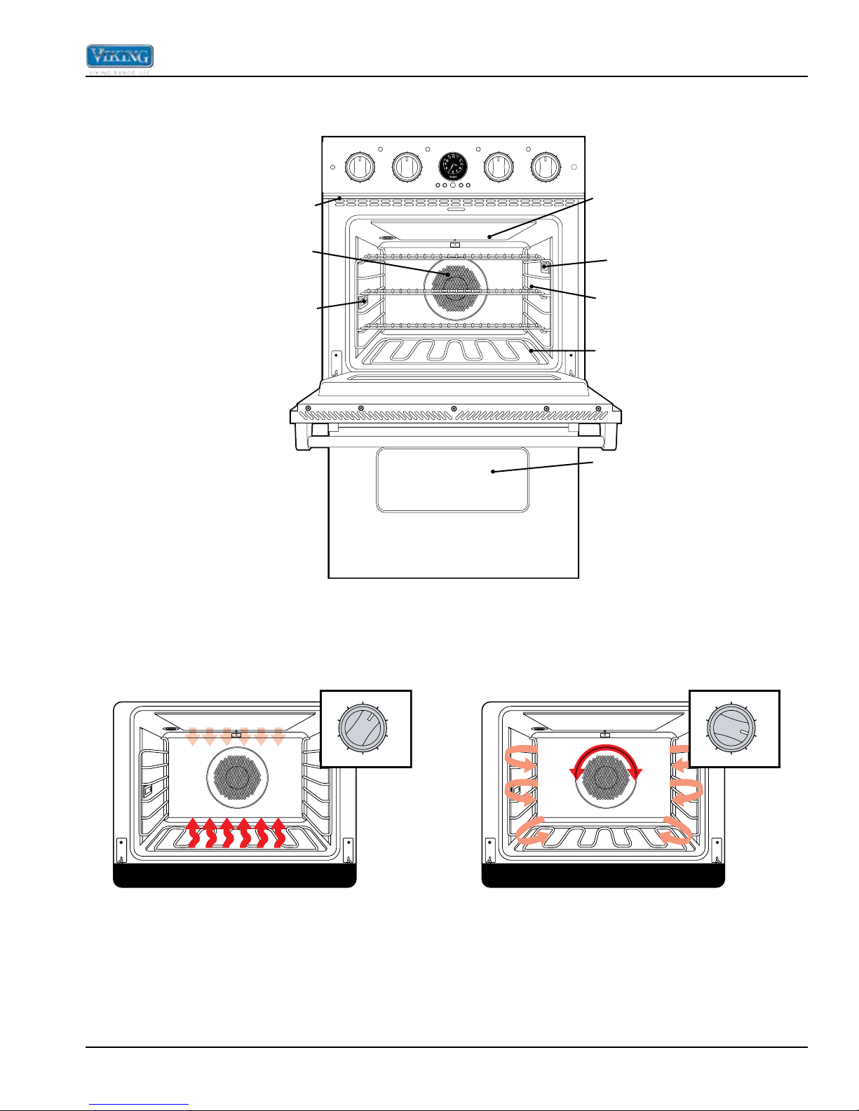
Broil Element
TruConvec™
Element
(Behind Baffle)
Oven Light
Oven Settings and Functions
Oven Light
Oven Racks
(3/upper oven;
3/lower oven)
Bake Elemen
Lower Oven
Two-Element Bake
OFF
SELF
CLEAN
LOW
BROIL
BROIL
MED
BROIL
BAKE
CONV.
BAKE
TRU
CONVEC
CONV.
HI
ROAST
CONV.
BROIL
TruConvec
BROIL
LOW
MED
BROIL
SELF
CLEAN
BROIL
OFF
BAKE
CONV.
BAKE
TRU
CONVEC
CONV.
HI
ROAST
CONV.
BROIL
The bake elements use approximately 240V and the
inner broil element cycles on and off at various times to
maintain the set temperature.
The convection element uses approximately 240V and
pulses on and off. The convection fan remains in low
speed and changes direction.
©2013 Viking Preferred Service 7
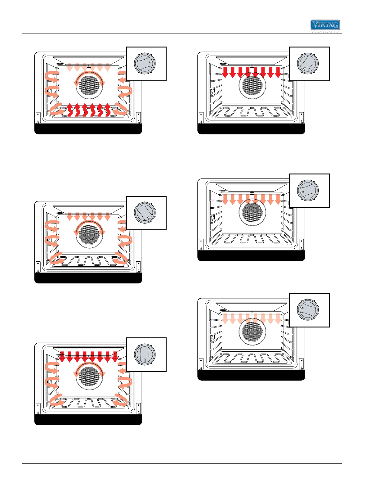
General Information
convection bake
convection roast
convection broil
high broil
medium broil
low broil
Convection Bake
OFF
SELF
LOW
BROIL
BROIL
CLEAN
MED
BROIL
BAKE
CONV.
BAKE
TRU
CONVEC
CONV.
HI
ROAST
CONV.
BROIL
The convection element uses approximately 240V and
cycles on and off at various times. The bake and broil
elements use 240V and pulse on and off less frequently
than the convection element. Additionally, the convection
fan cycles on and off, and then cycles on in the opposite
direction. This cycle then repeats.
Convection Roast
OFF
SELF
LOW
BROIL
BROIL
CLEAN
MED
BROIL
BAKE
CONV.
BAKE
TRU
CONVEC
CONV.
HI
ROAST
CONV.
BROIL
High Broil
OFF
SELF
BROIL
LOW
MED
BROIL
CLEAN
BROIL
BAKE
CONV.
HI
ROAST
CONV.
BROIL
Heat radiates from both broil elements. The broil
elements use approximately 240V and remain on
constantly.
Medium Broil
OFF
SELF
BROIL
LOW
MED
BROIL
CLEAN
BROIL
BAKE
CONV.
HI
ROAST
CONV.
BROIL
CONV.
BAKE
TRU
CONVEC
CONV.
BAKE
TRU
CONVEC
The convection element uses approximately 240V and
pulses on and off. The convection fan remains in high
speed and changes direction. During the change in
direction, the broil elements pulse on and off for a few
seconds.
Convection Broil
OFF
SELF
LOW
BROIL
BROIL
CLEAN
MED
BROIL
BAKE
CONV.
BAKE
TRU
CONVEC
CONV.
HI
ROAST
CONV.
BROIL
Heat radiates from both broil elements. The broil
elements use approximately 240V and pulse on and off.
Additionally, the convection fan cycles on and off, and
then changes direction. This cycle then repeats.
Heat radiates from both broil elements. The broil
elements use approximately 240V and pulse on and off.
Low Broil
OFF
SELF
BROIL
LOW
MED
BROIL
CLEAN
BROIL
BAKE
CONV.
BAKE
TRU
CONVEC
CONV.
HI
ROAST
CONV.
BROIL
Heat radiates only from the inner broil element. The
inner broil element uses approximately 240V and pulses
on and off.
8 ©2013 Viking Preferred Service
General Information
Self-Clean
OFF
SELF
LOW
BROIL
MED
BROIL
CLEAN
BROIL
BAKE
CONV.
BAKE
TRU
CONVEC
CONV.
HI
ROAST
CONV.
BROIL
During the self-clean cycle, the oven reaches elevated
temperatures using the broil and bake elements. The
broil elements use approximately 240V and remain
on during the self-clean cycle. The bake elements use
approximately 240V and cycle on for a few seconds at
various times during the cleaning process.
Convection Dehydrate
LOW
BROIL
BROIL
OFF
SELF
CLEAN
MED
BROIL
BAKE
CONV.
BAKE
TRU
CONVEC
CONV.
HI
ROAST
CONV.
BROIL
OFF
200
300
CLEAN
BROIL
500
400
With the selector set to TruConvec and the temperature
control on 200°F, warm air is circulated by the convection
fan.
Convection Defrost
LOW
BROIL
BROIL
OFF
SELF
CLEAN
MED
BROIL
BAKE
CONV.
BAKE
TRU
CONVEC
CONV.
HI
ROAST
CONV.
BROIL
OFF
200
300
CLEAN
BROIL
500
400
Only the convection fan operates. No elements are on.
The convection fan cycles on in one direction for a time,
cycles off, and then cycles on in the opposite direction.
This cycle then repeats.
Clocks and Timers (Digital Display)
Electronic Timing Center Digital Display (Select
Models)
SET
off automatically when the timed program is over. For
example, you can time bake a casserole in the upper
oven using the Bake Hours mode, while broiling in the
lower oven using the Min/Sec Timer. One oven can also
be cleaned while timing foods in the other oven using the
Min/Sec Timer.
Setting the Min/Sec Timer
The Min/Sec Timer is designed for accurate timing and is
ideal for baking delicate items such as biscuits, cookies,
and popovers, and for precise broiling. The Min/Sec
Timer can be used at the same time the Bake Hours
or Start Time functions are in use. It can be used for
timing up to 24 hours. When setting the timer, the time
displayed will increase in 1 minute increments. When
the timer counts down to 1 minute, the timer alarm will
give two short beeps and the display changes from
hours:minutes to seconds only.
To program the Min/Sec Timer
1. Press the “MIN/SEC TIMER” button. The timer will
display :00 and the word TIMER will be displayed in
the lower right corner.
2. Turn the “SET” knob until the desired duration time is
displayed.
The Min/Sec Timer is now programmed. The alarm will
sound at the end of the countdown. The program can be
cancelled anytime by setting the remaining time to :00.
To change back to the time-ofday, press the “CLOCK”
button. Notice that a small clock will be displayed in
the upper right corner to indicate that a program is in
progress. The display will return automatically to the Min/
Sec Timer after a few seconds.
Timer Alarm
At the end of a Min/Sec Timer program or Bake
Hours program, the alarm will consist of three beeps
followed by two beeps every 10 seconds until the “MIN/
SEC TIMER” button is pressed. Whenever a valid
function key is pressed or when a control function
starts automatically, one beep will be sounded. When
an invalid function key is pressed, two beeps will be
sounded.
CLOCK MIN/SEC
TIMER
SET
The Electronic Timing Center is used to program and
control all timing functions. It has five display and
programming modes that are activated by the four
push buttons and the “SET” knob. Both the Bake Hours
mode and the Min/Sec Timer mode can be used to time
cooking periods. These features can even be used at
the same time when both ovens are in use. However,
only Bake Hours and Self-Cleaning modes shut the oven
©2013 Viking Preferred Service 9
BAKE
TIME
START
TIME
Setting the Automatic Start Time Bake Program
The Bake Hours and Start Time modes of the timer can
be used to automatically turn the oven on and off at a
preselected time. The Automatic Time Bake program is
ideal for foods with no danger of spoilage during the time
the oven is left off.
To Set The Automatic Time Bake Program:
1. Set the start time:
A) For Single Ovens – Program the start time by
pressing the “START TIME” button and turning the
“SET” knob until the desired start time is displayed.
This is the time of day you want the food to begin
cooking.
General Information
min/sec
timer
time
time
probe
temp
B) For Double Ovens – Press the “START TIME”
button once to set the starting time for the upper
oven (UPPER OVEN will show on the display). Press
the “START TIME” button twice to set the starting
time for the lower oven (LOWER OVEN will show
on the display). Then program the start time by
turning the “SET” knob until the desired start time is
displayed. This is the time of day you want the food
to begin cooking.
2. Set the desired baking time:
Once the start time is set, the display will switch to
:00 and the words SET, COOK and TIME will appear
on the right side of the display. You will now enter
the desired baking time. Turn the “SET” knob until
the desired baking time is displayed in hours and
minutes. Once the desired bake time is set, the word
SET will disappear and the word DELAY will appear
in the display indicating that the Bake Hours program
has been set.
NOTE: For Double Ovens, the word DELAY will show
with either UPPER OVEN or LOWER OVEN
depending on which oven has been selected.
3. Set the Oven Function selector to the desired
function – BAKE, CONVECTION BAKE, OR
TRUCONVEC™, etc.
4. Set the temperature control knob to the desired
baking temperature.
5. The automatic time bake program is now set!
NOTE: The display will continue to show the amount of
bake time that was programmed (this will remain
until the programmed start time is reached). You
can return the display to clock mode by pressing
the “CLOCK” button – Notice that a small clock
will be displayed in the upper right corner to
indicate that a program is in progress. Switch
back to the timer mode by pressing the “BAKE
HOURS” button.
6. When the specified time is reached, the oven will
automatically turn on. It will bake for the programmed
amount of time at the selected temperature.
NOTE: At one minute from the end of the specied bake
program, the oven timer will beep once. At the
end of the specied bake program, the oven will
automatically turn off and the timer will sound a
series of three beeps. This will continue until the
“START TIME” button is pressed. The display
will then return to displaying the time.
NOTE: Setting the remaining duration time to :00 will
cancel the Automatic Bake program.
Clocks and Timers (Analog Clock)
bake
Set
Setting the Min/Sec Timer
The Min/Sec Timer is designed for accurate timing and is
ideal for baking delicate items such as biscuits, cookies,
and popovers, and for precise broiling. The Min/Sec
timer can be used at the same time the Bake Hours or
Start Time functions are in use. It can be used for timing
up to 24 hours.
To program the Min/SecTimer
1. Push and release the “min/sec timer” button.
2. Rotate “Set” knob until desired duration of time is
displayed. Timer starts seconds after “Set” knob
stops rotating. A tone indicates the timer has started.
When the timer has one minute remaining, the timer will
sound twice and begin to countdown by seconds. A tone
will sound three times indicating the time is complete
and twice every ten seconds after completion until timer
function is cleared.
NOTE: Press any function button to clear a completed
cycle or function.
Setting the Bake Hours Program
The Bake Hours program is used for controlled timing
of baked or roasted foods. At the end of the timed cycle,
the oven automatically turns off.
Setting the Automatic Start Time Bake Program
The Bake Hours program is used for controlled timing
of baked or roasted foods. At the end of the timed cycle,
the oven automatically turns off.
To Set The Bake Hours Program
1. Turn the TIMED BAKE knob to “timed” for single
ovens or “upper timed” or “lower timed” position, for
double ovens.
2. Set the Oven Function Selector to the BAKE,
CONVECTION BAKE, or TRUCONVEC™ position,
depending upon the type of baking being used.
3. Set the temperature control knob to the desired
temperature and allow for preheating.
start
10 ©2013 Viking Preferred Service
General Information
4. Press and release the bake hours button. The timer
will display :00 with the words SET and COOK/TIME
in the digital display.
5. Turn the “Set” knob until the desired baking time is
displayed in hours and minutes. Once set, a tone
will sound and the cook time/remaining time and the
word COOK will be displayed.
The word COOK will flash and the tone will sound three
times when the time is completed; oven will turn off. The
tone will sound twice every ten seconds after completion
until timer function is cleared.
To set the Automatic Time Bake Program
1. Set the start time:
A) For Single Ovens – Turn the TIMED BAKE knob
to “timed”. Program the start time by pressing the
“start time” button and turning the “Set” knob until the
desired start time is displayed and a tone is heard.
This is the time of day you want the food to begin
cooking.
B) For Double Ovens – (Press the “start time” button
once to set the starting time for the upper oven.
Press the “start time” button twice to set the starting
time for the lower oven). Then program the start time
by turning the “Set” knob until the desired start time
is displayed. This is the time of day you want the
food to begin cooking.
2. Set the desired baking time:
Once the start time is set, the display will switch to
:00 and the words SET, COOK and TIME will appear
on the right side of the display. You will now enter
the desired baking time. Turn the “Set” knob until
the desired baking time is displayed in hours and
minutes. Once the desired bake time is set, a tone
will be heard and the word SET will disappear and
the word DELAY will appear in the display indicating
that the Bake Hours program has been set.
NOTE: For Double Ovens, the word DELAY will show
depending on which oven has been selected.
3. Set the Oven Function selector to the desired
function – BAKE, CONVECTION BAKE, OR
TRUCONVEC™, etc.
4. Set the temperature control knob to the desired
baking temperature.
5. The automatic time bake program is now set!
NOTE: The display will continue to show the amount of
bake time that was programmed (this will remain
until the programmed start time is reached). You
can return the display to clock mode by pressing
the “probe/temp” button – Notice that a small
clock will be displayed in the upper right corner
to indicate that a program is in progress. Switch
back to the timer mode by pressing the “bake
hours” button.
6. When the specified time is reached, the oven will
automatically turn on. It will bake for the programmed
amount of time at the selected temperature.
NOTE: At one minute from the end of the specied bake
program, the oven timer will beep once. At the
end of the specied bake program, the oven will
automatically turn off and the timer will sound a
series of three beeps. This will continue until the
“start time” button is pressed. The display will
then return to displaying the time.
NOTE: Setting the remaining duration time to :00 will
cancel the Automatic Bake program.
Self-Clean Cycle
Do not touch the exterior portions of the oven after
self-cleaning cycle has begun, since some parts
become extremely hot to the touch! During the first
few times the self-cleaning feature is used, there
may be some odor and smoking from the curing of
the binder in the high-density insulation used in the
oven. When the insulation is thoroughly cured, this
odor will disappear. During subsequent self-cleaning
cycles, you may sense an odor characteristic of high
temperatures. Keep the kitchen well-vented during
the self-cleaning cycle.
This oven features an automatic pyrolytic self-cleaning
cycle. During this cycle, the oven reaches elevated
temperatures in order to burn off soil and deposits. An
integral smoke eliminator helps reduce odors associated
with the soil burn-off. A powder ash residue is left in the
bottom of the oven after completion of the Self- Clean
cycle. The door latch is automatically activated after
selecting the Self-Clean setting. The latch ensures that
the door cannot be opened while the oven interior is at
clean temperatures.
Before starting the Self-Clean cycle:
1. Remove the oven racks, and any other items/utensils
from the oven. The high heat generated during the
cleaning cycle can discolor, warp, and damage
these items. The oven rack supports are designed to
remain in the oven during the Self-Clean cycle. Do
not use foil or liners in the oven. During the SelfClean cycle foil can burn or melt and damage the
oven surface.
2. Wipe off any large spills from the oven bottom and
sides. Never use oven cleaners inside a self-cleaning
oven or on raised portions of the door.
©2013 Viking Preferred Service 11

General Information
3. Some areas of the oven must be cleaned by hand
before the cycle begins. Soils in these areas will be
baked on and very difficult to clean if not removed
first. Clean the door up to the gasket, the door frame,
and up to 2 inches inside the frame with detergent
and hot water. Rinse thoroughly and dry.
To start the Self-Clean cycle:
1. Close the door completely.
2. Turn the oven selector knob clockwise to the selfclean mode.
3. Turn the temperature control knob past the clean
setting until the knob stops. At this time, the clean
indicator light will come on. Within 30 seconds the
automatic door latch engages and the oven indicator
light comes on. The oven indicator light will remain
on until the oven reaches the self-clean temperature
and will then cycle on and off during the selfclean cycle. When the oven reaches the elevated
temperature needed for self-clean, the door lock
indicator light comes on.
4. The door lock indicator light will remain on until the
self-clean is completed or interrupted and the oven
temperature drops to a safe temperature. A complete
cycle approximately 3 1/2 hours with an additional 30
minutes needed for the oven to cool down enough for
the door latch to disengage.
NOTE: A fan noise will be heard during the self-clean
cycle and will continue to run for the 3 1/2 hour
duration of the self-clean cycle.
5. When the cycle is completed, turn both the oven
selector and temperature control knob to the off
position. When the oven has completely cooled,
open door and remove any ash from the oven
surfaces with a damp cloth.
To stop the Self-Clean cycle:
To cancel or interrupt the self-cleaning cycle, turn both
the temperature control knob and the oven function
selector knob to OFF. When the oven temperature drops
to a safe temperature, the automatic door latch will
release and the oven door can be opened. When the
oven has completely cooled, remove any ash from the
oven surfaces with a damp sponge or cloth.
12 ©2013 Viking Preferred Service
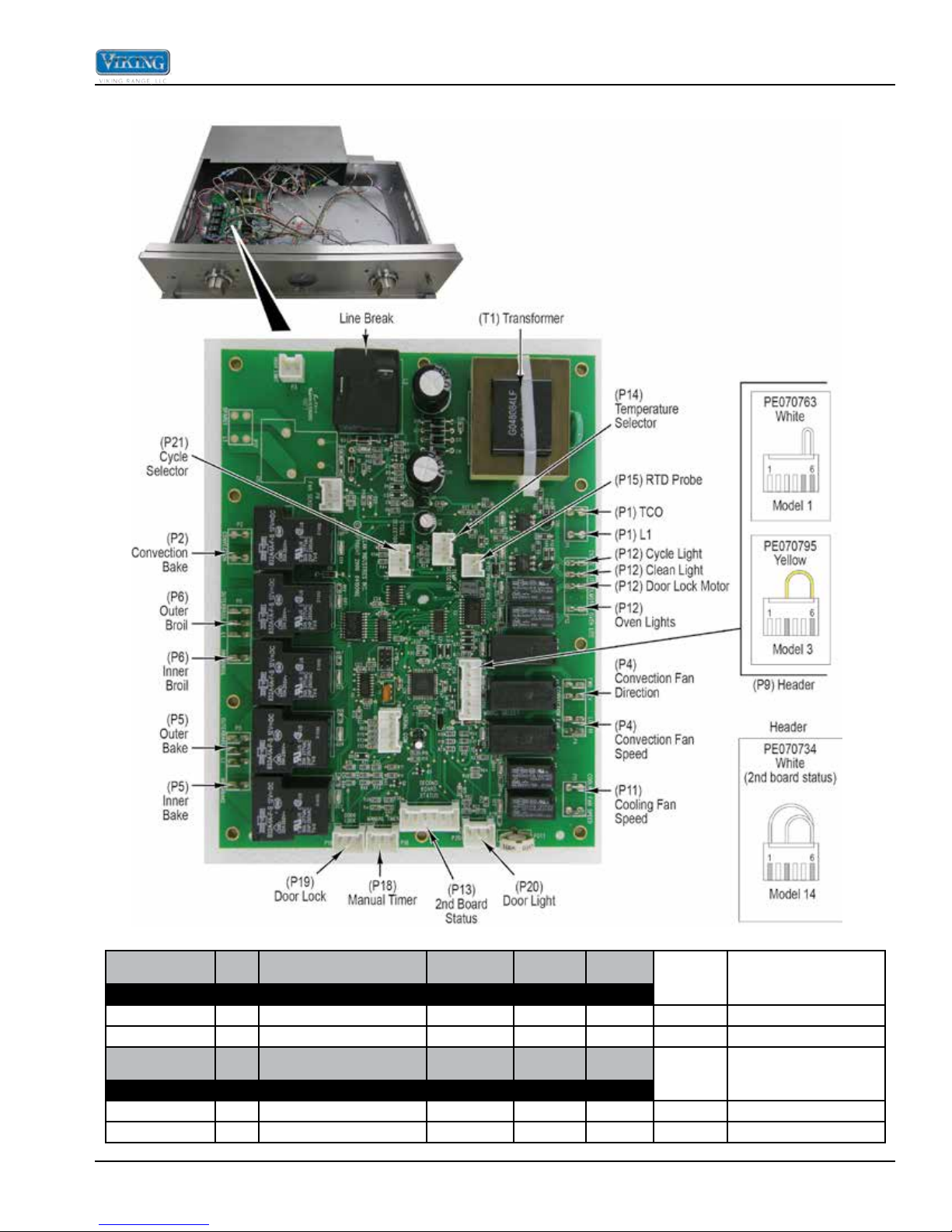
Parts Location – Control Board
Troubleshooting
Model Serial Description
Single Oven Status Select
VESO 5271 5272 N/A Pro - Single - Premiere - 27" PE070734 N/A White Model 14 - Pins 1, 3 and 6
VESO 5301 5302 N/A Pro - Single - Premiere - 30" PE070734 N/A White Model 14 - Pins 1, 3 and 6
Model Serial Description
Double Oven Status Select
VEDO 5271 5272 N/A Pro - Double - Premiere - 27" PE070734 N/A PE070795 Yellow Model 3 - Pins 3 , 6
VEDO 5301 5302 N/A Pro - Double - Premiere - 30" PE070734 N/A PE070763 White Model 1 - Pins 5 , 6
©2013 Viking Preferred Service 13
P13 - Second
Board
P13 - Second
Board
P9 - Model
P9 - Model
Select
P9 Model
Select
Wire Color Connections
Wire Color Connections
Troubleshooting
Control Board Test Points
Component Testing
Component Operating Voltage
(approximate)
Convection Element 240 VAC 18.2 W K17 yellow – white
Outer Broil Element 240 VAC 34.1 W K17 yellow – P6 grey
Inner Broil Element 240 VAC 30.6 W K17 yellow – P6 purple
Outer Bake Element 240 VAC 38.5 W K17 yellow – P5 blue
Inner Bake Element 240 VAC 38.2 W K17 yellow – P5 orange
RTD (Resistive Thermal
Device)
Convection Motor 240 VAC 100 W
Blower Motor(s) 120 VAC
Door Latch Motor 240 VAC 12.86K W L2 – P12 white
Door Latch Switch –
door unlocked
Door Latch Switch –
door unlocked
Door Latch Switch –
door locked
Door Latch Switch –
door locked
Thermal Cut-Out –
open contacts
Thermal Cut-Out –
closed contacts
Cycle Light 240 VAC ∞ (Open) (neon light) L2 – P12 grey
Clean Light 240 VAC ∞ (Open) (neon light) L2 – P12 purple
Oven Light Switch – off
(door closed)
Oven Light Switch – on
(door closed)
Oven Door Switch –
(door closed)
Oven Door Switch –
(door opened)
Analog Timer 240 VAC 679 W (On Timer) L1 – L2 (N)
Digital Timer 240 VAC 1.2 W (On Timer) L1 – L2 (N)
Oven Timer Selector
Switch - Single & Upper
Oven
Oven Timer Selector
Switch - Lower Oven
Oven Timer Selector
Switch - Manual Oven
*Resistance checks made with power off.
14 ©2013 Viking Preferred Service
5 VDC
5 VDC ∞ (Open)
0 VDC 0 W (Closed) P19 green – blue
0 VDC 0 W (Closed)
5 VDC ∞ (Open)
240 VAC ∞ (Open)
0 VDC 0 W (Closed)
18.5 VDC ∞ (Open)
0 VDC 0 W
0 VDC 0 W P20 brown – purple
17.7 VDC ∞ (Open)
- 0 W
- 0 W
- ∞ (Open)
1100 W @ 75°F (See chart
for more options)
18.2 W single oven
9.6 W double ovens
Resistance
(approximate)
Test Location
P15 pin 1 – pin 2
L2 – P4 blue (CCW)
L2 – P4 grey (CW)
N – P11 white/black
P19 green – orange
(disconnected from board)
P19 green – orange
(disconnected from board)
P19 green – blue
(disconnected from board)
L2 – P1 black (lower oven)
L2 – P1 grey (upper oven)
L2 – P1 black (upper oven)
L2 – P1 grey (lower oven)
P20 brown – grey
(disconnected from board)
P20 brown – grey
(disconnected from board
for resistence check)
P20 brown – purple
(disconnected from board
for resistence check)
Orange - Grey
(On Selector Switch)
Orange - Green
(On Selector Switch)
Orange - Grey
Orange - Green
(On Selector Switch)
Troubleshooting
To avoid risk of electrical shock, personal injury, or death, disconnect electrical power source to unit, unless test
procedures require power to be connected. Discharge capacitor through a resistor before attempting to service.
Ensure all ground wires are connected before certifying unit as repaired and/or operational.
Control Board Diagnosis
With the control board assembly accessed (see page
42), the following components can be diagnosed without
removal of the components.
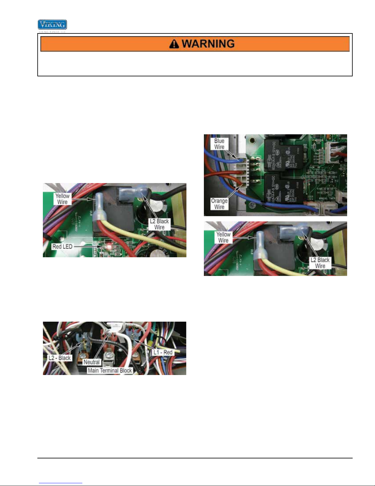
Line Break Relay
The line break relay breaks the L2-side of line voltage.
As the relay is energized, the relay closes and allows
L2 power to the convection, broil and bake elements.
Locate the line break relay on the control board. The
relay will have a black wire and a yellow wire connected
to it. The black wire is L2 input from the main power
supply. The yellow wire is L2 output from the line break
relay.
Bake Element
Locate the P5 connector and the line break relay on the
control board. The P5 connector will have a Molex plug
containing a blue, red, and orange wire. The blue wire
goes to the outer bake element, the orange wire goes to
the inner bake element, and the red wire is L1 input from
the main power supply.
When heating is selected by the control input, 12 VDC is
sent to the line break relay coil. A red LED in front of the
coil verifies coil voltage is being sent to the relay. This
does not indicate however that the relay is functioning.
To check the relay contacts, verify input voltage to the
relay between the black wire (L2) and red wire (L1) at
the main terminal block. You should read 240 VAC.
Select a cooking program. When the relay contact is
closed (red LED lit at base of relay) check for 240 VAC
between the yellow wire and red (L1). If 0 VAC is read,
disconnect power and remove the black and yellow wire
off the relay. Reconnect power and using your ohmeter
to check for continuity between the two relay contacts
when the relay is energized. If you read infinite ohms
(∞), this indicates a faulty relay and you will need to
replace the control board.
With the power off and the Molex connector removed
from the P5 control board connection, use an ohmeter
to measure resistance between the blue wire in the
Molex plug and the yellow wire from the line break
relay. This will measure the resistance of the outer
bake element and should be approximately 38 ohms.
Likewise, the inner bake element can be measured by
reading resistance between the orange wire in the Molex
plug and the yellow wire from the line break relay. A
resistance reading of approximately 38 ohms should be
found. If either element fails to read resistance, remove
element to repair or replace (Follow the bake element
disassembly procedure).
©2013 Viking Preferred Service 15
 Loading...