

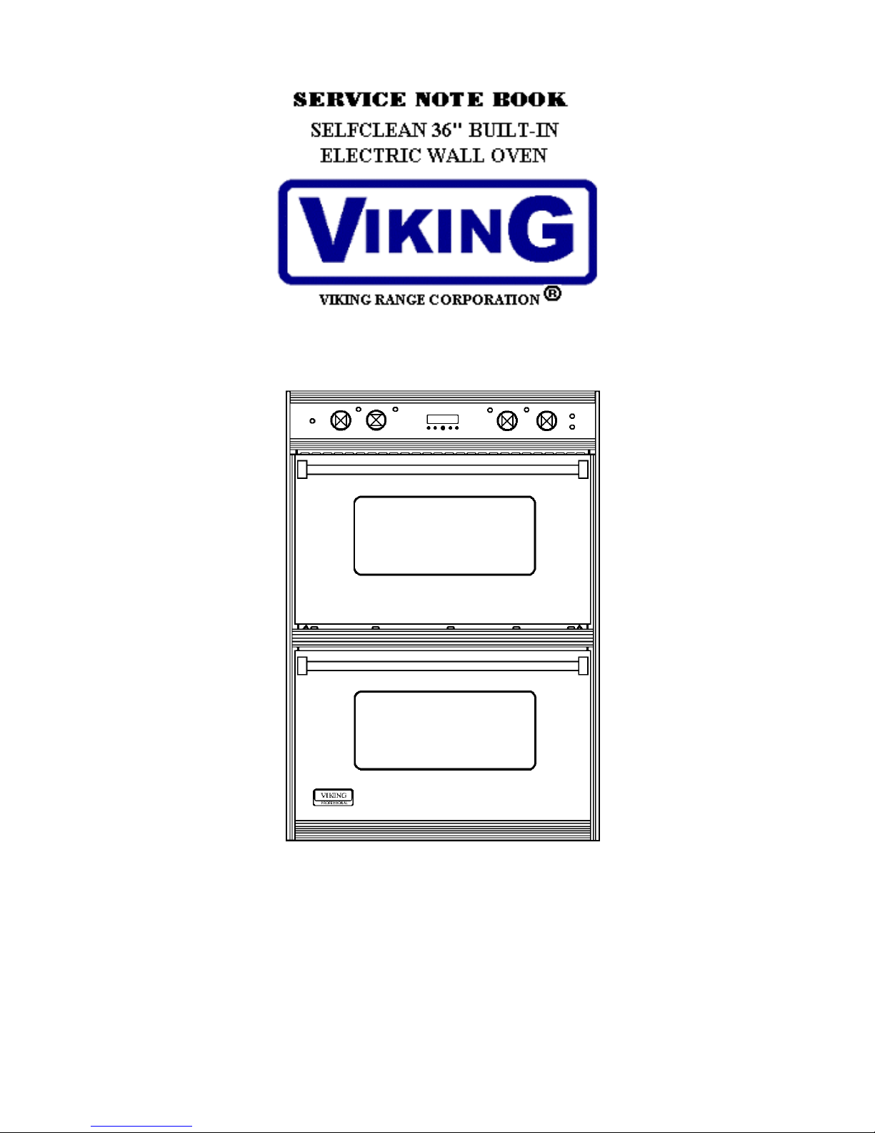
Viking veso165 Service Book
VIKING RANGE CORPORATION, P. O. DRAWER 956, GREENWOOD, MS.38930 USA
9/25/03 F90596
IMPORTANT INFORMATION
Pride and workmanship go into every product to provide our customers with quality products. It is
possible, however, that during its lifetime a product may require service. Products should be serviced
only by a qualified service technician who is familiar with the safety procedures required in the repair and
who is equipped with the proper tools, parts, testing instruments and the appropriate service manual.
REVIEW ALL SERVICE INFORMATION IN THE APPROPRIATE SERVICE MANUAL and
TECHNICAL SHEETS BEFORE BEGINNING REPAIRS.
Important Notice for Consumers and Services
To avoid risk of serious injury or death, repairs should not be attempted by an unauthorized personnel,
dangerous conditions (such as exposure to electrical shock) may result.
VIKING will not be responsible for any injury or property damage from improper service
procedures. If performing service on your own product, assume responsibility for any personal
injury or property damage which may result.
To locate an authorized servicer, consult the dealer from whom you purchased this product. For
further assistance, call:
Viking Technical Service
Phone # 800-914-4799
Address your written correspondence to: Viking Preferred Service
111 Front Street
P. O. Drawer 956
Greenwood, MS. 38935-0956
Recognize Safety Symbols, Words, and Labels
Danger-Immediate hazards which WILL result in severe personal injury
or death.
Warning-Hazards or unsafe practices which COULD result in severe
personal injury or death.
CAUTION-Hazards or unsafe practices which COULD result in minor
personal injury or product or property damage.
3
IMPORTANT INFORMATION
The information contained in this manual is intended for use by a qualified
service technician who is familiar with the application of all safety procedures
required in the repair of any gas or electric appliance, and who is equipped with the proper tools and
testing instruments.
Repairs covered in this manual and made by unqualified persons can result in
hazards developing due to improper assembly or adjustment.
Inexperienced persons making such repairs subject themselves to the risk of
injury or electrical shock which can be serious or even fatal.
IMPORTANT NOTE TO CUSTOMER
If you perform service on your own Viking product, you must assume responsibility of personal injury or
property damage which may result.
Viking will not be responsible for injury or property damage arising from service performed by other than
Viking Factory Authorized Service Agencies.
In order to locate a Viking Factory Authorized Service Agency, please consult the dealer from whom you
purchased this product. You may also write to:
Viking Preferred Service
P.O. Drawer 956
Greenwood, Ms. 38930
Important Safety Information
To avoid personal injury, do not sit or stand or lean on oven door.
To avoid risk of electrical shock, personal injury, or death, make sure
your oven has been properly grounded and always disconnect it from
main power supply before any servicing.
This appliance contains or produces a chemical or chemicals which can
cause death or serious illness and which are known to the state of
California to cause cancer, birth defects or other reproductive harm.. To reduce the risk from
substances in the fuel or from fuel combustion make sure this appliance is installed, operated,
and maintained according to the instructions in this booklet.
4

TABLE OF CONTENTS
Important Information------------------------------------------------------------------------ 3-4
Built-in 36” Electric Oven Features--------------------------------------------------------- 6
Electronic Timing Center-------------------------------------------------------------------- 7
Common Baking Remedies----------------------------------------------------------------- 10
Viking Model and Serial Numbers--------------------------------------------------------- 11
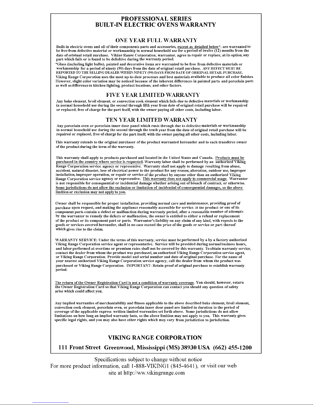
Warranty Statement-------------------------------------------------------------------------- 12
Electrical Requirements--------------------------------------------------------------------- 13
VESO165 Cutout Dimensions-------------------------------------------------------------- 14
VESO165 Oven Dimensions---------------------------------------------------------------- 15
VEDO265 Cutout Dimensions-------------------------------------------------------------- 16
VEDO265 Oven Dimensions--------------------------------------------------------------- 17
VESO/VEDO Component Access--------------------------------------------------------- 18
VESO/VEDO Component Layout--------------------------------------------------------- 19
VEDO Rear Component Layout----------------------------------------------------------- 20
Components-Color coded wiring---------------------------------------------------------- 21-23
Component Schematics--------------------------------------------------------------------- 24
Relay Diagrams------------------------------------------------------------------------------ 25
Clock/Timer—Meat Probe----------------------------------------------------------------- 26
VESO165 Pre-Heat Board------------------------------------------------------------------ 27
VEDO265 Pre-Heat Board (upper)-------------------------------------------------------- 28
VEDO265 Pre-Heat Board (lower)-------------------------------------------------------- 29
VESO165 8-Pos. Selector Switch--------------------------------------------------------- 30
VEDO265 8-Pos. Selector Switch. (upper)---------------------------------------------- 31
VEDO265 8-Pos. Selector Switch. (lower)---------------------------------------------- 32
VESO165 Wiring Diagram----------------------------------------------------------------- 33
Bake/Initial cycle with Preheat-------------------------------------------------------- 34
Bake After First Cycle------------------------------------------------------------------ 35
Convection Bake/Initial Cycle / Preheat---------------------------------------------- 36
Convection Bake After First Cycle---------------------------------------------------- 37
Convection Cook------------------------------------------------------------------------- 38
Broil---------------------------------------------------------------------------------------- 39
Maxi Broil--------------------------------------------------------------------------------- 40
Convection Broil------------------------------------------------------------------------- 41
Clean Initial Until Door Lock---------------------------------------------------------- 42
Door Lock After 575º F----------------------------------------------------------------- 43
Door Lock Below 575º F--------------------------------------------------------------- 44
Clean Finish------------------------------------------------------------------------------ 45
VEDO265 Wiring Diagram----------------------------------------------------------------- 46
Voltage and Resistance Reading----------------------------------------------------------- 47-48
8-Position Selection Switch----------------------------------------------------------------- 49
Oven Temperature Calibration------------------------------------------------------------- 50
Door Removal and Adjustment------------------------------------------------------------- 51
Lower Self-Clean Latch--------------------------------------------------------------------- 52
Troubleshooting Guide---------------------------------------------------------------------- 55-57
5

Built-in Electric Oven Features
6
Electronic Timing Center
The Electronic Timing Center is used to
program and control all timing functions. It has
five display and progra ng modes that are
activated by the four p sh buttons and the Set
mmi
u
Knob. Both the cook mode and the minute
timer mode can be used to time cooking periods.
These features can even be used at the same
when both ovens are in use. However only cook
time, probe, delay start and self-cleaning mode
shut the oven off automatically when the timed
program is over or internal temperature has been
reached. For example, you can time bake a
casserole in the upper oven using the cook time
mode, while broiling in the lower oven using the
minute timer. One oven can also be cleaned
while timing foods in the other using the minute
timer or cook time.
Setting the Time-of Day
The time-0f-day must be set before any other
timed programs can be used. When your oven
is first connected to the power in your home, the
timer display will show-- -- --along with the
“SET” icon and clock symbol icon. To set the
time-of-day.
. Press the CLOCK/PROBE button until
1
display shows the “SE
T” and clock symbol
icons.
2. Turn the SET knob until the correct time-of-
day is displayed, AM and PM are not
indicated.
3. Press the CLOCK/PROBE button again. If
the CLOC
K/PROBE button is not pressed
again, the new setting will automatically be
accepted after a 30 second timeout.
The minute timer, cook time, and probe
functions may be used without the clock
g set. However, the delay start
bein
feature relates to the time-of-day and can
not be used without a valid time of day
entry.
Setting the Timer
The timer function can be selected at any
time by pressing the TIMER
button.
This enters the SET TIME mode and the
display indicators show “SET TIMER”.
The timer setting is in hours/minutes
only. One (1) minute is the minimum
enterable time.
o program the Timer
T
1. Press the TIMER button. The timer
will display :00 and the display
indicators show “SET TIMER”.
2. Turn the SET knob in minute
intervals until the desired duration
time is displayed.
3. Five second
s after setting the Set
knob, the timer will start counting
down.
The alarm will beep once when the timer
has
reached a remaining time of one (1)
min cle,
ute. At the end of the timer cy
the alarm will beep three (3) times again
afte
r 10 seconds
While the timer is displayed, the Set
kno
b can be turned at any time to change
the the timer. After a 5 second
time on
meout, the timer will self-start again at
ti
the new setting.
If the TIMER button is pressed while the
timer is counting down and is active in
the display, the tim
mer setting is turned to :00 the timer
ti
er will cancel or if the
will be canceled.
7

During the timer countdown, a transition from
hours/minutes to minutes/seconds will be
made when one (1) hour remains. During the
countdown, the colon will flash to indicate
seconds activity.
Setting the Bake Time Program
The bake time function controls the timing of
baked or roasted foods. This function can be
selected at any time by pressing the BAKE
TIME button until the appropriate oven (upper
or lower) is displayed. This enters the bake
time mode and the display indicates “Set Bake
Time”. The bake time setting is in
hours/minutes only. One (1) minutes is the
minimum enterable time. NOTE: if the meat
probe is inserted in the oven, the bake timer
function for that oven is inaccessible.
To set the Bake Timer
1. Set the Oven Function Selector to Bake,
Convection Bake, or TruConvec™
position depending upon the type of
baking desired.
2. Set the Temperature Control Knob to the
desired temperature.
3. Press the BAKE TIME button until the
appropriate oven (upper or lower) is
displayed and the display indicates “Set
Bake Time”.
4. Turn the SET knob until the desired
cooking time is displayed. Five (5)
seconds after setting the SET knob, the
timer will automatically start counting
down.
The alarm will beep once when the timer has
reached a remaining time is one (1) minute.
At the end of the timer cycle, the alarm will
beep three (3) times.
While the timer is displayed, the SET knob
can be turned at any time to change the time
on the timer. After a 5 second timeout, the
timer will self-start at the new setting.
To cancel the bake time mode before the timer
has expired, turn the SET knob to 00:00.
NOTE: To use the automatic bake time
function, the manual time knob must be
turned to either the timed (for single
ovens), upper timed, lower timed, or
upper/lower oven timed setting
depending on which ovens are to use the
timed function.
Setting the Probe Program
The probe function controls the timing
of cooking meats based on the internal
temperature of the meat.
To set the Meat Probe
1. First insert the probe into the jack
located inside the oven.
2. Set the Oven Function Selector to
Bake, Convection Bake, or
TruConvec™ position depending
upon type of baking desired.
3. Turn the MANUAL/TIMED knob to
TIMED (for single ovens), UPPER
TIMED, LOWERED TIME, or
UPPER/LOWER TIMED function
depending on which ovens are being
used.
4. Set the Temperature Control Knob to
the desired temperature.
5. Press the CLOCK/PROBE button
until the appropriate oven display
(upper or lower) appears and the
display indicates “Probe”. NOTE:
When using a probe in both ovens,
you must set one oven at a time.
After setting the first oven, repeat
steps 5 and 6 for the second oven.
6. Turn the SET KNOB until the
desired internal temperature of the
meat is reached. NOTE: It is
recommended to set the temperature
5 to 10 degrees lower than desired
temperature. The meat will continue
to cook after being removed from the
oven.
7. This function will automatically start
five (5) seconds from the last input.
8

The oven will automatically shut off when the
set internal temperature is reached. The alarm
will beep once when the timer has reached a
remaining time of one (1) minute. At the end
of the timer cycle, the alarm will beep three
(3) times. If the Timer button is not pressed,
the alarm will beep three (3) times again after
10 seconds.
A delay start can also be used in conjunction
with this feature. To enter a delay start time,
press the DELAY START button after setting
the Temperature Control Knob and before
pressing the COOK/PROBE button. Turn the
SET knob until the desired start time is
reached. Then proceed with above steps
beginning with #5.
NOTE: To use the probe function, the manual
time knob must be turned to either the timed
(for single ovens), upper timed, lower timed,
or upper/lower oven timed setting depending
on which ovens are to use the timed function.
Setting the Automatic Delay Start/Bake
Time Program
The Bake Time and Delay Start modes of the
Timer can be used to automatically turn the
oven on and off at a pre-selected time. The
Automatic Bake Time Program is ideal for
foods with no danger of spoilage during the
time the oven is left off.
To set the Automatic Delay Start/Bake
Time Program
1. Turn the MANUAL/TIMED knob to
TIMED, UPPER OR LOWER TIMED
position, depending upon the oven mode
and oven being used.
2. Set the Oven Function Selector to the
BAKE, CONVECTION BAKE, or
TruConvec™ COOK position, depending
upon the type of baking being used.
3. Program the delay start by pressing the
DELAY START button and turning the
SET knob until the desired start time is
displayed. This is the time-of-day you
want the food to begin cooking.
4. Program the required cooking time by
pressing the BAKE TIME button. The
words “Set Bake Time” will appear in the
display. Turn the SET knob until the
desired cooking time is displayed in hours
and minutes. If a cook time or probe
temperature is not entered, the alarm will
beep every five seconds until a time or
temperature is entered.
5. Set the temperature Control Knob to the
desired temperature.
The oven will automatically start when the
start time of day is reached and will shut off
when the cook time or internal temperature is
reached. The alarm will beep once when the
timer has reached a remaining time of one (1)
minute. At the end of the time cycle, the
alarm will beep three (3) times. If the Timer
button is not pressed, the alarm will beep three
(3) times again after 10 seconds.
To avoid sickness or
the risk of food
poisoning and food waste when using
automatic time baking:
1) Do Not use foods that will spoil while
waiting for cooking to start, such as
dishes with milk or eggs, cream soups,
custards, fish, pork, poultry, or foods
with stuffing.
2) Any food that has to wait for cooking
to start should be very cold or frozen
before it is placed in the oven.
3) Do not use food containing baking
powder or yeast when automatic time
baking. They will not rise properly.
4) Do not allow food to remain in the
oven for more than two hours after the
end of the cooking cycle.
To avoid risk of
fire, do not line
the broiler grid with foil. **Foil may trap
grease on top of grid, close to heating
element causing a fire. ** Never leave
oven unattended while broiling.
Overcooking may result in a fire.
9

COMMON BAKING PROBLEMS / REMEDIES
PROBLEM CAUSE REMEDY
Cakes crack on top 1. Oven was too hot 1. Reduce temperature
or not done in center 2. Wrong pan size 2. Use recommended
pan size.
3. Too many pans 3. Reduce no. of pans.
Cakes crack on top 1. Batter too thick 1. Follow recipe add
L\liquid.
2. Oven too hot 2. Reduce temperature
3. Wrong pan size 3. Use proper pan size
Cakes are not level 1. Batter uneven 1. Distribute batter even
2. Oven or rack not level 2. Level oven or rack
3. Pan was warped 3. Use proper pan
Food too brown on 1. Oven door opened 1. Use door window to
Bottom too often check food.
2. Dark pans being used 2. Use shiny pans.
3. Incorrect rack position 3. Use recommended
rack position.
4. Wrong bake setting. 4. Adjust to conventional
or convection setting
as needed.
5. Pan too large 5. Use proper pan.
Food too brown on top 1. Rack position too high 1. Use recommended
rack position.
2. Oven not preheated 2. Allow oven to preheat
3. Sides of pan too high 3. Use proper pan.
Cookies too flat 1. Hot cookie sheet. 1. Allow sheet to cool
Between batches.
Pies burn around edges 1. Oven too hot. 1. Reduce temperature
2. Too many pans used. 2. Reduce no. of pans.
3. Oven not preheated. 3. Allow oven to preheat.
Pies too light on top 1. Oven not hot enough. 1. Increase temperature.
2. Too many pans used. 2. Reduce no. of pans.
3. Oven not preheated 3. Allow oven to preheat.
10
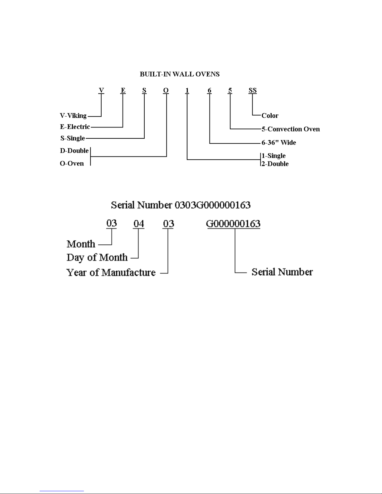
NEW VIKING MODEL NUMBERS
11
12
ELECTRICAL REQUIREMENTS
Description 36" Wide Single Oven 36" Wide Double Oven
Electrical Requirements 4-wire with ground, 240-208/120 VAC/60 Hz, 40 amp electrical
connection. Unit is equipped with No. 10 ground wire in conduit.
Should be fused separately.
Maximum Amp Usage 240V – 27.4 amps 240V - 54.8 amps
208V – 23.9 amps 208V – 47.8 amps
Pre-Heat Rating 240V –5750 Watts 240V – 11,500 Watts
208V –4319 Watts 208V – 8638 Watts
Broil Rating 240V 240V
Maxi Broil 8 pass 3000 watts 3000 watts
Mini Broil 4 pass 1250 watts 1250 watts
208V 208V
2250 2250
Bake Rating 240V - 3250 watts 240V - 3250 watts
208V – 2440 208V – 2440
Convection Cook Rating 240V - 2200 watts 240V - 2200 watts
208V – 1650 watts 208V – 1650 watts
940 940
ELECTRICAL CONNECTIONS
1. With the oven positioned in front of the cabinet opening, connect the wire leads
extending from the conduit to the junction box, making sure the neutral (white)
wire is connected to the appropriate terminal Check your local code to see
which of the following options below should be used in grounding the unit.
OPTION 1: Connect the neutral (white) wire and the grounding (green) wire with
the incoming neutral (white) power supply line.
OPTION 2: If the junction box is grounded, untwist the grounding (green) wire
and attach to the junction box. Attach the neutral (white) wire to the
neutral (white) power supply line.
OPTION 3: Untwist the grounding (green) wire and attach it to a suitable ground.
Attach neutral (white) wire to the incoming neutral (white) power
supply line.
DO NOT USE AN EXTENSION CORD WITH THIS
APPLIANCE. SUCH USE MAY RESULT IN A FIRE,
ELECTRICAL SHOCK OR OTHER PERSONAL INJURY.
13
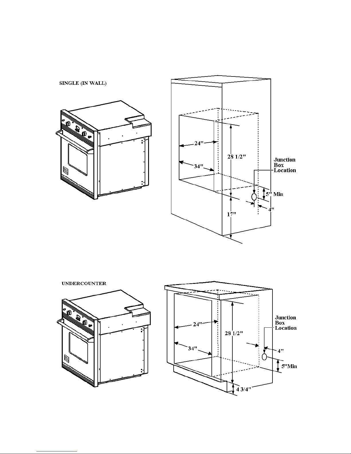
SINGLE OVEN CUTOUT DIMENSIONNS
14
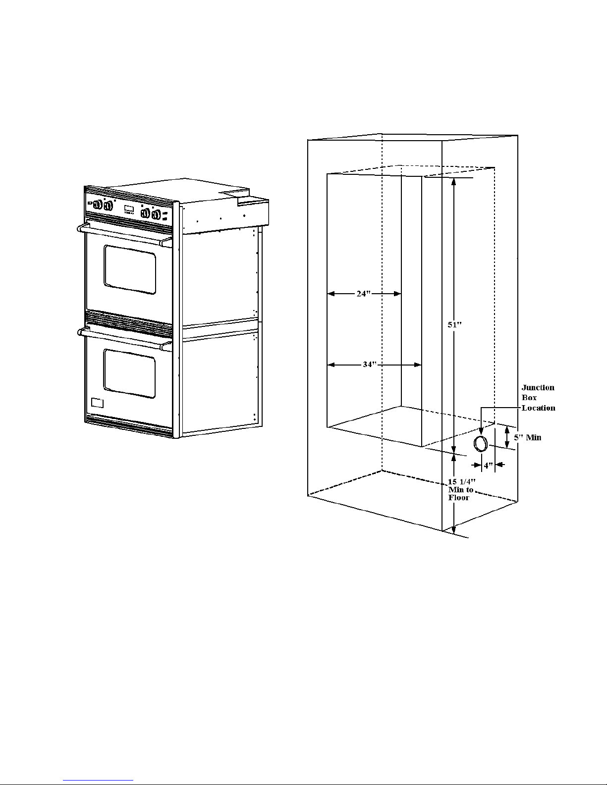
DOUBLE OVEN CUTOUT DIMENSIONS
15
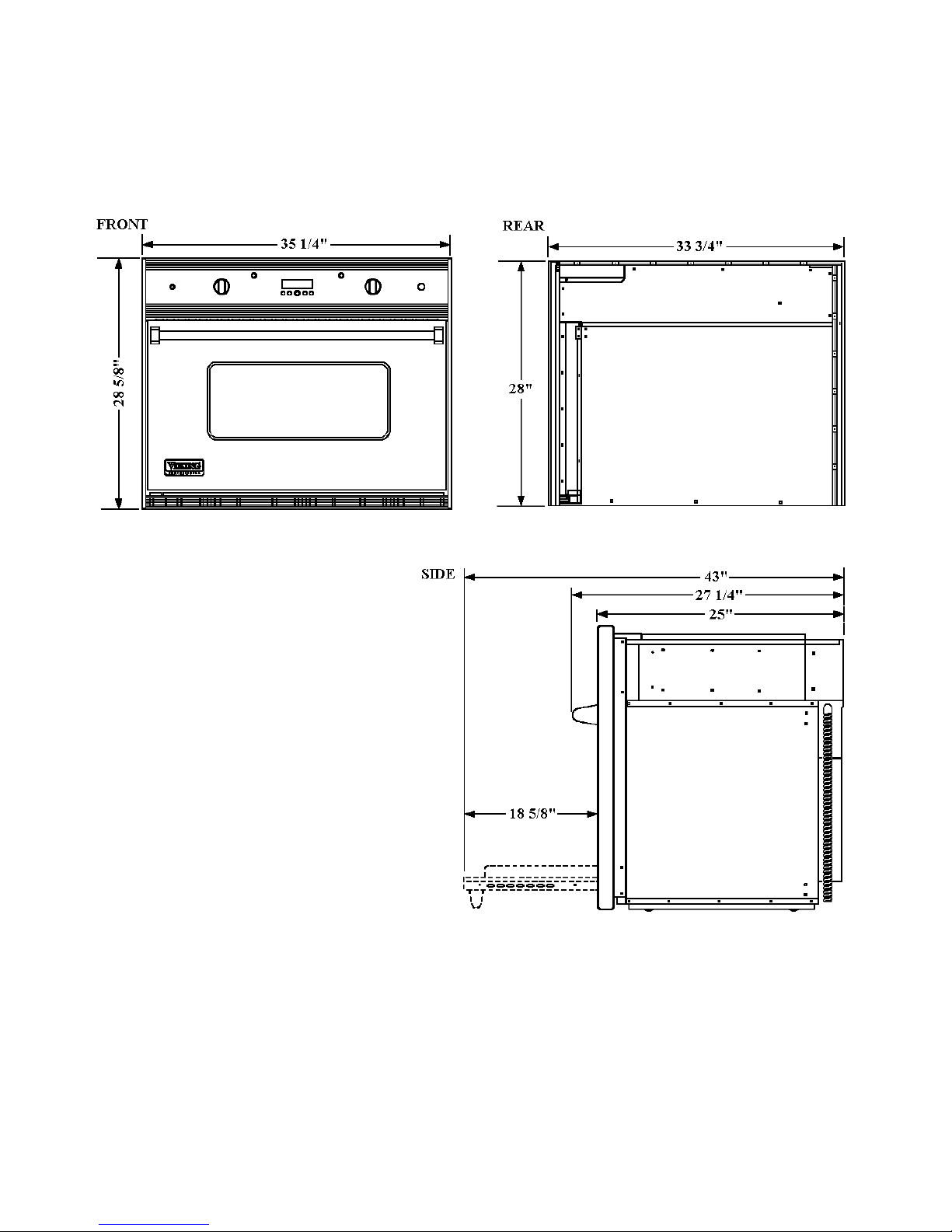
SINGLE OVEN DIMENSIONS
16
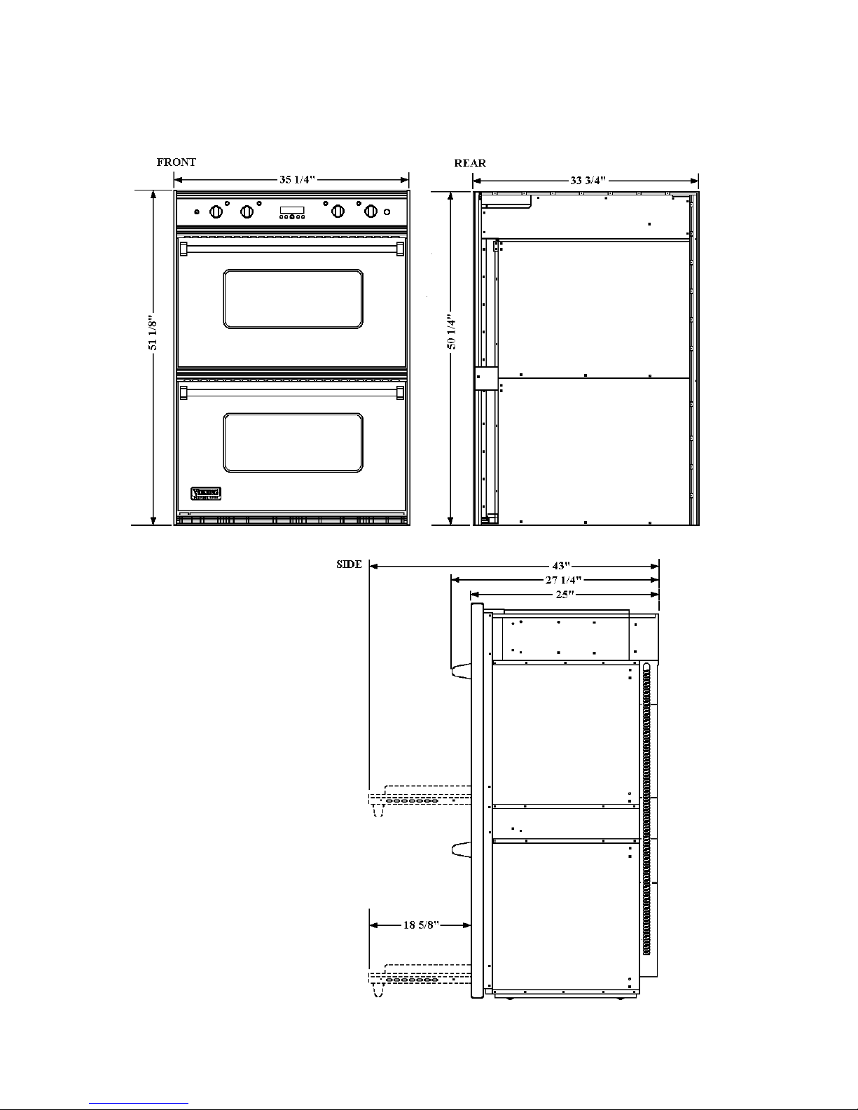
DOUBLE OVEN DIMENSIONS
17
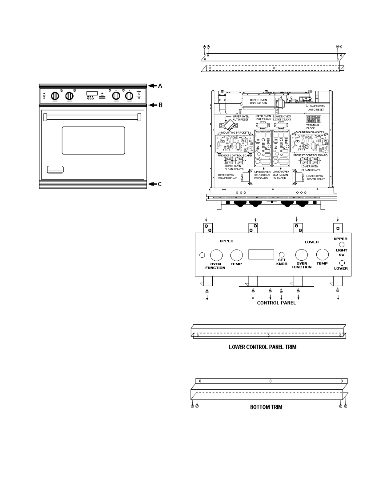
ILLUSTRATION # 1
VESO/VEDO COMPONENT ACCESS
To gain access to the electric and
electronic components:
Remove the top trim (A). Two screws at each
corner attaching the top trim to the side trims and
three screws along the bottom of the trim piece.
Remove the lower control panel trim (B).
Three screws along the bottom of the trim piece
behind the oven door.
Remove the control panel. Four screw at the
top and six screws across the bottom (see
drawing of the control panel). Pull the control
panel carefully forward and tilt down. Being
careful not to disconnect wires attached to the
components on the reverse of the panel.
The component panel is now accessible. Pull
the component panel forward to release the
panel from the slide.
Lift the component panel up to service the
upper oven self cleaning latch and components
located on the latch mechanism.
The bottom trim piece (C) is removed to make
the vertical door adjustment. Remove the two
screws from each corner attaching the bottom
trim to the side trim pieces. Remove the three
screws across the top of the trim piece located
beneath the door.
Top Trim
18
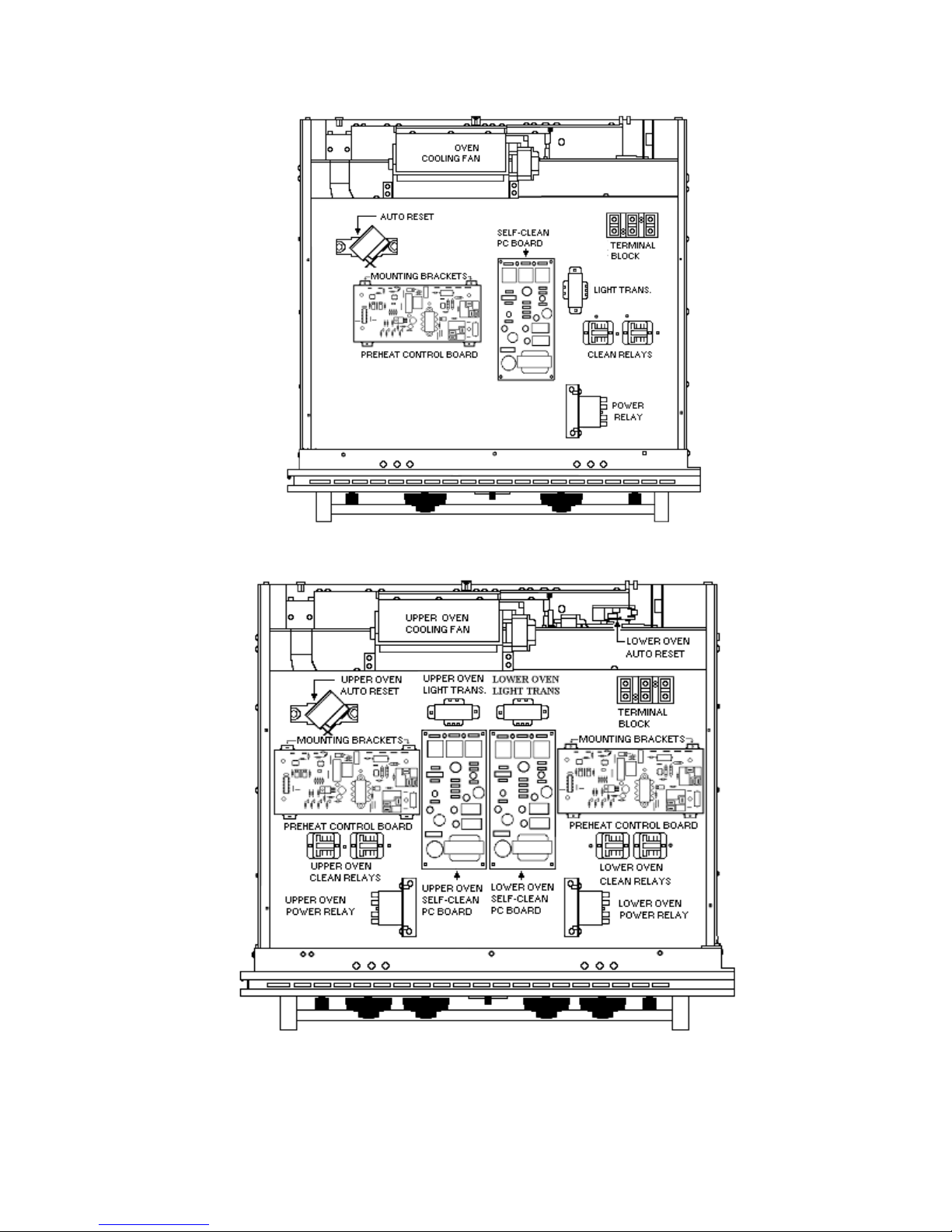
COMPONENT LAYOUT
VESO165
VEDO265
19
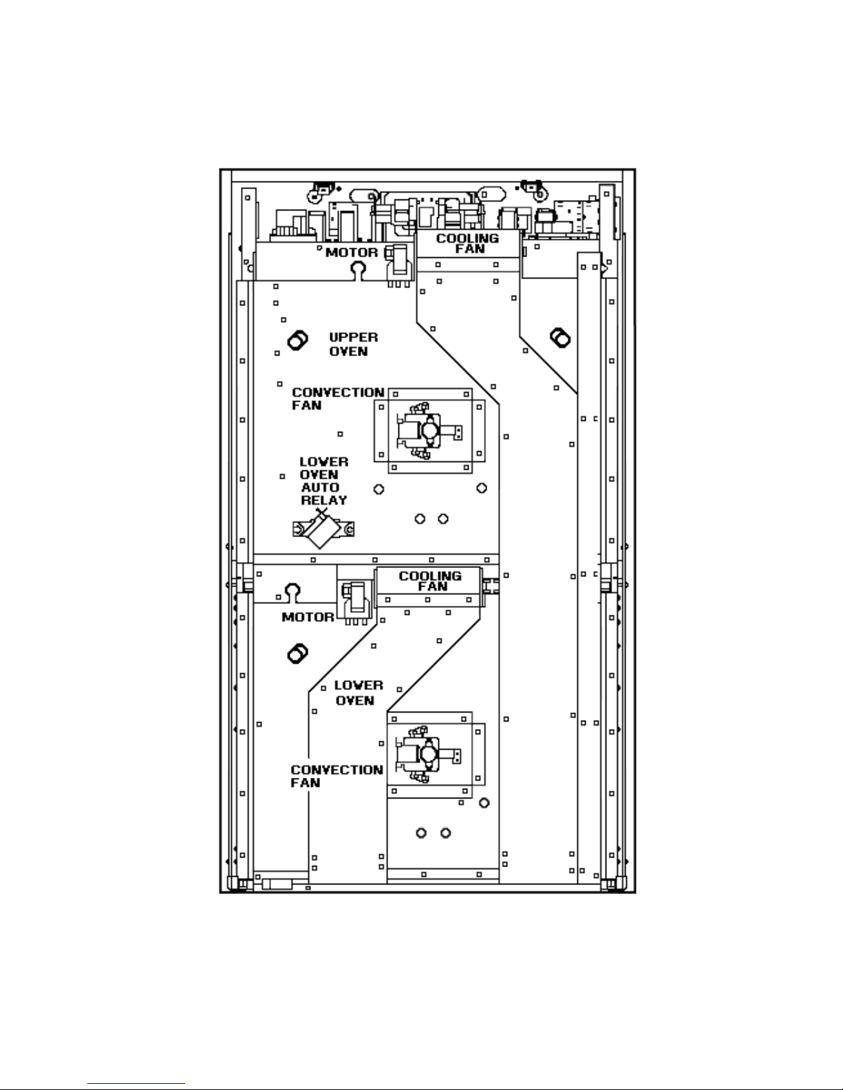
COMPONENT LOCATION VEDO265
(Rear View)
20
COMPONENTS
(With Color Coded Wires)
Door Lock Control / Timer
VESO165 / VEDO265
Function: The Door Lock
Control / Timer is
activated by the line voltage at
the “ SEL”
( 1 ) contact. Relay “ RL1" ( 2
) and “RL2"
( 3 ) close providing voltage to
the Door Lock Motor. The
Relays stay closed until 10
seconds after sensor #3 ( 4 )
receives a signal that the Door
Lock is fully closed. Once this
happens Relay “RL2" ( 3 )
opens to stop the Door Lock
Motor. Relay “RL1" ( 1 ) stays
closed providing voltage to the
Auto Reset thermostat. Relays
“RL3" and “RL4" close
powering the Cooling Fan
Motor and Cycle Relay.
“RL3" and “RL4" will stay
closed for 3 ½ hours unless
power is interrupted to sensor
#3 ( 4 ) or SEL ( 1 ). In which
case “RL3" and “RL4" will
open, interrupting the clean
cycle and Cooling Fan, and
“RL2" ( 3 ) will close, opening
the Door Lock. “RL2" ( 3) will
stay closed until 2 seconds
after sensor
# 4 ( 5 ) is powered.
21
 Loading...