

Viking 30'' W, VDSC305, VDSC365, VDSC485RHVDSC485LH, VESC305 Service Notebook
...
VIKING RANGE CORPORATION, P. O. DRAWER 956, GREENWOOD, MS.38930 USA

TABLE OF CONTENTS
VDSC / DUAL FUEL SELF-CLEAN RANGE
VESO SINGLE ELECTRIC SELF-CLEAN WALL OVEN
VEDO DOUBLE ELECTRIC SELF-CLEAN WALL OVEN
COMPONENTS AND FUNCTIONAL PARTS:
Viking Model Numbers..............................................................................................................………. 4
Serial Number Logic..................................................................................................… 6
Product Warranty................................................................................................................................... 7
Cabinet Clearances...............................................................................................................................… 9
Built-in Electric 30" Wall Ovens..........................................................................................….............. 10
Electrical Requirements.......................................................................................................................... 10
Cabinet Cutout Dimensions.................................................................................................................... 11
Components.............................................................................................................................................. 14
Control Circuit Board Voltage Checks.................................................................................................. 19
Bake/Broil
8-PositionSelector Switch........................................................................................................................ 22
/ Convection Element Checks....................................................................... 21
Oven Calibration........................................................................................................… 23
Power Relay....................................................................................................................... 24
Wiring Diagrams................................................................................................................ 25
Built-in Electric 30" Wall Oven.................................................................................... 25
Bake.................................................................................................................... 27
Convection Bake.......................................................................................…......... 28
Convection Cook........................................................................................................................ 29
Mini -Broil.................................................................................................................................. 30
Maxi Broil................................................................................................................................... 31
Convection Broil........................................................................................................................ 32
Clean Initiate Until Door Lock.............................................................................................… 33
Clean Door Lock Below 575* +/- 25*....................................................................................... 34
Clean Door Lock Above 575* +/- 25*....................................................................................... 35
Clean Finished Door Lock Above 525* +/-25*........................................................................ 36
Clean Finished Door Lock Below 525* +/-25*........................................................................ 37
Door Removal VESO / VEDO................................................................................................................ 38
Electrical Connections--Dual Fuel......................................................................................................... 42
Disassembly.............................................................................................................................................. 44
“Locked” Door............................................................................................................................………. 47
VERT / VESC.......................................................................................................................................... 48
Heating Elements (Resistance and Voltage Readings)........................................….............................. 49
2

IMPORTANT INFORMATION
The information contained in this manual is intended for use by a qualified service technician who is
familiar with the application of all safety procedures requ i red in the repair of any gas or electric appliance,
and who is equipped with the proper tools and testing instruments.
Repairs covered in this manual and made by unqualified persons can result in hazards developing due to
improper assembly or adjustment.
Inexperienced persons making such repairs subj ect themselves to the risk of injury or electrical shock
which can be serious or even fatal.
IMPORTANT NOTE TO CUSTOMER
If you perform service on your own Viking product, you must assume respon sibility of personal injury or
property damage which may result.
Viking will not be responsible for injury or property damage arising from service performed by other than
Viking Factory Authorized Service Agen cies.
In order to locate a Viking Factory Authorized Service Agency, please consult the dealer from whom you
purchased this pr oduct. You may also write to:
Viking Preferred Service
P.O. Drawer 956
Greenwood, Ms. 38930
3
NEW VIKING MODEL NUMBERS
RANGES AND RANGETOPS
V G R C 4 8 5 4 G Q D S S
V-Viking Color
AL-Almond
G-Gas Bk-Black
BU-Burgundy
SS-24" D EW-Euro White
Standard Range (30"W) FG-Forest Green
SC-27" D PL-Plum
Convection Range (30"W) SS-Stainless Steel
VB-Viking Blue
RC-27" D WH-White
Convection Range (36"/48"W)
RT-24" D
Rangetop
Width
30"
36"
48" D-Oven Door Window
60"
Q-12" Wide Grill
0-Standard Oven
5-Convection Oven G-Griddle
12" Wide
24" Wide
Number of Surface Burners
4
VIKING RANGE MODEL NUMBERS
BUILT-IN OVENS
V G D O - 2 7 0 - S S
V-Viking Color
Al - Almond
G-Gas BK - Black
E-Electric BU - Burgundy
FG - Forest Green
DO-Double Oven PL - Plum
SO-Single Oven SS - Stainless Steel
TE - Teal
Number of Oven Cavities VB - Viking Blue
1 - Single Oven WH - White
2 - Double Oven
Type
0 - Standard Bake
and Broil
5 - Convection
Width
6 - 36" Wide
7 - 27" Wide
5
VIKING SERIAL NUMBER LOGIC
RANGES and WALL OVENS
V 06 12 98 1 2 3 4 5 6
R - Range Production Control
T - Rangetop
B - Built-in ovens Calendar Year
Month of the Year Day of the Month
27" Wide Self-clean Ovens
94 06 012345
Calendar Year Production Control
Month of Year
6

VIKING RANGE CORPORATION
PRODUCT WARRANTY
COOKING PRODUCTS
FREE STANDING GAS RANGES
*
90 DAYS-GLASS, PAINTED, PORCELAIN AND
DECORATIVE ITEMS
* 1 YEAR FULL WARRANTY-COMPONENTS AND
ACCESSORIES
* 5 YEAR LIMITED WARRANTY-SURFACE BURNER,
GRIDDLE TUBULAR BURNER, GRILL TUBULAR
BURNER (PART ONLY)
• 10 YEAR LIMITED WARRANTY-ANY PORCELAIN
OVEN OR PORCELAIN INNER DOOR WHICH
RUSTS THROUGH
DUAL FUEL RANGES
* 90 DAYS-GLASS, PAINTED, PORCELAIN AND
DECORATIVE ITEMS
* 1 YEAR FULL WARRANTY-COMPONENTS AND
ACCESSORIES
* 5 YEAR LIMITED WARRANTY-SURFACE BURNER,
GRIDDLE TUBULAR BURNER, GRILL TUBULAR
BURNER, BAKE ELEMENT, BROIL ELEMENT, OR
CONVECTION COOK ELEMENT (PART ONLY)
* 10 YEAR LIMITED WARRANTY-ANY PORCELAIN
OVEN OR PORCELAIN INNER DOOR PANEL WHICH
RUSTS THROUGH
ELECTRIC RANGES
* 90 DAYS-GLASS, PAINTED, PORCELAIN AND
DECORATIVE ITEMS
* 1 YEAR FULL WARRANTY-COMPONENTS AND
ACCESSORIES
* 5 YEAR-ANY HALOGEN ELEMENT, BAKE
ELEMENT, BROIL ELEMENT, OR CONVECTION
COOK ELEMENT (PART ONLY)
* 10 YEAR LIMITED WARRANTY-ANY PORCEOAIN
OVEN OR PORCELAIN INNER DOOR PANEL WHICH
RUSTS THROUGH
GAS RANGETOPS
* 90 DAYS -GLASS, PAINTED, PORCELAIN AND
DECORATIVE ITEMS
* 1 YEAR FULL WARRANTY-COMPONENTS AND
ACCESSORIES
* 5 YEAR LIMITED WARRANTY-SURFACE BURNERS,
GRIDDLE TUBULAR BURNER, GRILL TUBULAR
BURNER (PART ONLY)
ELECTRIC RANGETOP
* 90 DAYS-GLASS, PAINTED, PORCELAIN AND
DECORATIVE ITEMS
* 1 YEAR FULL WARRANTY-COMPONENTS AND
ACCESSORIES
* 5 YEAR-ANY HALOGEN ELEMENT, BAKE
ELEMENT, BROIL ELEMENT, OR CONVECTION
COOK ELEMENT (PART ONLY)
GAS WALL OVENS
* 90 DAYS-GLASS, PAINTED, PORCELAIN AND
DECORATIVE ITEMS
* 1 YEAR FULL WARRANTY-COMPONENTS AND
ACCESSORIES
* 5 YEARS-OVEN TUBULAR BURNER (PART ONLY)
* 10 YEAR LIMITED WARRANTY-ANY PORCELAIN
OVEN OR PORCELAIN INNER DOOR PANEL WHICH
RUSTS THROUGH
ELECTRIC WALL OVENS
* 90 DAYS-GLASS, POINTED, PORCELAIN AND
DECORATIVE ITEMS
* 1 YEAR FULL WARRANTY-COMPONENTS AND
ACCESSORIES
* 5 YEARS LIMITED WARRANTY-OVEN BAKE,
BROIL, OR CONVECTION HEATING ELEMENTS
* 10 YEAR LIMITED WARRANTY-ANY PORCELAIN OR
PORCELAIN INNER DOOR PANEL WHICH RUSTS
THROUGH
WARMING DRAWERS
* 90 DAYS-PAINTED AND DECORATIVE ITEMS
* 1 YEAR FULL WARRANTY-COMPONENTS AND
ACCESSORIES
* 5 YEAR LIMITED WARRANTY-HEATING ELEMENT
VENTILATION PRODUCTS
* 90 DAYS-PAINTED AND DECORATIVE ITEMS
* 1 YEAR FULL WARRANTY-COMPONENTS AND
ACCESSORIES
* 2 YEAR LIMITED WARRANTY-BLOWER MOTOR
OR EXTERIOR VENTILATOR MOTOR
KITCHEN CLEAN-UP
DISHWASHER
* 90 DAYS-PAINTED OR DECORATIVE ITEMS
* 1 YEAR FULL WARRANTY-COMPONENTS AND
ACCESSORIES
* 5 YEAR LIMITED WARRANTY-MOTOR/PUMP AND
WATER DISTRIBUTION SYSTEM COMPONENTS
* CIRCULATION PUMP
* DRAIN MOTOR/PUMP
* FILL V ALVE
* LOWER WASH ARM
* TUBE TO UPPER WASH ARM
* UPPER WASH ARM
* 25 YEAR LIMITED WARRANTY-STAINLESS STEEL
TANK OR INNER DOOR LINER WHICH DEVELOPS A
WATER LEAK
TRASH COMPACTORS
* 90 DAYS-PAINTED OR DECORATIVE ITEMS
* 1 YEAR FULL WARRANTY-COMPONENTS AND
ACCESSORIES
* 5 YEAR LIMITED WARRANTY-DRIVE SYSTEM
MOTOR
DISPOSERS
* VCFW 1020 AND VBFW
* 7 YEAR FULL WARRANTY
* VCHW 1000 AND VBHW 1030
* 5 YEAR FULL WARRANTY
7

PRODUCT WARRANTY (CONTINUED)
REFRIGERATION PRODUCTS
REFRIGERATION
* 90 DAYS-PAINTED OR DECORATIVE ITEMS
* 2 YEARS FULL WARRANTY
* 6 YEARS FULL WARRANTY ON SEALED SYSTEM
COMPONENTS
* COMPRESSOR
* CONDENSER
* DRYER/STRAINER
* EVAPORATOR
* CONNECTING TUBING
* 12 YEAR LIMITED WARRANTY-SEALED SYSTEM
COMPONENT (PARTS ONLY)
* COMPRESSOR
* CONDENSER
* DRYER/STRAINER
* EVAPORATOR
* CONNECTING TUBING
ICE MAKER
* 90 DAYS-PAINTED OF DECORATIVE ITEMS\
* 2 YEAR FULL WARRANTY
* 6 YEAR FULL WARRANTY ON SEALED SYSTEM
COMPONENT
* COMPRESSOR
* CONDENSER
* DRYER/STRAINER
* EVAPORATOR
* CONNECTING TUBING
* 12 YEAR LIMITED WARRANTY-SEALED SYSTEM
COMPONENT (PART ONLY)
* COMPRESSOR
* CONDENSER
* DRYER/STRAINER
* EVAPORATOR
* CONNECTING TUBING
WINE COOLER
* 90 DAYS-PAINTED OR DECORATIVE ITEMS
* 2 YEAR FULL WARRANTY
* 6 YEAR FULL WARRANTYON SEALED SYSTEM
COMPONENT
* COMPRESSOR
* CONDENSER
* DRYER/STRAINER
* EVAPORATOR
* CONNECTING TUBING
* 12 YEAR LIMITED WARRANTY-SEALED SYSTEM
COMPONENT (PART ONLY)
* COMPRESSOR
* CONDENSER
* DRYER/STRAINER
* EVAPORATOR
* CONNECTING TUBING
OUTDOOR PRODUCTS
GAS GRILLS
ITEMS
* 90 DAY-PAINTED, PORCELAIN, AND DECORATIVE
* 1 YEAR FULL WARRANTY
* 5 YEAR LIMITED WARRANTY-CAST IRON BURNER
ASSEMBLIES, INFRARED ROTISSERIE BURNERS,
AND PORCELAIN GRILL GRATES
* LIFETIME WARRANTY-STAINLESS STEEL PART
WHICH RUST THROUGH
8
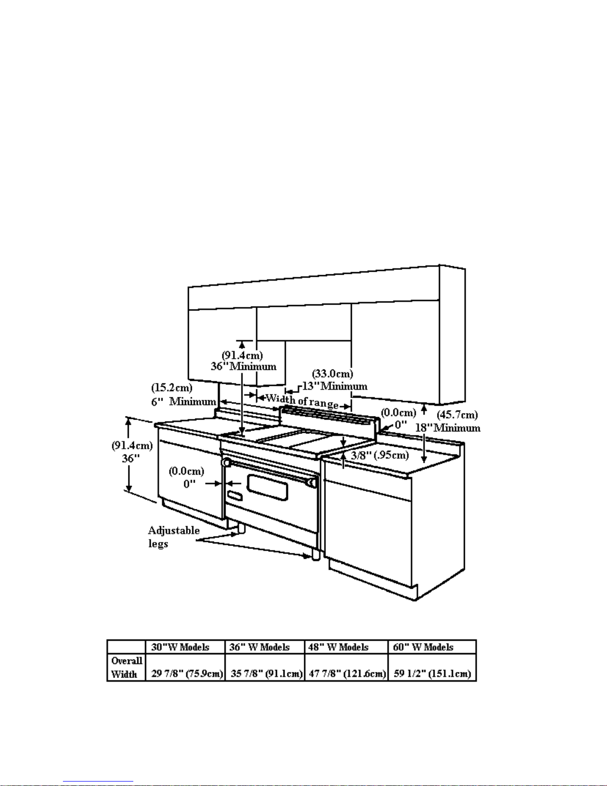
PROXIMITY TO SIDE CABINET INSTALLATIO N
1. Range / Range tops may be installed directly adjacent to existing 36" high base cabinets.
IMPORTANT-the top grate support MUST be 3/8" above the adjacent base cabinet countertop.
This may be accomplished by raising the unit, ( using the adjustment spindles on the range legs)
or ( using shims for the range top).
2. The ra nge / range top CANNOT be installed directly adjacent to sidewalls, tall cabinets, tall appli-
ances, or other side vertical surfaces above 36" high. There must be a minimum of 6" side clearance
from the range to such combustible surfaces above the 36" counter height.
3. Within the 6"side clearance to combustible vertical surfaces above 36", the maximum wall cabinet
depth must be 13" and wall cabinets within this 6"side clearance must be 18" above the 36" high
countertop.
4. Wall cabinets above the range / range top must be a minimum of 36" above the cooking surface for
the full width of the range / range top.
9
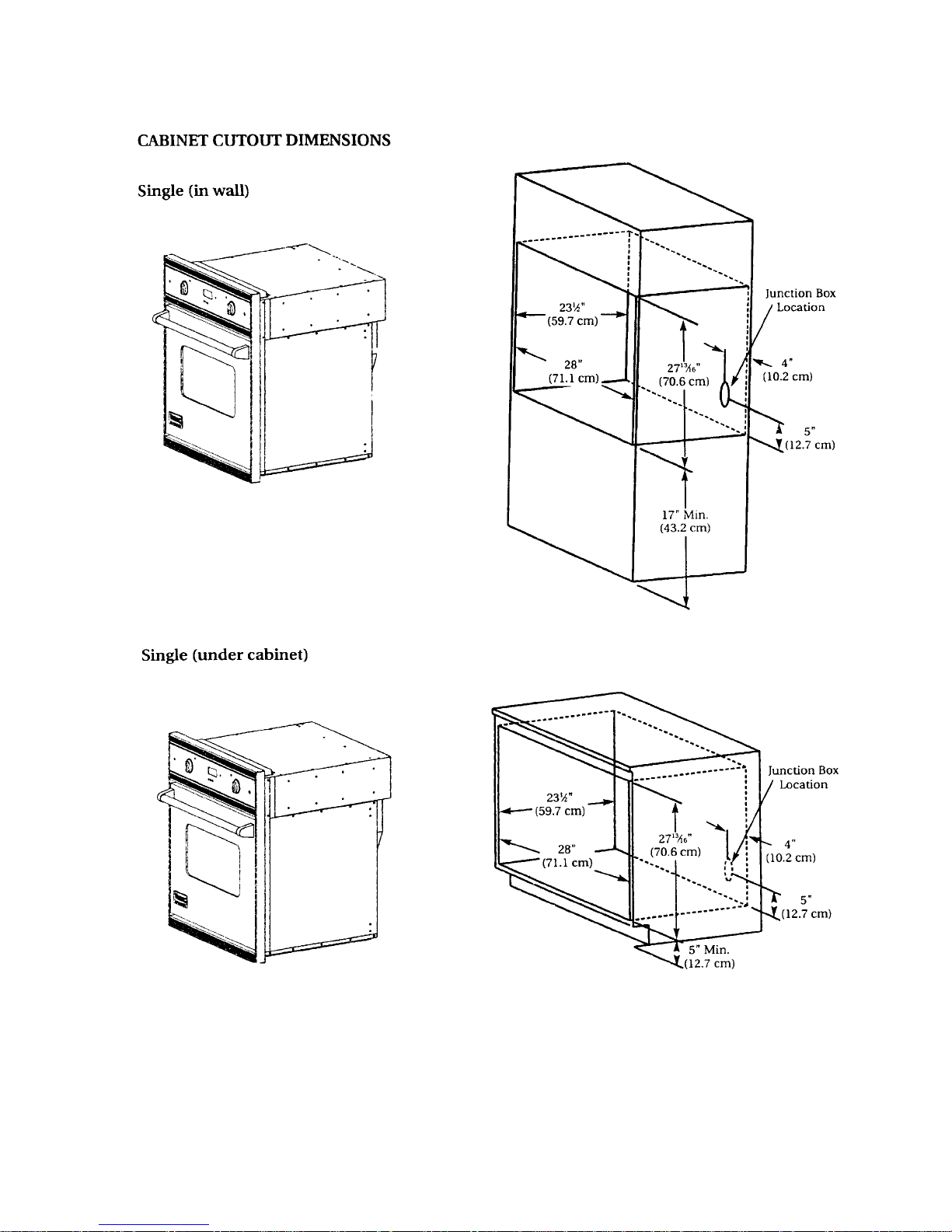
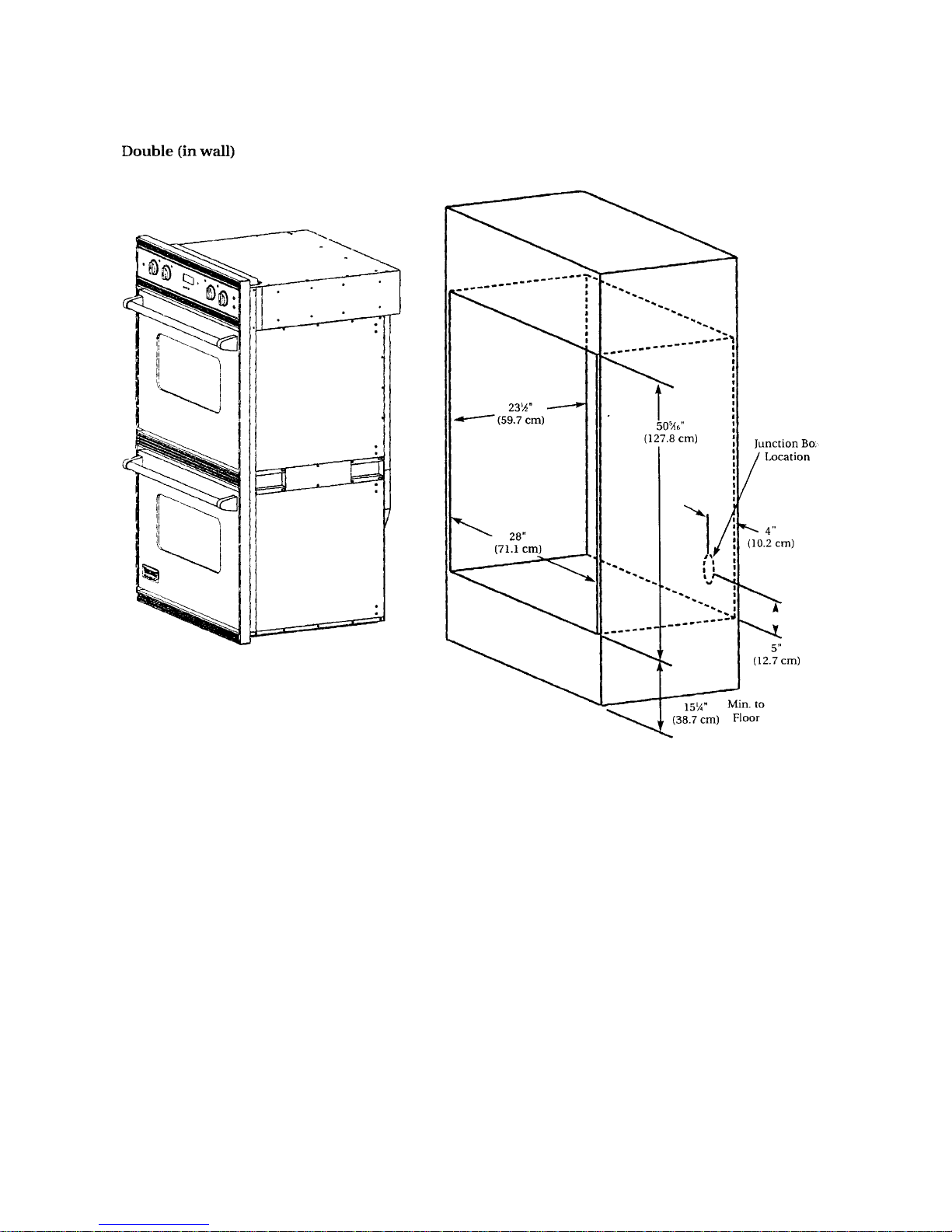
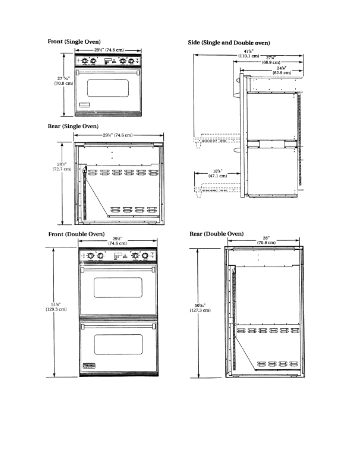
BUILT-IN ELECTRIC 30" WALL
ELECTRICAL REQUIREMENTS
Description 30" Wide Single Oven 30" Wide Double Oven
Electrical Requirements 4-wire with ground, 240-208/120 VAC/60 Hz, 40 amp electrical
connection. Unit is equipped with No. 10 ground wire in conduit.
Should be fused separately.
Maximum Amp Usage 240V - 18.9 amps 240V - 31.8 amps
208V - 14.2 amps 208V - 23.9 amps
Broil Rating 240V 208V
Maxi Broil 8 pass 3000 watts 2250 watts
Baking Rating 240V - 2935 watts 208V - 2205 watts
Convection Cook Rating 240V - 2200 watts 208V - 1650 watt
Mini Broil 4 pass 1250 watts 940 watts
ELECTRICAL CONNECTIONS
1. With the oven positioned in front of the cabinet opening, connect the wire leads extending from the
conduit to the junction box, making sure the neutral (white) wire is connected to the appropriate
terminal Check your local code to see wh ich of the following options below shou ld be used in
grounding the unit.
OPTION 1: Connect the neutral (white) wire and the grounding (green) wire with the incoming
neutral (white) power supply line.
OPTION 2: If the junction box is grounded, untwist the grounding (green) wire and attach to the
junction box. Att ach the neutral (white) w i r e to the neutral (white) po wer supply line.
OPTION 3: Untwist the grounding (green) wire and attach it to a suitable ground. Attach neutral
(white) wire to the incoming neutral (white) power supply line.
DO NOT USE AN EXTENSION CORD WITH THIS APPLIANCE. SUCH USE MAY RESULT IN A FIRE,
ELECTRICAL SHOCK OR OTHER PERSONAL INJURY.
10
11
12
13
COMPONENTS
(WITH COLOR CODED WIRES)
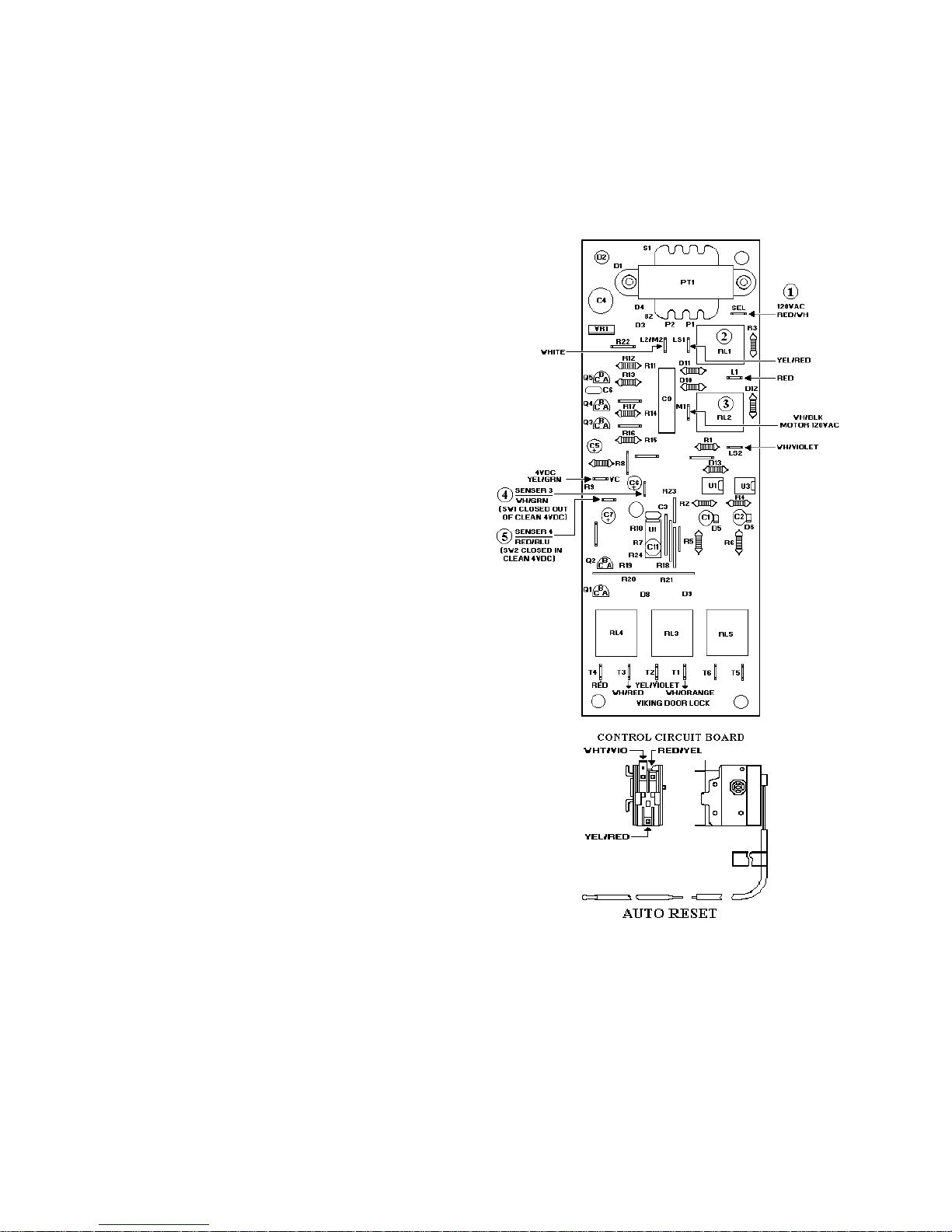
DOOR LOCK CONTROL / TIMER
VDSC305-VDSC365VDSC485(RH)
VDSC485(LH)-VESC305VESO105 VEDO205
Function: The Door Lock Control / Timer is
activated by the line voltage at the “ SEL”
( 1 ) contact. Relay “ RL1" ( 2 ) and “RL2"
( 3 ) close providing voltage to the D oor Lock
Motor. The Relays stay closed until 10
seconds after sensor #3 ( 4 ) receives a signal
that the Door Lock is fully closed. Once this
happens Relay “RL2" ( 3 ) opens to stop the
Door Lock Motor. Relay “RL1" ( 1 ) stays
closed providing voltage to the Auto Reset
thermostat. Relays “RL3" and “RL4" close
powering the Cooling Fan Motor and Cycle
Relay. “RL3" and “RL4" will stay closed for
3 ½ hours unless power is interrupted to
sensor #3 ( 4 ) or SEL ( 1 ). In which case
“RL3" and “RL4" will open, interrupting the
clean cycle and Cooling Fan, and “RL2" ( 3 )
will close, opening the Door Lock. “RL 2" ( 3)
will stay closed until 2 seconds after sensor
# 4 ( 5 ) is powered.
AUTO RESET SWITCH
VDSC305-VDSC365-VDSC485(RH)VDSC485(LH)-VESC305-VESO105-VEDO205
Function: The Auto Reset Switch is a single
pole / double throw switch ( thermostat )
which is activated by a therm o- bulb an d lev er
which is cal ibrated to 575* F plus / m inus 25*
F. Clean door lock below 575* F. The Door
Lock Motor is energized through the Auto
Reset Switch ( thermostat ) contacts 2 - 1.
Clean door lock above 575* F. Auto Reset
Switch (thermostat ) switches to contacts 1 -3
turning on the Door Lock i n di cator L i g h t an d
disables the Door Lock Motor circuit. Final
below 575* F. Auto Reset Switch (
thermostat ) switches to contacts 1 -2, turning
off the Door Lock Motor circuit through door
Lock Motor / Timer Relay LS2 - M1. Door
Lock Motor operates until 2 seconds after
sensor 4 is sig naled by VC that the Do or L ock
switch SW1 has been closed m echanically by
the door lock bolt. The Door Lock / Timer
switches LS2 - M1 and LS1-L1 open and the timer
14

COMPONENTS ( Con’t )
HIGH LIMIT SWITCH
VDSC305-VDSC365-VDSC485(RH)
VDSC485(LH)-VESC305-VESO105-VEDO205
Function: The Switch has a ½ “ bi-metal
disc. The two metals have different thermal
coefficients of expans ion which cau se the di sc
to bow as it heats up. When it reaches the
calibration temperature the disc snaps open,
which opens the electrical contacts. The
Switch opens w hen tem perature reaches 275*
F plus or minus 9*F and will close when
temperatures are 248* F plus or minus 9*F.
COOLING FAN LIMIT SWITCH
VDSC305-VDSC365-VDSC485(RH)VDSC485(LH)-VESC305-VESO105-VEDO205
Function: The Switch has a ½ “ bi-metal disc.
The two metals have different thermal
coefficients of expans ion which cau se the di sc
to bow as it heats up. When it reaches the
calibration temperature the disc snaps clos ed,
which closes the electrical contacts. The
Switch closes when temperatures reach 230* F
plus or minus 9* F and will open when
temperatures are below 203* F plus or minus
9*F.
SELECTOR SWITCH (8 POS) (PJ030001)
VDSC305-VDSC365-VDSC485(RH)-VESC305VESO105-VEDO205
Function: Rotating the shaft twists a cam
which moves one or more spring loaded
levers, which make contact with a terminal
closing the circuit.
SELECTOR SWITCH (PJ030009)
VDSC485(LH)
SELECTOR SWITCH (3 POS) (PJ030010)
VESO105-VEDO205
OVEN THERMOSTAT
VDSC305-VDSC365-VDSC485(RH)VDSC485(LH)-VESC305-VESO105-VEDO205
Function: As the shaft is rotated fro m th e O FF
position clockwise, an internal cam pushes a
lever, which increases the temperature at
which the thermostat cycles. Rotating the
shaft 212* (angle *) switches an external
(clean) Micro Switch to the closed position.
SELECTOR SWITCH (8 POS)
SELECTOR
SWITCH ( 3 POS )
15
 Loading...