

Viking VER5304BSS, VIR5304BSS Installation
Installation
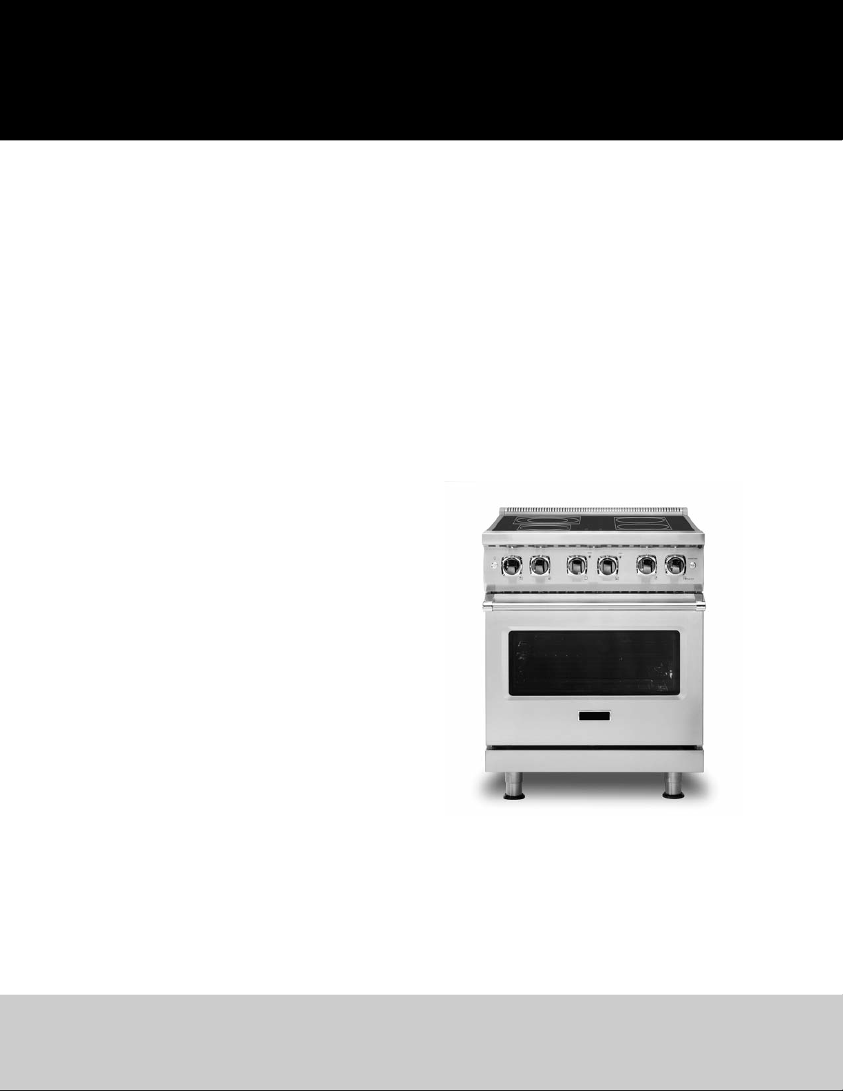
5 Series
Freestanding 30” W Electric & 30” W Induction Ranges
VER530 / CVER530
VIR530 / CVIR530
GUIDE

2
Warnings & Important Safety Instructions _____________________________________________________2
Dimensions ______________________________________________________________________________4
Specifications ____________________________________________________________________________5
Clearance Dimensions (Proximity to Cabinets) __________________________________________________6
Clearance Dimensions (Wood/Composite Overlay) ______________________________________________7
Electrical Requirements ____________________________________________________________________8
General Information _______________________________________________________________________9
Installation______________________________________________________________________________10
Door Removal ____________________________________________________________________10
Leg Installation ___________________________________________________________________10
Electrical Connection (3-wire) _______________________________________________________11
Electrical Connection (4-wire) _______________________________________________________12
Leveling/Adjustments/Alignment ____________________________________________________13
Anti-tip Device Installation __________________________________________________________14
Final Installation __________________________________________________________________16
Door Replacement and Adjustment __________________________________________________16
Performance Checklist ____________________________________________________________________17
Final Preparation_________________________________________________________________________18
Service & Registration_____________________________________________________________________18
• Before beginning, please read these instructions completely and carefully.
• Do not remove permanently affixed labels, warnings, or plates from product. This may void the warranty.
• All local and national codes and ordinances must be observed. Installation must conform with local codes or in
the absence of codes, the National Fuel Gas Code ANSIZ223.1/NFPA-54 –latest edition.
• The installer must leave these instructions with the consumer who should retain for local inspector’s use and for
future reference.
In Canada: Installation must be in accordance with the current CSA C22.1 Canadian Electrical Codes Part 1 and/or
local codes.
Table of Contents
Important
–Read and Follow!
3
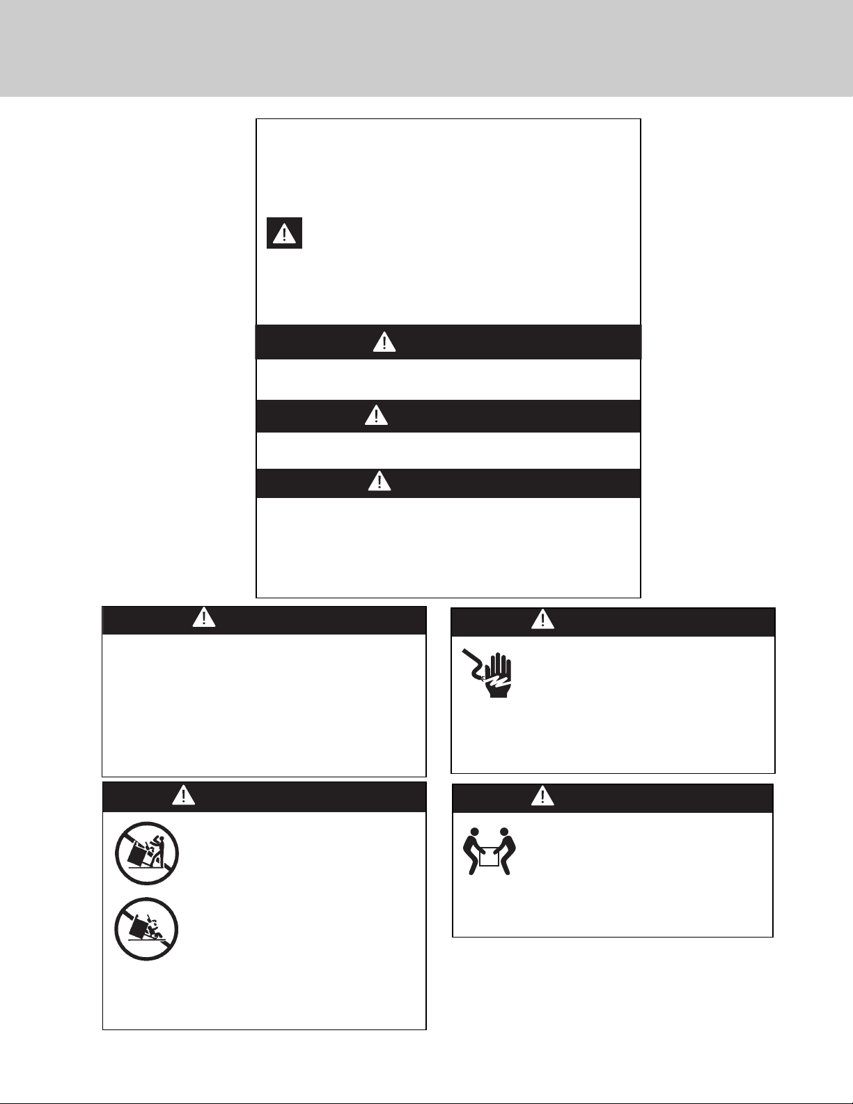
Your safety and the safety of others is very important.
We have provided many important safety
messages in this manual and on your appliance. Always
read and obey all
safety messages.
This is the safety alert symbol.
This symbol alerts you to hazards that can kill or
hurt you and others.
All safety messages will be preceded by the safety alert
symbol and the word “DANGER,” “WARNING” or
“CAUTION.” These words mean:
Hazards or unsafe practices
which WILL result in severe personal injury or death
DANGER
Hazards or unsafe practices
which COULD result in severe personal injury or death
Hazards or unsafe practices which COULD result in
minor personal injury or property damage.
All safety messages will identify the hazard, tell you how to
reduce the chance of injury, and tell you what can happen if
the instructions are not followed.
WARNING
CAUTION
Important
–Read and Follow!
DANGER
ELECTRICAL SHOCK HAZARD
To avoid risk of electrical shock, personal
injury or death; verify your appliance has
been properly grounded in accordance
with local codes or in absence of codes, with the
National Electrical Code (NEC). ANSI/NFPA 70-latest
edition.
WARNING
MOVING HAZARD
To avoid risk of severe personal injury;
this appliance requires two or more
personnel while handling and moving.
Possible use of appliance moving devices is
recommended.
WARNING
TIPPING HAZARD
To reduce the risk of the appliance
tipping, it must be secured by a properly
installed anti-tip bracket(s). To make sure
the bracket has been installed properly,
look behind the range with a flashlight
to verify proper installation engaged in
the rear top left corner of the range.
• This range can tip.
• Injuries to persons can result.
• Install anti-tip device packed with range.
• See installation instructions.
WARNING
To prevent possible damage to cabinets and cabinet
finishes, use only materials and finishes that will not
discolor or delaminate and will withstand
temperatures up to 194°F (90°C). Heat resistant
adhesive must be used if the product is to be
installed in laminated cabinetry. Check with your
builder or cabinet supplier to make sure that the
materials meet these requirements.
4
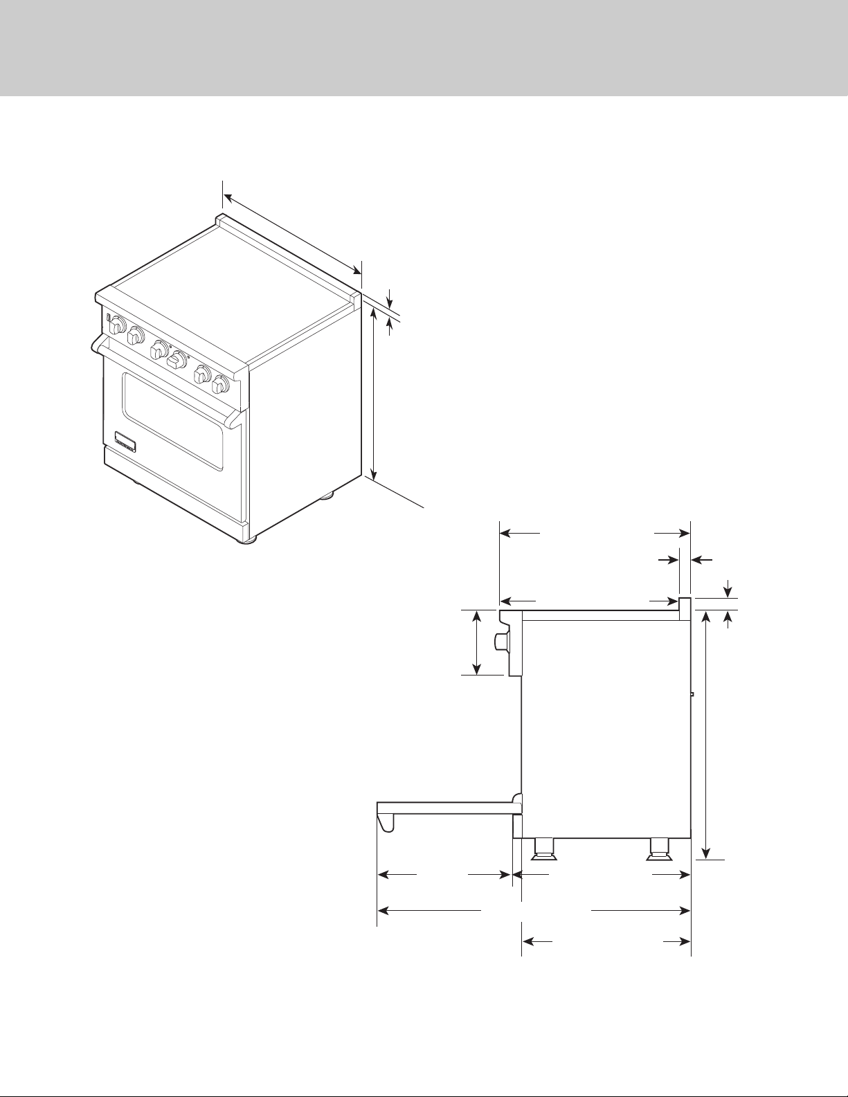
25-3/4” (65.4 cm)
45-1/8” (114.6 cm)
19-3/8”
(49.2 cm)
8-1/8”
(20.6 cm)
26-7/16” (67.2 cm)
1-5/8”
(4.1 cm)
1” (2.5 cm)
35-7/8”
(91.1 cm) min.
to
37”
(94.0 cm) max.
24-5/16” (61.8 cm)
28-1/16” (71.2 cm)
*Note: Units shown with standard island trim.
Dimensions
29-7/8”
(75.9 cm)
1”
(2.5 cm
35-7/8”
(91.1 cm) min.
to
(94.0 cm) max.
37”
)*
5
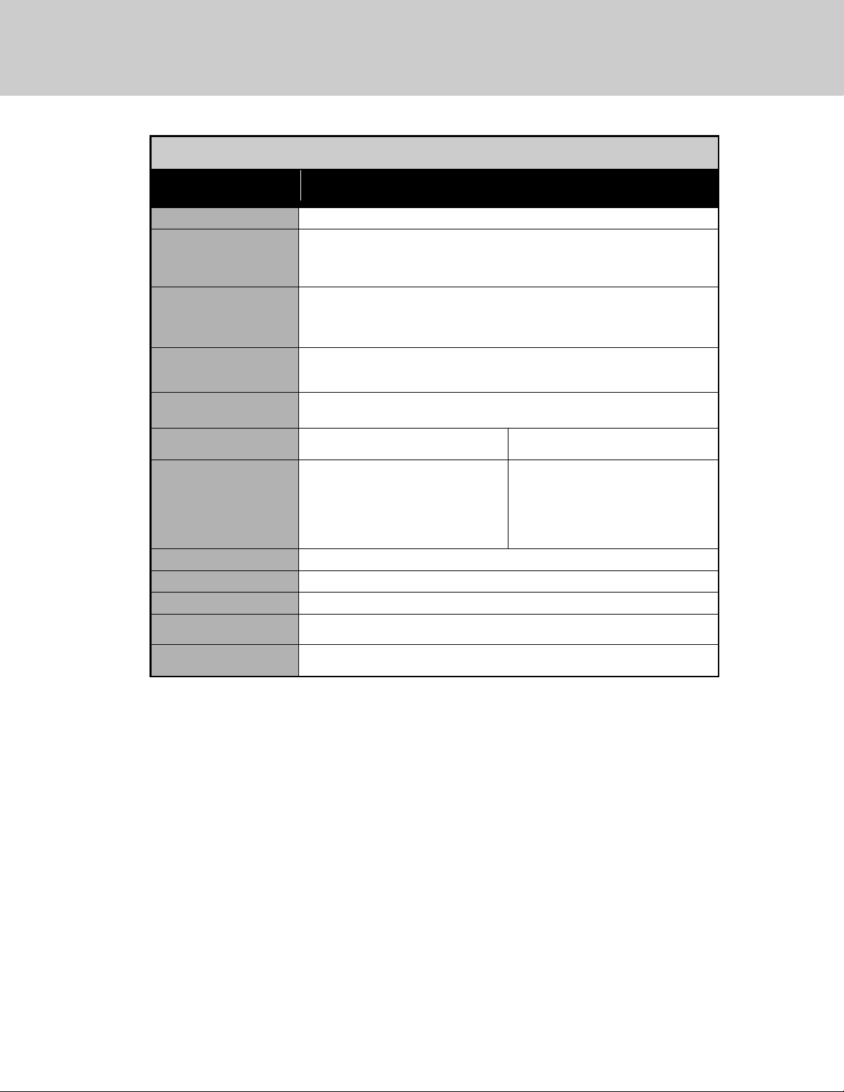
Description
VER 30” Ranges VIR 30” Ranges
Overall width
29-7/8” (75.9 cm)
Overall height To top of glass frame
35-7/8” (91.1 cm) min.
37” (94.0 cm) max.
Legs adjust 1-1/8” (2.9 cm)
Overall depth from
rear
To end of side panel—24-5/16” (61.8 cm)
To front of door—25-3/4” (65.4 cm)
To end of landing ledge—28-1/16” (71.3 cm)
To end of door handle—28-11/16” (72.9 cm)
Additions to base
height
To top of island trim—add 1” (2.5 cm)
To top of backguard—add 8” (20.3 cm)
To top of high-shelf—add 23-1/2” (59.7 cm)
Electrical
requirements
See Electrical Requirements information.
Maximum amp usage 240V—60.7 amps
208V—52.6 amps
240V—60.0 amps
208V—52.0 amps
Surface element rating
Left front
Left rear
Right front
Bridge
Right rear
1,500 watts
2,500 watts/1,000 watts
1,800 watts
800 watts
1,800 watts
3,700 watts boost / 2.300 watts
1,400 watts
1,850 watts
N/A
1,850 watts
Oven interior width
25-5/16” (64.6 cm)
Oven interior height
16-1/2” (41.9 cm)
Oven interior depth
AHAM 16-13/16” (42.7 cm) Overall—19-1/2” (49.5 cm)
Oven volume Total oven capacity—4.7 cu. ft.
Measure to AHAM standards 4.1 cu. ft.
Approximate
shipping weight
426 lbs. (193.2 kg)
Minimum clearances from adjacent combustible construction
• Cooking surface and below, i.e., 36” (91.4 cm) and below
o Sides—0”
• Above cooking surface, i.e. above 36" (91.4 cm)
o Sides—6” (15.2 cm)
o Within 6” (15.2 cm) side clearance, wall cabinets no deeper than 13” (33.0 cm) must be minimum 18” (45.7 cm) above cooking surface.
o Wall cabinets directly above product must be minimum 36” (91.4 cm) for open top burners above cooking surface.
o Rear—0” with backguard or highshelf; 0” with island trim and noncombustible rear wall; 6” (15.2 cm) with island trim and combustible
rear wall.
Specifications
6
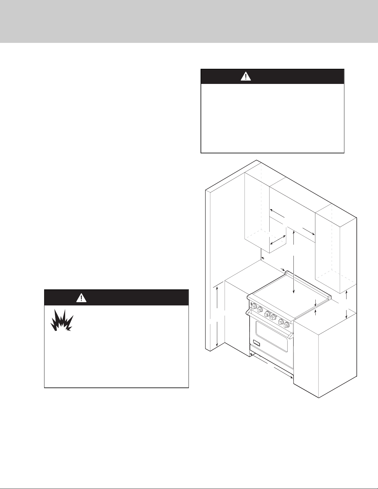
CAUTION
Burn hazard.
To avoid risk of personal injury; the use of
cabinets for storage above the appliance
may result in a potential burn hazard.
Combustible items may ignite, metallic items may
become hot and cause burns. If a cabinet storage is to
be provided the risk can be reduced by installing a
rangehood that projects horizontally a minimum 5”
(12.7 cm) beyond the bottom of cabinets.
• This range may be installed directly adjacent to
existing 36” (91.4 cm) high base cabinets.
IMPORTANT: The side trim MUST be 3/8” (.95 cm)
above the adjacent base cabinet countertop. This can
be accomplished by raising the unit using the
adjustment spindles on the legs.
• The range CANNOT be installed directly adjacent to
sidewalls, tall cabinets, tall appliances, or other side
vertical surfaces above 36” (91.4 cm) high. There must
be a minimum of 6” (15.2 cm) side clearance from the
range to such combustible surfaces above the 36” (91.4
cm) counter height.
• Within the 6” (15.2 cm) side clearance to combustible
vertical surfaces above 36” (91.4 cm), the maximum
wall cabinet depth must be 13” (33.0 cm) and wall
cabinets within this 6” (15.2 cm) side clearance must be
18” (45.7 cm) above the 36” (91.4 cm) high countertop.
• Wall cabinets above the range must be a minimum of
42” (106.7 cm) above the range cooking surface for the
full width of the range. This minimum requirement
does not apply if a range hood is installed over the
cooking surface.
CAUTION
To prevent possible damage to cabinets and cabinet
finishes, use only materials and finishes that will not
discolor or delaminate and will withstand
temperatures up to 194°F (90°C). Heat and moisture
resistant adhesive must be used if the product is to
be installed in laminated cabinetry. Check with your
builder or cabinet supplier to make sure that the
materials meet these requirements.
Note: Minimum clearance for back wall is 0” with backguard or highshelf.
Note: If a range hood is installed, wall cabinets above the range have
a different minimum clearance height.
Clearance Dimensions (Proximity to Cabinets)
13” max.
33.0 cm)
(
6” min.
(15.2 cm)
29-7/8”
(75.9 cm)
42” min.
(106.7 cm)
18” min.
36”
91.4 cm)
(
30”
(76.2 cm)
(opening width)
3/8”
(0.95 cm)
(45.7 cm
)
 Loading...