

Viking VDSC536T-6B, VDSC530 Series, VDSC536T-4G, VDSC536T-4Q, VDSC548T-6G Service Manual
...
Service
Manual
This manual is to be used by qualified appliance technicians only.
Viking does not assume any responsibility for property damage
or personal injury for improper service procedures done by an
unqualified person.
Electronic
Preferred Service
This Base Manual covers general and
specific information including, but not
limited to the following models:
Control Dual
Fuel Range
VDSC530T–4B
VDSC536T–6B
VDSC536T–4G
VDSC536T–4Q
VDSC548T–6G
VDSC548T–6Q
VDSC548T–4GQ
SMC-0012A
June, 2011

Table of Contents
Description Page
Important Information .................................................. 4
Safety Information ........................................................ 4
WARRANTY INFORMATION
Warranty Information .................................................... 5
Warranty Service Information .......................................6
GENERAL INFORMATION
Specifications ............................................................... 7
Dimensions ................................................................. 10
Warnings .....................................................................12
Electrical and Gas Requirements ................................ 15
Model–Serial Number Matrix ..................................... 16
OPERATION
Settings and Functions ...............................................17
Lighting Burners ....................................................... 17
Surface Burner Automatic Ignition ...........................17
Griddle/Simmer Plate ............................................... 17
Char-Grill .................................................................. 17
Settings and Functions–30” Oven .............................. 18
Left Display Window ................................................ 18
Clock, Time Function and Temp Probe Display ....... 18
Display Time of Day .................................................18
Right Display Window .............................................. 18
Temperature and Oven Function.............................. 18
Temperature Display................................................. 18
Clock/Probe Setting Time of Day ............................. 19
Min/Sec Timer .......................................................... 19
Cook Time ................................................................ 19
Stop Time ................................................................. 20
To Set Delayed Start ................................................. 20
Meat Probe ............................................................... 21
Set Oven Function .................................................... 21
Function Displays (General) ...................................... 21
Set Oven Temperature ............................................. 22
Self-Clean ................................................................. 23
Normal Operation .................................................... 23
Hold Mode ............................................................... 24
Sabbath Mode .......................................................... 24
Showroom Mode ...................................................... 24
Control Lock ............................................................. 24
Cycle Charts Right Oven (Bake Cycle) ...................... 25
Cycle Charts Right Oven
(Convection Bake Cycle) ......................................... 26
Cycle Charts Right Oven (TruConvec Cycle) ............27
Cycle Charts Right Oven
(Convection Roast Cycle) ........................................ 27
Cycle Chart Right Oven
(Convection Broil Max Cycle) ................................28
Cycle Chart Right Oven
(Convection Broil Medium Cycle) ........................... 28
Cycle Chart Right Oven
(Convection Broil Low Cycle) .................................. 28
Cycle Charts Right Oven (Hi Broil Cycle) .................. 29
Cycle Charts Right Oven (Medium Broil Cycle) ........ 29
Cycle Charts Right Oven (Low Broil Cycle) ...........29
© 2011 Viking Preferred Service
Description Page
Cycle Charts Right Oven (Auto Roast Cycle) ............ 30
Cycle Charts Right Oven (Defrost Cycle) .................. 30
Cycle Charts Right Oven (Dehydrate Cycle) ............. 30
Cycle Charts Right Oven (Proof Cycle) ..................... 31
Cycle Charts Right Oven (Self-Clean Cycle) ............. 31
Control Operation Left Oven (48” Model) Grill
and Griddle ............................................................32
Cycle Charts Left Oven (Bake Cycle) ........................ 33
Cycle Charts Left Oven
(Convection Bake Cycle) ......................................... 34
Cycle Charts Left Oven (TruConvec Cycle) ............... 34
Cycle Charts Left Oven
(Convection Roast Cycle) ........................................ 35
Cycle Chart Left Oven (Convection Broil Cycle) ....... 35
Cycle Chart Left Oven (Hi Broil Cycle) ...................... 35
Cycle Chart Left Oven (Low Broil Cycle) ................... 36
Cycle Chart Left Oven (Proof Cycle) ......................... 36
Cycle Chart Left Oven (Self-Clean Cycle) ................. 36
BAKE ........................................................................37
CONV BAKE ............................................................. 37
TRU CONV ...............................................................37
CONC ROAST .......................................................... 37
CONV BROIL ............................................................ 37
HI BROIL ................................................................... 38
MED BROIL (30” oven only) ..................................... 38
LOW BROIL .............................................................. 38
DEHYDRATE ............................................................. 38
PROOF .....................................................................38
DIAGNOSTICS
Error Codes–30” Oven ............................................... 39
Error Codes–18” Oven ............................................... 40
Temperature Range and Default ................................ 42
User Settings–30” Oven ............................................. 43
Offset Temperature Adjustment (both ovens) ............ 44
Diagnostics and Testing ............................................. 45
Check Control Version and Entering
Diagnostic Program ................................................ 45
Selecting EOC Test ................................................... 46
RTD Meat Probe ....................................................... 47
Cycle (VDSC548T–left oven only) ............................. 48
Set Point (VDSC548T–left oven only) ....................... 49
Inner Bake................................................................. 50
Outer Bake ............................................................... 50
Inner Broil ................................................................. 51
Outer Broil ................................................................ 52
Convection ............................................................... 52
Convection Fan High Forward .................................. 53
Convection Fan Low Forward ................................... 53
Cool Fan High ..........................................................54
Cool Fan Low ........................................................... 54
Cooling Fan Speed High .......................................... 55
Cooling Fan Speed Low ........................................... 55
Oven Light ................................................................ 56
Convection Fan Low Reverse ................................... 57
Convection Fan High Reverse .................................. 57
2

Table of Contents
Description ..................................................... Page
Door Latch ................................................................ 58
Heat Light (VDSC548T–left oven only) ..................... 59
Clean Light (VDSC548T–left oven only) ...................59
Door Switch .............................................................. 60
Light Switch .............................................................. 60
Exit ............................................................................ 61
Auto Tests ................................................................. 62
Cycles (Cook Count/Clean Count) ........................... 64
Errors ........................................................................ 66
Display Tests ............................................................. 68
Ambient Temperature
(temperature at UI board) ....................................... 70
SERVICE DIAGNOSTICS AND PROCEDURES
Parts Location Control Board ..................................... 71
Parts Location Control Board–VDSC548T
(left oven) .................................................................. 72
Control Board Test Points ........................................... 73
Control Board Diagnosis ............................................ 74
Line Break Relay ....................................................... 74
Bake Element ........................................................... 74
Bake Relay (Inner and Outer) .................................... 75
Broil Element ............................................................ 75
Broil Relay (Inner and Outer) .................................... 76
Inner Broil Relay ........................................................76
Outer Broil Relay ...................................................... 76
Convection Element ................................................. 76
Convection Relay ...................................................... 77
Power Output Test .................................................... 77
Cooling Fan .............................................................. 77
Fan Relay .................................................................. 78
Convection Fan ........................................................79
Convection Fan Operation ....................................... 79
Testing Control Board............................................... 80
Testing The Capacitor .............................................. 80
Testing Fan Motor .................................................... 80
Door Lock Assembly ................................................. 81
Testing Lock Motor ................................................... 81
Testing Latch Switches .............................................. 81
Checking The Door Lock Position Switches ............. 82
RTD Sensor ............................................................... 83
RTD Characteristics ..................................................83
IRIS Spark Module Test ............................................. 83
Output Power ........................................................... 83
Parts Location Range Top–VDSC530T........................ 84
Parts Location Range Top–VDSC536T........................ 85
Parts Location Range Top–VDSC548T........................ 86
Landing Ledge–VDSC530T ........................................ 87
Landing Ledge–VDSC536T ........................................ 88
Landing Ledge–VDSC548T ........................................ 90
Left Oven Thermostat–VDSC548T ............................. 92
Left Oven Function Selector–VDSC548T ................... 92
Char-Grill–VDSC536T-4Q, VDSC548T-6Q,
VDSC536T-4GQ, ....................................................... 93
Griddle–VDSC536T-4G, VDSC548T-6G,
VDSC536T-4GQ, ....................................................... 94
Description ...................................................... Page
Main Top Access ......................................................... 95
Surface Igniter ............................................................ 96
Orifice Holder ............................................................. 97
Pressure Regulator ...................................................... 97
Manifold Pipe ............................................................. 98
IRIS Spark Module ...................................................... 99
Burner Valve ............................................................... 99
User Interface ...........................................................100
Oven Light Switch ....................................................100
Door Lock Assembly ................................................. 101
Door Switch .............................................................. 101
Parts Location Oven–VDSC530T, VDSC536T,
VDSC548T (Right Oven) ......................................... 102
Parts Location Oven–VDSC548T (Left Oven) ...........104
Parts Location Back–VDSC530T, VDSC536T ............ 105
Parts Location Back–VDSC548T ............................... 106
Door Removal ........................................................... 107
RTD Sensor ............................................................... 108
Rack Support ............................................................ 108
Convection Fan Assembly ........................................ 109
Convection Fan Cover .............................................. 109
Convection Fan ........................................................109
Convection Element ................................................. 110
Smoke Eliminator ..................................................... 110
Interior Bulb Replacement ........................................ 110
Broil Element ............................................................ 111
Bake Element ........................................................... 112
Control Board Access ............................................... 113
Control Board Removal ............................................ 113
Main Back Access–VDSC530T .................................. 114
Main Back Access–VDSC536T .................................. 115
Main Back Access–VDSC548T .................................. 116
Terminal Block .......................................................... 117
Oven Cooling Fan .................................................... 117
Left Oven Cooling Fan–VDSC548T .......................... 118
Hall Effect Sensor .....................................................118
Troubleshooting Guide ............................................. 120
WIRING DIAGRAMS
Control Fan Current Flow ......................................... 122
Wiring Schematic–VDSC530T-4B ............................. 124
Wiring Schematic–VDSC536T-4G ............................. 125
Wiring Schematic–VDSC536T-4Q ............................ 126
Wiring Schematic–VDSC536T-6B ............................. 127
Wiring Schematic–VDSC548T-4GQ–Left Oven ........128
Wiring Schematic–VDSC548T-6G–Left Oven ...........129
Wiring Schematic–VDCS548T-6Q–Left Oven ........... 130
Wiring Schematic–VDCS548T-4GQ/6G
Right Oven ............................................................. 131
Wiring Schematic–VDCS548T-6Q–RIght Oven ........ 132
© 2011 Viking Preferred Service
3
Important Information
SAVE THESE INSTRUCTIONS
REVIEW ALL SERVICE INFORMATION IN THE APPROPRIATE SERVICE MANUAL AND
TECHNICAL SHEETS BEFORE BEGINNING REPAIRS.
Pride and workmanship go into every product to provide our customers with quality appliances. It is possible,
however, that during the lifetime of a product, service may be required. Products should be serviced only by
a qualified authorized service technician who is familiar with the safety procedures required to perform the
repair and is equipped with the proper tools, parts, testing instruments, and the appropriate service manual.
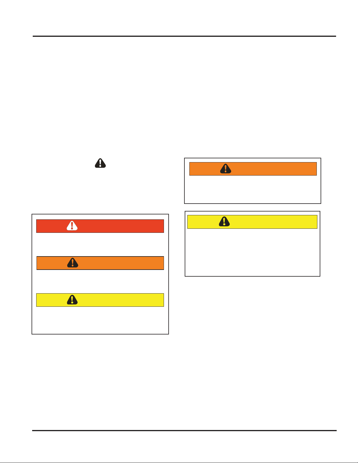
Safety Information
We have provided many important safety messages
throughout this manual and on the appliance.
ALWAYS read and obey all safety messages. This is
a safety alert symbol.
All safety messages will identify the hazard, tell
you how to reduce the chance of injury, and inform
you what can happen if the instructions are not
followed.
This symbol alerts personnel to hazards that can
kill or hurt you and others. All safety messages will
be preceded by a safety alert symbol and the word
“DANGER”, “WARNING” or “CAUTION”. These
words mean:
DANGER
Immediate hazards which WILL result in severe
personal injury or death.
WARNING
Hazards or unsafe practices which COULD
result in severe personal injury or death.
CAUTION
Hazards or unsafe practices which COULD
result in minor personal injury, product or
property damage.
WARNING
To avoid risk of serious injury or death,
repairs should not be attempted by
unauthorized personnel.
CAUTION
VIKING will not be responsible for any injury
or property damage from improper service
procedures. If performing service on your
own product, you must assume responsibility
for any personal injury or property damage
which may result.
To locate an authorized service agent, call:
Viking Customer Service
Phone No. 1-888-845-4641
Address your written correspondence to:
Viking Preferred Service
1803 HWY 82 West
Greenwood, MS 38930
© 2011 Viking Preferred Service
4

Warranty Information
Professional Series
Freestanding Dual Fuel Ranges
Freestanding dual fuel ranges and all of their component parts, except as detailed below*, are warranted to be free
from defective materials or workmanship in normal household use for a period of twelve (12) months from the date
of original retail purchase. Viking Range Corporation, warrantor, agrees to repair or replace, at its option, any part
which fails or is found to be defective during the warranty period.
*Glass (including light bulbs), painted and decorative items are warranted to be free from defective materials or
workmanship for a period of ninety (90) days from the date of original retail purchase. ANY DEFECTS MUST BE
REPORTED TO THE SELLING DEALER WITHIN NINETY (90) DAYS FROM DATE OF ORIGINAL RETAIL PURCHASE.
Viking Range Corporation uses the most up-to-date processes and best materials available to produce all color
finishes. However, slight color variation may be noticed because of the inherent differences in painted parts and
porcelain parts as well as differences in kitchen lighting, product locations, and other factors.
Five Year Limited Warranty
One Year Full Warranty
Any surface burner, griddle burner, grill burner, or oven burner which fails due to defective materials or workmanship
in normal household use during the second through fifth year from the date of original retail purchase will be
repaired or replaced, free of charge for the part itself, with the owner paying all other costs, including labor.
Ten Year Limited Warranty
Any porcelain oven or porcelain inner door panel which rusts through due to defective materials or workmanship
in normal household use during the second through the tenth year from the date of original retail purchase will be
repaired or replaced, free of charge for the part itself, with the owner paying all other costs, including labor.
Ninety (90) Day Residential Plus Warranty
This warranty applies to applications where use of the product extends beyond normal residential use. Examples
are, but not limited to, bed and breakfasts, fire stations, private clubs, churches, etc. This warranty excludes all
commercial locations such as restaurants, food service locations and institutional food service locations.
This warranty extends to the original purchaser of the product warranted hereunder and to each transferee owner
of the product during the term of the warranty.
This warranty shall apply to products purchased and located in the United States and Canada. Products must be
purchased in the country where service is requested. Warranty labor shall be performed by an authorized Viking
Range Corporation service agency or representative. Warranty shall not apply to damage resulting from abuse,
accident, natural disaster, loss of electrical power to the product for any reason, alteration, improper installation,
improper operation or repair or service to the product by anyone other than an authorized Viking Range
Corporation service agency or representative. Warranty shall not apply to damage resulting from indoor units
being used in outdoor situations. This warranty does not apply to commercial usage. This warranty does not
cover any food or medicine loss due to product failure. Warrantor is not responsible for consequential or
incidental damage whether arising out of breach of warranty, breach of contract, or otherwise. Some jurisdictions
do not allow the exclusion or limitation of incidental or consequential damages, so the above limitation or
exclusion may not apply to you.
Owner shall be responsible for proper installation, providing normal care and maintenance, providing proof of
purchase upon request, and making the appliance reasonably accessible for service. If the product or one of its
component parts contains a defect or malfunction during the warranty period, after a reasonable number of
attempts by the warrantor to remedy the defects or malfunctions, the owner is entitled to either a refund or
replacement of the product or its component part or parts. Replacement of a component part includes its free
installation. Warrantor’s liability on any claim of any kind, with respect to the goods or services covered hereunder,
shall in no case exceed the price of the goods or service or part there of which gives rise to the claim.
111 Front Street, Greenwood, Mississippi (MS) 38930 USA
For more product information, call 1-888-VIKING1 (845-4641), or visit our
© 2011 Viking Preferred Service
VIKING RANGE CORPORATION
662-455-1200
web site at http://www.vikingrange.com
5

Warranty Information
WARRANTY SERVICE
Under the terms of this warranty, service must be performed by a factory authorized Viking Range Corporation
service agent or representative. Service will be provided during normal business hours, and labor performed
at overtime or premium rates shall not be covered by this warranty. To obtain warranty service, contact the dealer
from whom the product was purchased, an authorized Viking Range Corporation service agent, or Viking Range
Corporation. Provide model and serial number and date of original purchase. For the name of your nearest
authorized Viking Range Corporation service agency, call the dealer from whom the product was purchased or
Viking Range Corporation. IMPORTANT: Retain proof of original purchase to establish warranty period.
The return of the Owner Registration Card is not a condition of warranty coverage. You should, however, return the
Owner Registration Card so that Viking Range Corporation can contact you should any question of safety arise which
could affect you.
Any implied warranties of merchantability and fitness applicable to the described halogen elements are limited
in duration to the period of coverage of the applicable express written limited warranties set forth above. Some
jurisdictions do not allow limitations on how long an implied warranty lasts, so the above limitation may not apply to
you. This warranty gives you specific legal rights, and you may also have other rights which may vary from jurisdiction
to jurisdiction.
£££ÊÀÌÊ-ÌÀiiÌÊUÊÀ
Specification subject to change without notice.
VIKING RANGE CORPORATION
iiÜ`]ÊÃÃÃë«ÊÎnÎäÊ1-
(662) 455-1200
www.vikingrange.com
© 2011 Viking Preferred Service
6
General InformationGeneral Information
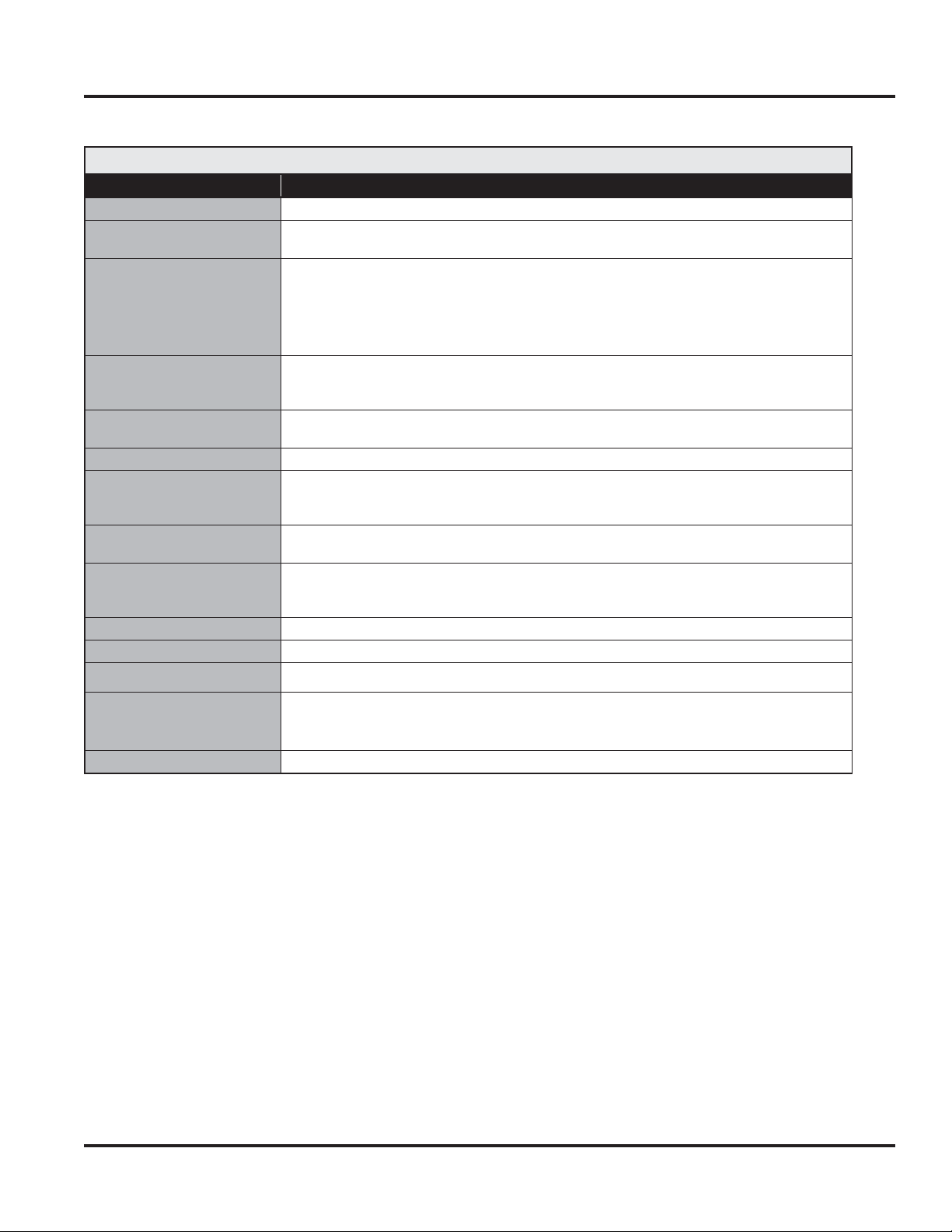
Specifications*
30” Electronic Control Dual Fuel Range
Description VDSC530T–4B
Overall width
Overall height
Overall depth from rear
To end of side panel
To front of door
To end of landing ledge
To end of door handle
Additions to base height
Gas requirements
Gas manifold pressure
Electrical requirements
Maximum amp usage
Surface burner rating
Natural
LP
Oven interior width
Oven interior height
Oven interior depth
To top of side trim—35-7/8” (91.1 cm) min. 37” (94.0 cm) max.
To top of island trim—add 1” (2.5 cm)
To top of backguard—add 8” (20.3 cm)
To top of high shelf—add 23-1/2” (59.7 cm)
Shipped Natural or LP/Propane, field convert with conversion kit (purchased separately);
accepts standard residential 1/2” (1.3 cm) ID gas service line.
Natural 5.0” W.C.P./ Liquid Propane L/P 10.0” W.C.P.
240-208 VAC 60 Hz electrical connection box on product, connect with locally supplied
3-wire, flexible cord or “pigtail” rated 40 amp 125-250 VAC minimum.
Cord must be agency approved for use with household electric ranges.
18,500 BTU (5.4 kW)/16,600 BTU (4.9 kW)
15,000 BTU (4.4 kW)/12,500 BTU (3.7 kW)
Oven(s) interior height 16-1/2” (41.9 cm)
29-7/8” (75.9 cm)
Legs adjust—1-1/8” (2.9 cm)
24-5/16” (61.8 cm)
25-3/4” (65.4 cm)
28-1/16” (71.2 cm)
28-11/16” (72.9 cm)
240V—25.4 amps
208V—22.9 amps
25-5/16” (64.6 cm)
16-1/2” (41.9 cm)
Oven volume
Overall
AHAM
Approximate shipping weight
4.7 cu. ft.
4.1 cu. ft.
565 lbs. (254.3 kg)
*Go to vikingrange.com for the latest specifications.
Minimum clearances from adjacent combustible construction:
Below cooking surface (36” [91.4 cm] and below)
Ê UÊ-`iÃÊÊä»
Ê UÊ/«Ê}À>ÌiÊÃÕ««ÀÌÊÊÎȻʣ°{ÊV®
Above cooking surface (above 36” [91.4 cm])
Ê UÊ-`iÃÊÊȻʣx°ÓÊV®
Ê UÊÊ7ÌÊȻʣx°ÓÊV®ÊÃ`iÊVi>À>Vi]ÊÜ>ÊV>LiÌÃÊÊ`ii«iÀÊÌ>ʣλÊÎΰäÊV®ÊÕÃÌÊLiÊÕÊ
18” (45.7 cm) above cooking surface
Ê UÊÊ7>ÊV>LiÌÃÊ`ÀiVÌÞÊ>LÛiÊ«À`ÕVÌÊÕÃÌÊLiÊ>ÊÕÊvÊ{ӻʣäÈ°ÇÊV®Ê>LÛiÊV}ÊÃÕÀv>Vi
Ê UÊÊ,i>ÀÊÊä»ÊÜÌÊn»ÊL>V}Õ>À`ÊÀÊ}h shelf; 0” with island trim and non-combustible rear wall
Ê UÊÊȻʣx°ÓÊV®ÊÜÌÊÃ>`ÊÌÀÊ>`ÊVLÕÃÌLiÊÀi>ÀÊÜ>
© 2011 Viking Preferred Service
7
7
General Information
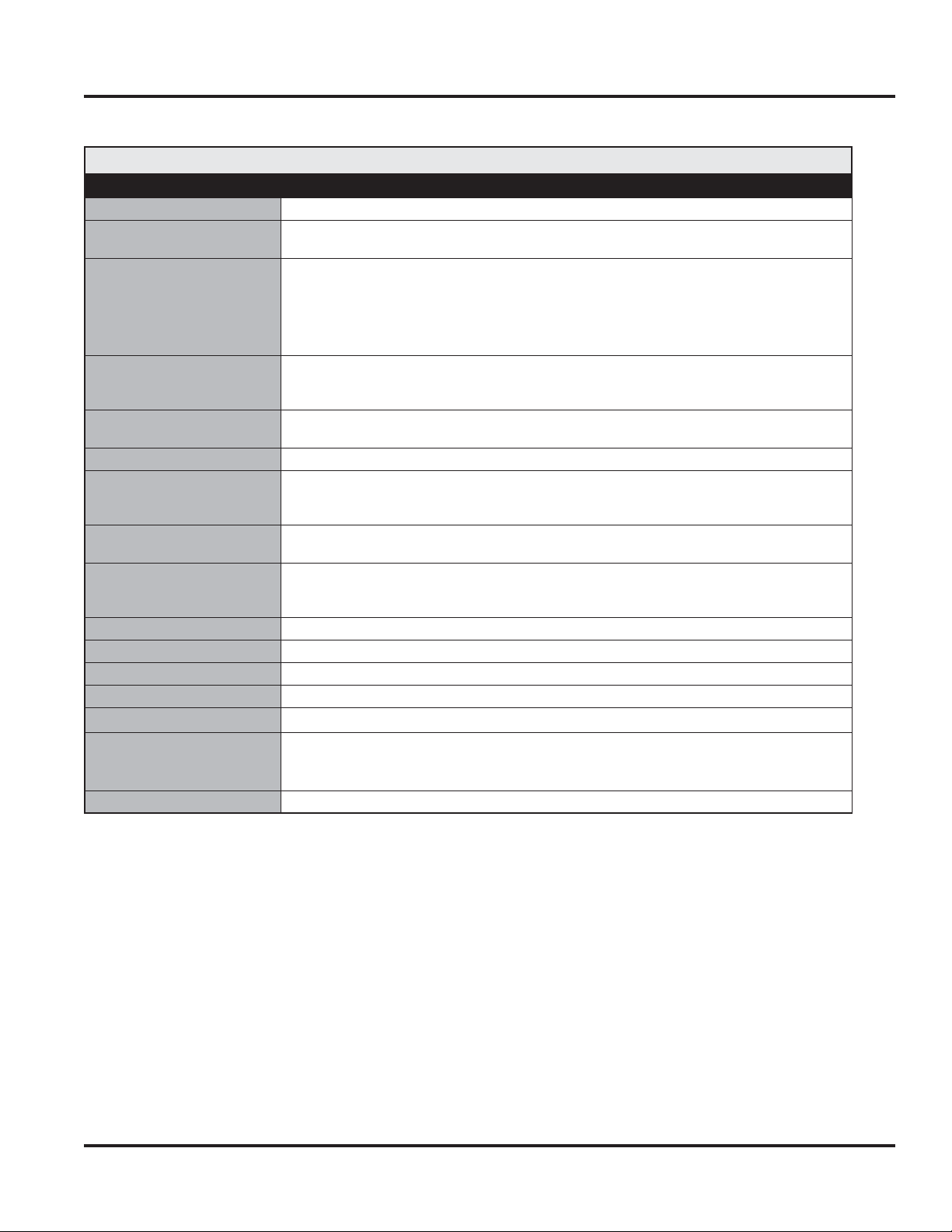
Specifications*
36” Electronic Control Dual Fuel Range
Description VDSC536T–6B/VDSC536T–4G/VDSC536T–4Q
Overall width
Overall height
Overall depth from rear
To end of side panel
To front of door
To end of landing ledge
To end of door handle
Additions to base height
Gas requirements
Gas manifold pressure
Electrical requirements
Maximum amp usage
Surface burner rating
Natural
LP
Griddle Burner Rating
Grill Burner Rating
Oven interior width
Oven interior height
Oven interior depth
Oven volume
Overall
AHAM
Approximate shipping weight
Shipped Natural or LP/Propane, field convert with conversion kit (purchased separately);
240-208 VAC 60 Hz electrical connection box on product, connect with locally supplied
To top of side trim—35-7/8” (91.1 cm) min. 37” (94.0 cm) max.
To top of high shelf—add 23-1/2” (59.7 cm)
accepts standard residential 1/2” (1.3 cm) ID gas service line.
Natural 5.0” W.C.P./ Liquid Propane L/P 10.0” W.C.P.
3-wire, flexible cord or “pigtail” rated 40 amp 125-250 VAC minimum.
Cord must be agency approved for use with household electric ranges.
15,000 BTU Nat./12,500 BTU LP/Propane (4.4 kW Nat/ 3.7 kW LP)
18,000 BTU Nat./16,000 BTU LP/Propane (5.3 kW Nat/ 4.7 kW LP)
Overall—19-1/2” (49.5 cm) AHAM 16-13/16” (42.7 cm)
*Go to vikingrange.com for the latest specifications.
To top of island trim—add 1” (2.5 cm)
To top of backguard—add 8” (20.3 cm)
18,500 BTU (5.4 kW)/16,600 BTU (4.9 kW)
15,000 BTU (4.4 kW)/12,500 BTU (3.7 kW)
35-7/8” (91.1 cm)
Legs adjust—1-1/8” (2.9 cm)
24-5/16” (61.8 cm)
25-3/4” (65.4 cm)
28-1/16” (71.2 cm)
28-11/16” (72.9 cm)
240V—28.5 amps
208V—24.7 amps
25-5/16” (64.6 cm)
16-1/2” (41.9 cm)
5.6 cu. ft.
4.9 cu. ft.
500 lbs. (225 kg)
Minimum clearances from adjacent combustible construction:
Below cooking surface (36” [91.4 cm] and below)
Ê UÊ-`iÃÊÊä»
Ê UÊ/«Ê}À>ÌiÊÃÕ««ÀÌÊÊÎȻʣ°{ÊV®
Above cooking surface (above 36” [91.4 cm])
Ê UÊ-`iÃÊÊȻʣx°ÓÊV®
Ê UÊÊ7ÌÊȻʣx°ÓÊV®ÊÃ`iÊVi>À>Vi]ÊÜ>ÊV>LiÌÃÊÊ`ii«iÀÊÌ>ʣλÊÎΰäÊV®ÊÕÃÌÊLiÊÕÊ
18” (45.7 cm) above cooking surface
Ê UÊÊ7>ÊV>LiÌÃÊ`ÀiVÌÞÊ>LÛiÊ«À`ÕVÌÊÕÃÌÊLiÊ>ÊÕÊvÊ{ӻʣäÈ°ÇÊV®Ê>LÛiÊV}ÊÃÕÀv>Vi
Ê UÊÊ,i>ÀÊÊä»ÊÜÌÊn»ÊL>V}Õ>À`ÊÀÊ}h shelf; 0” with island trim and non-combustible rear wall
Ê UÊÊȻʣx°ÓÊV®ÊÜÌÊÃ>`ÊÌÀÊ>`ÊVLÕÃÌLiÊÀi>ÀÊÜ>
© 2011 Viking Preferred Service
8
8
General Information
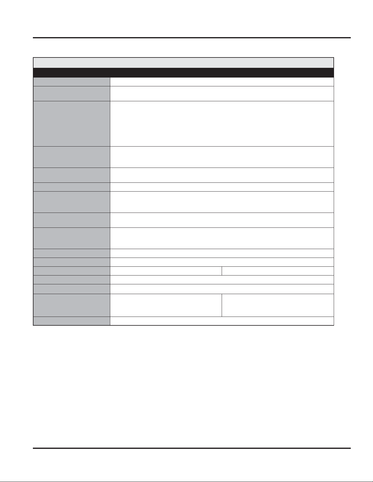
Specifications*
48” Electronic Control Dual Fuel Range
Description VDSC548T–6G/VDSC548T–6Q/VDSC548T–4GQ
Overall width
Overall height
Overall depth from rear
To end of side panel
To front of door
To end of landing ledge
To end of door handle
Additions to base height
Gas requirements
Gas manifold pressure
Electrical requirements
Maximum amp usage
Surface burner rating
Natural
LP
Griddle Burner Rating
Grill Burner Rating
Oven interior width
Oven interior height
Oven interior depth
Oven volume
Overall
AHAM
Approximate shipping weight
*Add 3/4” (1.9 cm) to overall depth for models installed against a combustible wall.
Shipped Natural or LP/Propane, field convert with conversion kit (purchased separately);
240-208 VAC 60 Hz electrical connection box on product, connect with locally supplied
To top of side trim—35-7/8” (91.1 cm) min. 37” (94.0 cm) max.
To top of high shelf—add 23-1/2” (59.7 cm)
accepts standard residential 1/2” (1.3 cm) ID gas service line.
Natural 5.0” W.C.P./ Liquid Propane L/P 10.0” W.C.P.
3-wire, flexible cord or “pigtail” rated 40 amp 125-250 VAC minimum.
Cord must be agency approved for use with household electric ranges.
15,000 BTU Nat./12,500 BTU LP/Propane (4.4 kW Nat/ 3.7 kW LP)
18,000 BTU Nat./16,000 BTU LP/Propane (5.3 kW Nat/ 4.7 kW LP)
Left—13-3/4” (34.9 cm) Right—25-5/16” (64.6 cm)
Overall—19-1/2” (49.5 cm) AHAM 16-13/16” (42.7 cm)
Left—2.6 cu. ft.
Left—2.2 cu. ft.
*Go to vikingrange.com for the latest specifications.
To top of island trim—add 1” (2.5 cm)
To top of backguard—add 8” (20.3 cm)
18,500 BTU (5.4 kW)/16,600 BTU (4.9 kW)
15,000 BTU (4.4 kW)/12,500 BTU (3.7 kW)
47-7/8” (121.6 cm)
Legs adjust—1-1/8” (2.9 cm)
24-5/16” (61.8 cm)
25-3/4” (65.4 cm)
28-1/16” (71.2 cm)
28-11/16” (72.9 cm)
240V—37 amps
208V—32 amps
16-1/2” (41.9 cm)
Right— 4.7 cu. ft.
Right—4.1 cu. ft.
575 lbs. (258.8 kg)
Minimum clearances from adjacent combustible construction:
Below cooking surface (36” [91.4 cm] and below)
Ê UÊ-`iÃÊÊä»
Ê UÊ/«Ê}À>ÌiÊÃÕ««ÀÌÊÊÎȻʣ°{ÊV®
Above cooking surface (above 36” [91.4 cm])
Ê UÊ-`iÃÊÊȻʣx°ÓÊV®
Ê UÊÊ7ÌÊȻʣx°ÓÊV®ÊÃ`iÊVi>À>Vi]ÊÜ>ÊV>LiÌÃÊÊ`ii«iÀÊÌ>ʣλÊÎΰäÊV®ÊÕÃÌÊLiÊÕÊ
18” (45.7 cm) above cooking surface
Ê UÊÊ7>ÊV>LiÌÃÊ`ÀiVÌÞÊ>LÛiÊ«À`ÕVÌÊÕÃÌÊLiÊ>ÊÕÊvÊ{ӻʣäÈ°ÇÊV®Ê>LÛiÊV}ÊÃÕÀv>Vi
Ê UÊÊ,i>ÀÊÊä»ÊÜÌÊn»ÊL>V}Õ>À`ÊÀÊ}h shelf; 0” with island trim and non-combustible rear wall
Ê UÊÊȻʣx°ÓÊV®ÊÜÌÊÃ>`ÊÌÀÊ>`ÊVLÕÃÌLiÊÀi>ÀÊÜ>
© 2011 Viking Preferred Service
9
9
General Information
.
.
General Information
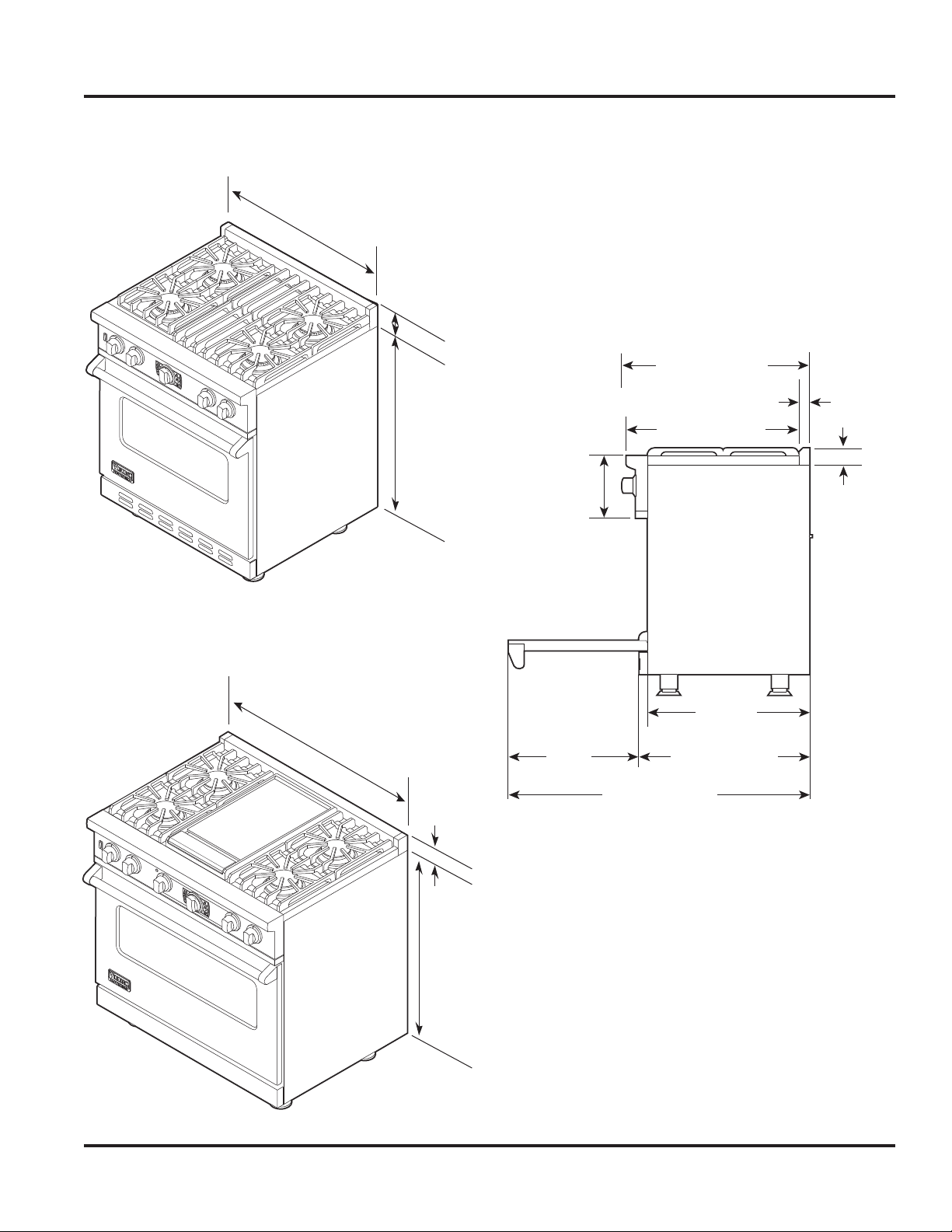
Dimensions–VDSC530T
29-7/8”
(75.9 cm)
1”
(2.5 cm)
35-7/8”
(91.1 cm) min
to
(94.0 cm) max
37”
8-1/8”
(20.6 cm)
28-1/16” (71.2 cm)
26-1/16” (67.2 cm)
1-5/8”
(4.1 cm)
1”
(2.5cm)
Dimensions–VDSC536T
35-7/8”
(91.1 cm)
24-5/16”
(61.8 cm)
19-3/8”
(49.2 cm)
1”
(2.5 cm)
35-7/8”
(91.1 cm) min.
to
(94.0 cm) max.
37”
45-1/8” (114.6 cm)
25-3/4” (65.4 cm)
© 2011 Viking Preferred Service
10
10
General Information
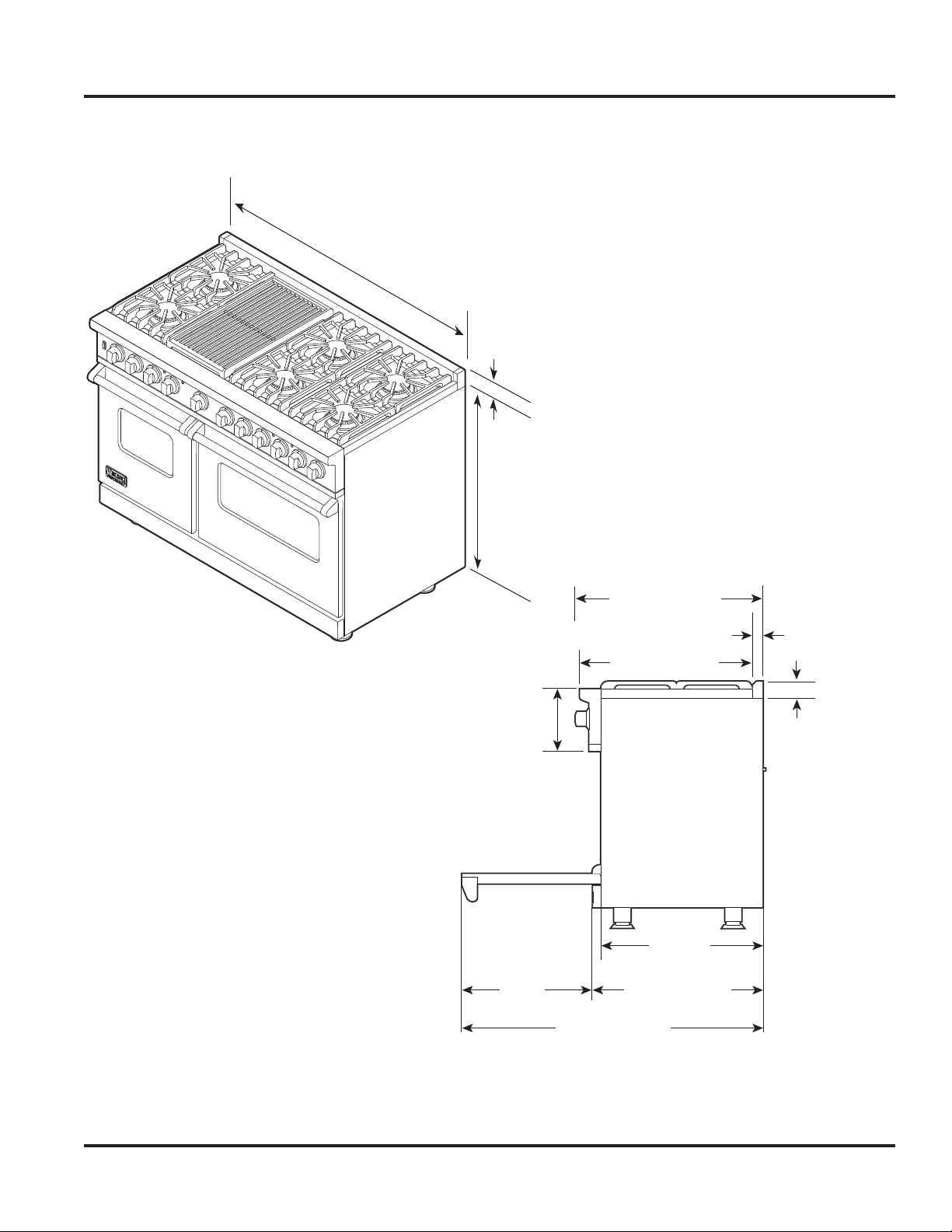
Dimensions–VDSC548T
47-7/8”
(121.6 cm)
1”
(2.5 cm)
35-7/8”
(91.1 cm) min.
to
(94.0 cm) max.
37”
8-1/8”
(20.6 cm)
19-3/8”
(49.2 cm)
28-1/16” (71.2 cm)
26-1/16” (67.2 cm)
24-5/16”
25-3/4” (65.4 cm)
45-1/8” (114.6 cm)
1-5/8”
(4.1 cm)
1”
(2.5cm)
(61.8 cm)
© 2011 Viking Preferred Service
11
11
General Information
General Information
Warnings
Read and follow all instructions before using this
appliance to prevent the potential risk of fire,
electric shock, personal injury, or damage to the
appliance as a result of improper usage of the
appliance. Use appliance only for its intended
purpose as described in this manual.
WARNING
To avoid risk of property damage, personal
injury or death, follow information in this
manual exactly to prevent a fire or explosion.
To ensure proper and safe operation: Appliance
must be properly installed and grounded by a
qualified technician. DO NOT attempt to adjust,
repair, service, or replace any part of your appliance
unless it is specifically recommended in this manual.
All other servicing should be referred to a qualified
servicer. Have the installer show you the location of
the gas shutoff valve and how to shut it off in
an emergency.
WARNING
If the information in this manual is not followed
exactly, a fire or explosion may result causing
property damage, personal injury or death.
DO NOT store or use gasoline or other
flammable vapors and liquids in the vicinity of
this or any appliance.
WHAT TO DO IF YOU SMELL GAS:
U DO NOT try to light any appliance.
UÊDO NOT touch any electrical switch.
UÊDO NOT use any phone in your building.
UÊÊi`>ÌiÞÊV>ÊÞÕÀÊ}>ÃÊÃÕ««iÀÊvÀÊ>Ê
neighbor’s phone. Follow the gas supplier’s
instructions.
UÊÊvÊÞÕÊV>ÌÊÀi>VÊÞÕÀÊ}>ÃÊÃÕ««iÀ]ÊV>ÊÌiÊ
fire department.
To Prevent Fire or Smoke Damage
UÊÊ ÊiÊÃÕÀiÊ>Ê«>V}Ê>ÌiÀ>ÃÊ>ÀiÊÀiÛi`ÊvÀÊ
the appliance before operating it.
UÊÊÊÊii«Ê>Ài>Ê>ÀÕ`Ê>««>ViÊVi>ÀÊ>`ÊvÀiiÊvÀÊ
combustible materials, gasoline, and other
flammable vapors and materials.
UÊÊ ÊvÊ>««>ViÊÃÊÃÌ>i`Êi>ÀÊ>ÊÜ`Ü]Ê«À«iÀÊ
precautions should be taken to prevent curtains
from blowing over burners.
UÊÊÊÊNEVER leave any items on the rangetop. The
hot air from the vent may ignite flammable
items and may increase pressure in closed
containers, which may cause them to burst.
UÊÊÊÊ>ÞÊ>iÀÃÌÞ«iÊëÀ>ÞÊV>ÃÊ>ÀiÊ8*"-6Ê
when exposed to heat and may be highly
flammable. Avoid their use or storage near an
appliance.
UÊÊÊÊ>ÞÊ«>ÃÌVÃÊ>ÀiÊÛÕiÀ>LiÊÌÊi>Ì°Êii«Ê
plastics away from parts of the appliance that
may become warm or hot. DO NOT leave
plastic items on the rangetop as they may
melt or soften if left too close to the vent or a
lighted surface burner.
UÊÊ ÊÊLÕÃÌLiÊÌiÃÊ«>«iÀ]Ê«>ÃÌV]ÊiÌV°®Ê>ÞÊ
ignite and metallic items may become hot and
cause burns. DO NOT pour spirits over hot
foods. DO NOT leave oven unsupervised when
drying herbs, breads, mushrooms, etc., could
create a fire hazard.
Installation and service must be performed by
a qualified installer, service agency or the gas
supplier.
WARNING
UÊ/-Ê, Ê Ê/*
UÊ 1,-Ê/"Ê*,-" -Ê Ê,-1/
UÊÊ -/Ê //*Ê6Ê*Ê7/Ê
RANGE.
© 2011 Viking Preferred Service
In Case of Fire
Turn off appliance and ventilating hood to avoid
spreading the flame. Extinguish flame, then turn on
hood to remove smoke and odor.
UÊÊ ÊÌ«\Ê-ÌiÀÊwÀiÊÀÊy>iÊÊ>Ê«>ÊÜÌÊ>Ê
lid or cookie sheet.
UÊÊ NEVER pick up or move a flaming pan.
UÊÊÊÊ"Ûi\Ê-ÌiÀÊwÀiÊÀÊy>iÊLÞÊVÃ}ÊÌiÊ
oven door. DO NOT use water on grease fires.
Use baking soda, a dry chemical, or foam-type
extinguisher to smother fire or flame.
12
12
General Information
General Information
Warnings
Heating Elements
UÊÊÊÊNEVER touch oven heating elements, areas
near elements, or interior surfaces of oven.
UÊÊÊÊi>Ì}ÊiiiÌÃÊ>ÞÊLiÊÌÊiÛiÊÌÕ}Ê
they are dark in color. Areas near elements and
interior surfaces of an oven may become hot
enough to cause burns.
UÊÊ ÊÕÀ}Ê>`Ê>vÌiÀÊÕÃi]ÊDO NOT touch or let
clothing or other flammable materials contact
heating elements, areas near elements, or
interior surfaces of oven until they have had
sufficient time to cool.
Cleaning Safety
UÊÊÊÊ/ÕÀÊvvÊ>ÊVÌÀÃÊ>`ÊÜ>ÌÊvÀÊ>««>ViÊ«>ÀÌÃÊ
to cool before touching or cleaning them. DO
NOT touch the burner grates or surrounding
areas until they have had sufficient time to cool.
UÊÊÊÊi>Ê>««>ViÊÜÌÊV>ÕÌ°Ê1ÃiÊV>ÀiÊÌÊ>Û`Ê
steam burns if a wet sponge or cloth is used
to wipe spills on a hot surface. Some cleaners
can produce noxious fumes if applied to a hot
surface.
businesses to warn customers of potential
exposures to such substances. Users of this
appliance are hereby warned that when the oven
is engaged in the self-clean cycle, there may be
some low-level exposure to some of the listed
substances, including carbon monoxide. Exposure
to these substances can be minimized by properly
venting the oven to the outdoors by opening
the windows and/or door in the room where the
appliance is located during the self-clean cycle.
Important notice regarding pet birds:
NEVER keep pet birds in the kitchen or in rooms
where the fumes from the kitchen could reach.
Birds have a very sensitive respiratory system.
Fumes released during an oven self-cleaning cycle
may be harmful or fatal to birds. Fumes released
due to overheated cooking oil, fat, margarine and
overheated non-stick cookware may be equally
harmful.
About Your Appliance
Self-Clean Oven
UÊÊÊÊi>ÊÞÊ«>ÀÌÃÊÃÌi`ÊÊÌÃÊ}Õ`i°ÊDO NOT
clean door gasket. The door gasket is essential
for a good seal. Care should be taken not to
rub, damage, or move the gasket. DO NOT use
oven cleaners of any kind in or around any part
of the self-clean oven.
UКККККivАiКГivVi>}КМiКЫi]КАiЫiКLАiАК
pan, racks, and other utensils and wipe up
excessive spill-overs to prevent excessive
smoke or flaming.
UККККК/ГКА>}iКvi>МХАiГК>КV}Кv>]КЬVК
operates automatically during a clean cycle.
If the fan does not turn on, cancel the clean
operation and contact an authorized servicer.
UÊÊ ÊÊÌÊÃÊÀ>ÊvÀÊÌiÊÀ>}iÌ«ÊV}ÊÃÕÀv>ViÊ
of the range to become hot during a selfclean cycle. Therefore, touching the rangetop
cooking surface during a clean cycle should be
avoided.
Important Safety Notice and Warning
The California Safe Drinking Water and Toxic
Enforcement Act of 1986 (Proposition 65) requires
the Governor of California to publish a list of
substances known to the State of California to
cause cancer or reproductive harm and requires
© 2011 Viking Preferred Service
CAUTION
NEVER use appliance as a space heater to heat
or warm a room to prevent potential hazard to
the user and damage to the appliance.
DO NOT use the rangetop or oven as a
storage area for food or cooking utensils.
UÊÊÊÊÀÊ«À«iÀÊÛiÊ«iÀvÀ>ViÊ>`Ê«iÀ>Ì]Ê
DO NOT block or obstruct the oven vent duct
located on the right side of the air grille.
UÊÊÊÊÛ`ÊÌÕV}ÊÛiÊÛiÌÊ>Ài>ÊÜiÊÛiÊÃÊ
on and for several minutes after oven is turned
off. When the oven is in use, the vent and
surrounding area become hot enough to cause
burns. After oven is turned off, DO NOT touch
the oven vent or surrounding areas until they
have had sufficient time to cool.
UКККК"МiАК«МiМ>ЮКМКГХАv>ViГКVХ`iК
rangetop, areas facing the rangetop, oven
vent, surfaces near the vent opening, oven
door, areas around the oven door, and oven
window.
UÊÊ ÊÊ/iÊÃÕÃiÊvÊÛiÊ`ÀÃÊi°}°]ÊÃÌi««}]Ê
sitting, or leaning on them) can result in
potential hazards and/or injuries.
13
13
General Information
General Information
Warnings
ELECTRICAL SHOCK HAZARD.
DO NOT touch a hot oven light bulb with a
damp cloth as the bulb could break. Should the
bulb break, disconnect power to the appliance
before removing bulb to avoid electrical shock.
WARNING
WARNING
ELECTRICAL SHOCK HAZARD. Disconnect
the electric power at the main fuse or circuit
breaker before replacing bulb.
WARNING
BURN OR ELECTRICAL SHOCK HAZARD.
Make sure all controls are OFF and oven is
COOL before cleaning. Failure to do so can
result in burns or electrical shock.
WARNING
This range features a self-cleaning cycle.
During this cycle, the oven reaches elevated
temperatures in order to burn off soil and
deposits. A powder ash residue is left in the
bottom of the oven after completion of the
self-clean cycle.
NOTE: DO NOT use commercial oven cleaners
inside the oven. Use of these cleaners can
produce hazardous fumes or can damage the
porcelain finishes. DO NOT line the oven with
aluminum foil or other materials. These items
can melt or burn during a self-clean cycle,
causing permanent damage to the oven.
CAUTION
DO NOT touch the exterior portions of the
oven after self-cleaning cycle has begun, since
some parts become extremely hot to the touch!
CAUTION
DO NOT turn the temperature control on
during defrosting. Turning the convection fan
on will accelerate the natural defrosting of the
food without the heat.
CAUTION
BURN HAZARD. The oven door, especially the
glass, can get hot. Danger of burning: DO NOT
touch the glass!
WARNING
BURN HAZARD. When self-cleaning, surfaces
may get hotter than usual, therefore, children
should be kept away.
During the first few times the self-cleaning
feature is used, there may be some odor and
smoking from the “curing” of the binder in the
high-density insulation used in the oven. When
the insulation is thoroughly cured, this odor
will disappear. During subsequent self-cleaning
cycles, you may sense an odor characteristic of
high temperatures.
KEEP THE KITCHEN WELL-VENTED DURING
THE SELF-CLEAN CYCLE.
CAUTION
DO NOT store items of interest to children
over the unit. Children climbing to reach items
could be seriously injured.
© 2011 Viking Preferred Service
14
14
General Information
General Information
Electrical and Gas Requirements
Electrical Requirements
Check your national and local codes regarding this
unit. This range requires 3-wire or 4-wire, 240-208
VAC/60 Hz. (See “Appendix A” for grounding
instructions.) Unit must be fused separately from
any other circuit.
WARNING
ELECTRICAL SHOCK HAZARD. To avoid the
risk of electrical shock, personal injury or death;
verify electrical power is turned off at the
breaker box and gas supply is turned off until
the range is installed and ready to operate,
installation by an authorized installer only.
Gas Connection
The gas supply (service) line must be the same size
or greater than the inlet line of the appliance. This
range uses a 1/2” (1.3 cm) ID NPT (Sch40) inlet.
Sealant on all pipe joints must be resistive to LP
gas.
The range is designed specifically for natural
gas or liquid propane (LP) gas. Before beginning
installation, verify that the model is compatible with
the intended gas supply.
Manual shut-off valve:
This installer-supplied valve must be installed in
the gas service line before the appliance in the gas
stream and in a location where it can be reached
quickly in the event of an emergency.
Connect gas and electrical. Before placing
appliance in operation, always check for gas leaks.
This must be performed by your dealer, a qualified
licensed plumber, or gas service company.
In Massachusetts:
A “T” handle type manual valve must be installed in
the gas supply line to the appliance.
IMPORTANT: Any conversion required must be
performed by your dealer or a qualified licensed
plumber or gas service company. Please provide the
service person with this manual before work begins.
Pressure Regulator:
UÊÊÊÊÊi>ÛÞ`ÕÌÞ]ÊViÀV>ÊÌÞ«iÊV}Ê
equipment must have a pressure regulator on
the incoming service line for safe and efficient
operation, since service pressure may fluctuate
with local demand. External regulators are
not required on this range since a regulator
is built into each unit at the factory. Under no
condition bypass this built-in regulator.
UÊÊÊÊ>v`Ê«ÀiÃÃÕÀiÊÃÕ`ÊLiÊViVi`ÊÜÌÊ>Ê
manometer, natural gas requires 5.0” W.C.P.
and LP gas requires 10.0” W.C.P. Incoming line
pressure upstream from the regulator must be
1” W.C.P. higher than the manifold pressure
in order to check the regulator. The regulator
used on this range can withstand a maximum
input pressure of 1/2” PSI (14.0” W.C.P.). If the
line pressure is in excess of that amount, a step
down regulator will be required.
UÊÊ Ê/iÊ>««>ViÊÕÃÌÊLiÊ`ÃViVÌi`ÊvÀÊÌiÊ
gas supply piping system during any pressure
testing of that system.
Connecting Gas & Electric
DANGER
Gas leak hazard. To avoid risk of personal
injury or death; leak testing of the appliance
must be conducted according to the
manufacturer’s instructions. Before placing
appliance in operation, always check for gas
leaks with soapy water solution.
DO NOT USE AN OPEN FLAME TO CHECK
FOR GAS LEAKS.
© 2011 Viking Preferred Service
Flexible Connections:
If the unit is to be installed with flexible couplings
and/or quick-disconnect fittings, the installer must
use a heavy-duty AGA design-certified flexible
connector of at least 1/2” (1.3 cm) ID NPT (with
suitable strain reliefs) in compliance with ANSI
Z21.41 and Z21.69.
In Canada:
CAN 1-6, 10-88 metal connectors for gas
appliances and CAN 1-6.9 M79 quick disconnect
devices for use with gas fuel.
In Massachusetts:
This appliance must be installed with a 36” (3-foot)
long flexible gas connector.
15
15
General InformationGeneral Information
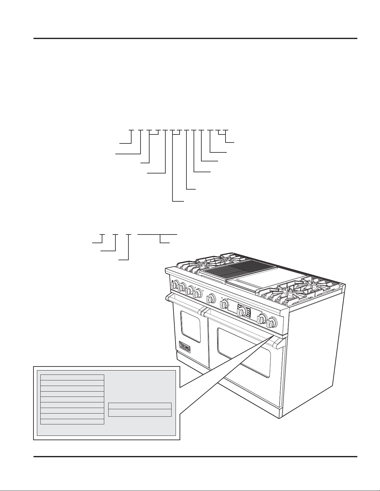
V D SC548T4GQSS
Model – Serial Number Matrix
The serial number and model number for your
appliance are located on the identification plate
mounted on the underside of the control panel.
Model Numbers
V=Viking Professional Series
Dual Fuel
Self Clean
Serial Numbers
03 03 09 R00002015
Month
Day
Year of Manufacture
Version
SS=Stainless
Grill
Griddle
4 burner
6 burner
Electronic Touch Control
30” Wide
36” Wide
48” Wide
Serial Number
GAZ DU HAUT
BTU (KW) HR RATE NATURAL
SURFACE 1@ 15,000 (4.4) 12,500 (3.7)
SURFACE 1@ 18,500 (4.4) 16,000 (4.8)
FOUR ELECTRIUE
VOLTS Hz WATTS AMPS
240V/120VAC 60 5800 24
208V/120VAC 60 4200 20.8
005186-000
LP/PROPANE
VIKING RANGE CORP.
GREENWOOD, MISSISSIPPI 38930
MODEL/
MODELE
NUMBER/
NUMERO
© 2011 Viking Preferred Service
MADE IN USA
VDSC548T4GQSS
070109C00022890
16
16
Operation
Settings and Functions
Lighting Burners
All burners are ignited by electric
ignition. There are no openflame, “standing” pilots.
Surface Burners-Automatic
Reignition
To light the surface burners, push and turn the
appropriate control knob counterclockwise to any
position. This control is both a gas valve and an
electric switch. Burners will ignite at any “ON” position with the automatic re-ignition system. If the
flame goes out for any reason, the burners will automatically re-ignite if the gas is still flowing. When
gas is permitted to flow to the burners, the electric
igniters start sparking. On all surface igniters you
should hear a “clicking” sound. If you do not, turn
off the control and check that the unit is plugged in
and that the fuse or circuit breaker is not blown or
tripped.
Within a few moments, enough gas will have
traveled to the burner to light. When the burner
lights, turn the burner control to any position to
adjust the flame size. Setting the proper flame
height for the desired cooking process and
selecting the correct cooking vessel will result in
superior cooking performance, while also saving
time and energy.
Griddle
(VDSC536T-4G, VDSC548-4GQ, VDSC548-6G)
The optional 15,000 BTU griddle is constructed
of machined steel with a blanchard finish and
is uniquely designed to offer excellent cooking
performance as well as easy cleanup. The griddle is
equipped with an electronic thermostat to maintain
an even temperature across the griddle once the
desired temperature has been set. The griddle has
a power “ON” indicator light which glows when
the griddle thermostat has been turned on. This
will cycle on and off as needed to indicate the
thermostat is maintaining the selected temperature.
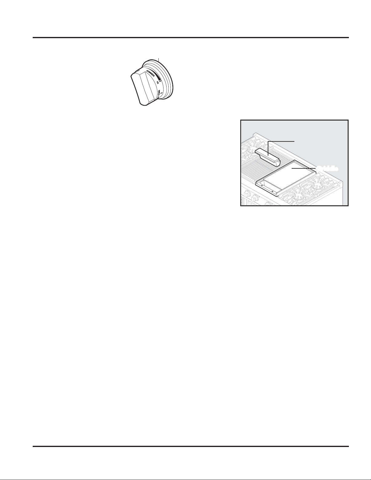
Griddle Operation
UÊ Ê/ÕÀÊÌiÊ}À``iÊVÌÀÊLÊ
counterclockwise to the desired temperature
setting. The power “ON” indicator light will
glow indicating the griddle thermostat is on.
UÊÊ Ê7iÊÌiÊ}À``iÊ>ÃÊÀi>Vi`ÊÌiÊ`iÃÀi`Ê
temperature, the power “ON” indicator light
will turn off indicating the griddle is preheated
to the selected temperature.
UÊÊ Ê1ÃiʵÕ`ÊV}ÊÊÀÊLÕÌÌiÀÊvÀÊi}}Ã]Ê
pancakes, French toast, fish, and sandwiches to
prevent sticking.
UÊÊ Ê,ÕÌiÞÊ
scrape
loose food
particles
with a metal
spatula
during
cooking to
make the
cleanup
easier and
to avoid the
particles
mixing with
the food.
UÊÊ Ê/ÊÌÕÀÊÌiÊ}À``iÊvv]ÊÌÕÀÊÌiÊÌiÀÃÌ>ÌÊ
knob clockwise to the “OFF” position.
UÊÊ ALWAYS turn to the“OFF” position when not in
use and lower the heat between cooking loads.
Char-Grill
(VDSC536T-4Q, VDSC548-4GQ, VDSC548-6Q)
The optional 18,000 BTU char-grill is equipped with
a single piece, heavy-duty porcelainized cast-iron
grill grate for easy movement of grilling items.
Beneath the grill grate is a slotted porcelainized
flavor-generator plate which is designed to catch
drippings and circulate a smoke flavor back into
the food. Beneath the flavor-generator plate is a
two-piece drip pan which catches any drippings
that might pass beyond the flavor-generator plate.
This unique grilling system is designed to provide
outdoor-quality grilling indoors.
Char-Grill Operation
UÊÊ Ê/ÕÀÊÌiÊÛiÀi>`ÊÛiÌ>ÌÊÊ«ÀÀÊÌÊ
turning the grill on.
UÊÊ /ÕÀÊÌiÊ}ÀÊLÊVÕÌiÀVVÜÃiÊÌÊ°Ê
UÊÊ ÊÜ>ÞÃÊ«Àii>ÌÊÌiÊ}ÀÊvÀÊx£äÊÕÌiÃÊ
before placing food on the grill grate.
UÊÊ *>ViÊv`ÊÌiÃÊÊÌiÊ}À]ÊVÊ>ÃÊ`iÃÀi`°
UÊÊ Ê/ÊÌÕÀÊÌiÊ}ÀÊvv]ÊÌÕÀÊÌiÊ}ÀÊLÊ
clockwise to the “OFF” position.
Griddle Assembly
Grease trough
Griddle
Griddle
© 2011 Viking Preferred Service
17
Operation
Settings and Functions–30" Oven
Control Operation–Electronic Control
The following is the basic layout of the buttons, displays and how they are referenced below.
Control /Selector Knob
Left Display
Time and Probe Functions
8 Program Buttons
(Oven and Time Functions)
The main Controller governs all oven operations as
well as timing and meat probe functions.
There are two digital displays, one on each side of
the control knob and program buttons.
Left Display Window
The left display windows
indicates the following:
Ê UÊ/iÊvÊ>Þ
Ê UÊ-Ì«Ê/i
Ê UÊÊ/iÊ
Ê UÊÊÕÌiÊÌiÀ
countdown
Clock, Time Function and Temp Probe Display
When AC power is applied (including after a power
loss), the CLOCK display defaults to a flashing
“12:00” and the word SET is displayed above the
flashing display and begins the incremental time.
Set the time as shown on page 19. When in any
TIME programming mode, if a display indictor is
flashing, pressing the “CLEAR/ SETTINGS” button
will cancel the program and revert the display to
the default setting (TIME OF DAY). Once a program
has started, the CLEAR function is deactivated and
the “OFF” button must be depressed to cancel a
timed program.
Once set, the current time will be displayed.
Depressing the “OFF” button will extinguish
the display. Though the display is OFF, the clock
function is operating.
© 2011 Viking Preferred Service
(Oven and Temperature Functions)
Right Display
Display Time of Day
If the display is off, depressing the “OVEN FUNC”,
“OVEN TEMP”, “OFF” or “CLEAR/SETTINGS”
buttons will activate the display and show the current
time of day. Depressing the “CLOCK/PROBE” button
will activate the display and allow adjustments to the
current time of day.
Depressing the “MIN/SEC TIMER”, “COOK
TIME”, and “STOP TIME” buttons will activate the
display and allow time function programming. If
you depress the “OFF” button once while in any
of these modes, the TIME OF DAY will display.
Depressing a second time will extinguish the display.
Right Display Window
The right display window
indicates the following:
Ê UÊÊ}Ê`iÊ-iiVÌ
Ê UÊ*Àii>ÌÊ/i«iÀ>ÌÕÀi
Ê UÊ-iiVÌi`Ê/i«iÀ>ÌÕÀi
Temperature And Oven Function
Temperature settings range from 150°F (55.5°C) –
550°F (287.8°C). Each increase/decrease is in 5ºF
(2ºC) increments.
Temperature Display
Actual Temp (PREHEAT only): 1ºF (1ºC) increments
Meat Probe Actual Temp: 1ºF (1ºC) increments
Set Temp (all other cycles): 5ºF (2ºC) increments
Note: PREHEAT and Meat Probe are the only cycles
where actual temperature is displayed. Otherwise
display shows only set temperature.
18
Operation
Settings and Functions–30” Oven
Clock/Probe
Setting Time of Day
(Clock defaults to
“12:00” and flashes
when first powered up or
CLOCK/
PROBE
MIN/SEC
TIMER
COOK
TIME
STOP
TIME
OVEN
FUNC
OVEN
TEMP
OFF
CLEAR/
SETTINGS
if power is interrupted.)
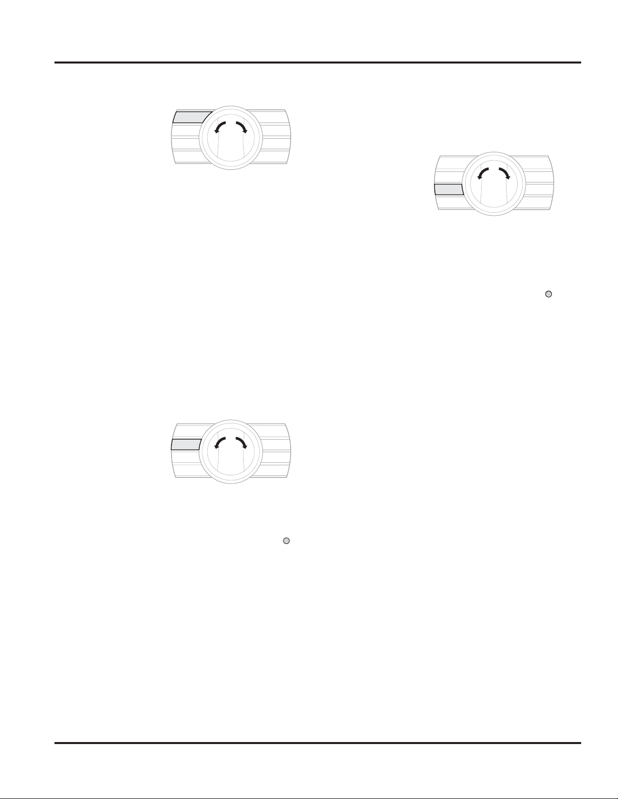
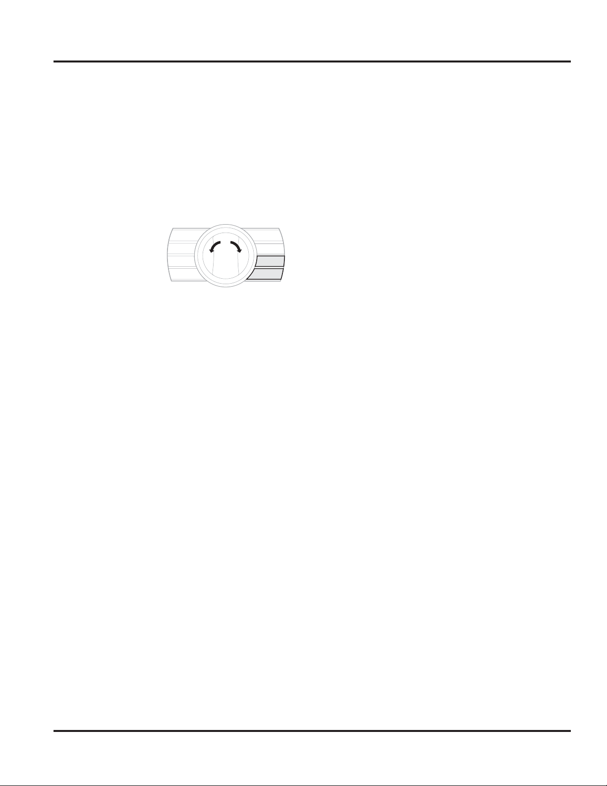
1. Press “CLOCK/PROBE” button. The clock
display will flash.
2. Toggle ”SELECTOR KNOB” right to increase or
left to decrease to set desired time. Time will
scroll in one minute increments per individual
toggle. If “SELECTOR KNOB” is held in either
right or left position, time will increase or
decrease in 10 minute increments until desired
time is reached. Clock automatically rolls from
AM to PM.
3.
Push in
”SELECTOR KNOB”
to accept time and
start timer or after five seconds, time will autoaccept
.
When clock is set and needs to be changed, press
”CLOCK/PROBE” button and follow the two steps
above. Clock display will flash when activated.
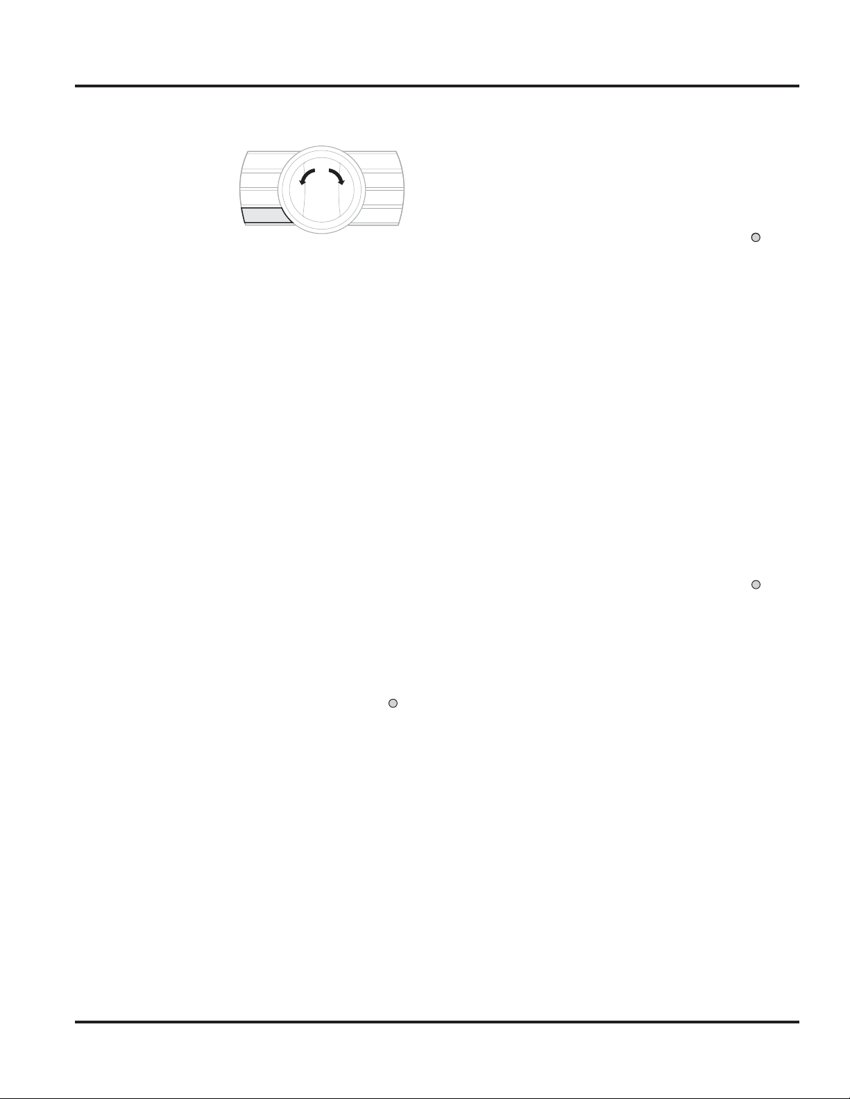
Min/Sec Timer
(Used to operate timer
independently from
oven.)
1. Press ”MIN/SEC
CLOCK/
PROBE
MIN/SEC
TIMER
COOK
TIME
STOP
TIME
OVEN
FUNC
OVEN
TEMP
OFF
CLEAR/
SETTINGS
TIMER” button.(0:00
will flash in display along
with HR and MIN). Hours
are to the left of the colon
Clock Display
SET
HR MIN
and minutes are to the
right. TIMER will illuminate
under display.
00:00
STOP TIMER NO PROBE
COOK TIME ON DELAY
AM
PM
2. Toggle ”SELECTOR
KNOB” right to increase or left to decrease
to set the desired time. Time will scroll in one
minute increments per individual toggle. If
”SELECTOR KNOB” is held in either right or
left position, time will increase or decrease in 10
minute increments until desired time is reached.
3. Push in ”SELECTOR KNOB” to accept time or
after five seconds, stop time will auto-accept.
Time will count down on display from programmed
time. There will be an audible beep at one minute
and three beeps when time expires (0:00).
Cook Time
(Start cooking now.)
The total cooking
duration can be set
to automatically shut
CLOCK/
PROBE
MIN/SEC
TIMER
COOK
TIME
STOP
TIME
OVEN
FUNC
OVEN
TEMP
OFF
CLEAR/
SETTINGS
the oven off at the
desired time.
1. Press ”COOK TIME” button. (0:00 will flash in
display along with HR
and MIN). Hours are to
the left of the colon and
Clock Display
SET
HR MIN
minutes are to the right.
COOK TIME will
illuminate under display.
00:00
STOP TIMER NO PROBE
COOK TIME ON DELAY
AM
PM
2. Toggle ”SELECTOR
KNOB” right to increase or left to decrease to
set desired time. Time will scroll in one minute
increments per individual toggle. If ”SELECTOR
KNOB” is held in either right or left position,
time will increase or decrease in 10 minute
increments until desired time is reached.
3. Push in ”SELECTOR KNOB” to accept time or
after five seconds, time will auto-accept.
4. Set OVEN FUNCTION and OVEN
TEMPERATURE as detailed in “Set Oven
Function and Temperature” on
pages 21-23.
Timer will activate and count down once OVEN
FUNCTION and OVEN TEMPERATURE have been
activated. There will be an audible beep at one
minute and three long beeps when time expires
(0:00). Pressing the “COOK TIME” button, then
the ”CLEAR/SETTINGS” button will deactivate
the timer during any cook program. The oven
will continue to function normally. Depressing the
“OFF” button during a timed cook cycle will shut
timer and oven off.
Note: Cook timer does not count down during
PREHEAT mode.
© 2011 Viking Preferred Service
19
Operation
Settings and Functions–30” Oven
Stop Time
(Used in conjunction
with COOK TIME.)
When your cooking
needs require a specific
CLOCK/
PROBE
MIN/SEC
TIMER
COOK
TIME
STOP
TIME
OVEN
FUNC
OVEN
TEMP
OFF
CLEAR/
SETTINGS
start and finish cook
time, you would use this function along with COOK
TIME. You will first set the time you want the recipe
to finish, then select the length of cook time. The
EOC calculates the required start time (plus
25 minutes for preheat).
For example:
Let’s say you have a recipe that requires two hours
of cooking at 350°F and you want the cooking
to finish at 6:00 PM. You would first press the
“STOP TIME” button and using the SELECTOR
KNOB, dial in 6:00 PM, then depress the
“SELECTOR KNOB”. The display will automatically
switch to the COOK TIME program. Next dial in
2:00 for two hours of cooking and depress the
“SELECTOR KNOB”. You have now dialed in a
cooking time of two hours and a finish time of
6:00 PM. Now, select a cooking program (Bake)
and temperature (350°F) (See page 37 for Oven
Operation). The right display will show the selected
cook program and temperature and the left display
will show STOP TIME - 2:00 – DELAY. The oven will
not start until the desired cook time + preheat time
is reached, in this case 3:35 PM.
To Set Delayed Start:
1. Press ”STOP TIME”
button. (Current time
will flash and STOP will
illuminate under display.)
Clock Display
SET
HR MIN
02:00
STOP TIMER NO PROBE
COOK TIME ON DELAY
AM
PM
3. Push in ”SELECTOR KNOB” to accept time or
after five seconds, stop
time will auto-accept.
Once accepted, the
illuminated STOP TIME
will go off and COOK
TIME will illuminate under
display. COOK TIME will
Clock Display
SET
HR MIN
00:00
STOP TIMER NO PROBE
COOK TIME ON DELAY
AM
PM
display ”0:00”.
4. Set COOK TIME as detailed in “Cook Time” on
page 19.
5. Set OVEN FUNCTION and TEMPERATURE
FUNCTION as detailed in ”Set Oven Function
and Temperature” on page 21-23.
Once OVEN FUNCTION and OVEN TEMPERATURE
have been selected and activated, their settings
will be displayed during delay and through the
cooking process. Timer will display programmed
bake time. Below displayed bake time, DELAY
will be illuminated. Pressing
”CLOCK/PROBE” button shows
time while maintaining delay
programming. There will be an
audible beep at one minute
and three long beeps when
time expires (0:00). Pressing the
Clock Display
SET
HR MIN
02:00
STOP TIMER NO PROBE
COOK TIME ON DELAY
AM
PM
”CLEAR/SETTINGS” button will
deactivate timer at any time.
2. Toggle ”SELECTOR KNOB” right to increase or
left to decrease to set desired time. Time will
scroll in one minute increments per individual
toggle. If ”SELECTOR KNOB” is held in either
right or left position, time will increase or
decrease in 10 minute increments until desired
time is reached.
© 2011 Viking Preferred Service
20
General Information
General Information
Settings and Functions–30” Oven
Meat Probe
Refer to the Use
and Care manual
for proper use and
placement of the
CLOCK/
PROBE
MIN/SEC
TIMER
COOK
TIME
STOP
TIME
OVEN
FUNC
OVEN
TEMP
OFF
CLEAR/
SETTINGS
temperature probe for
required results.
1. With the probe inserted in the oven cavity
socket, Press ”CLOCK/
PROBE” button to
activate. Right display
Clock Display
SET
HR MIN
will read Meat Probe
Set Point. PROBE will
illuminate under left
display.
02:00
STOP
TIMER NO PROBE
COOK TIME ON DELAY
AM
PM
2. Toggle ”SELECTOR KNOB” right to increase or
left to decrease to desired temperature in 1ºF
increments.
3. Push in “SELECTOR KNOB” to accept time or
after five seconds, probe time will auto-accept.
4. Set OVEN FUNCTION and TEMPERATURE
as detailed in ”Set Oven Function and
Temperature” on pages 21-23.
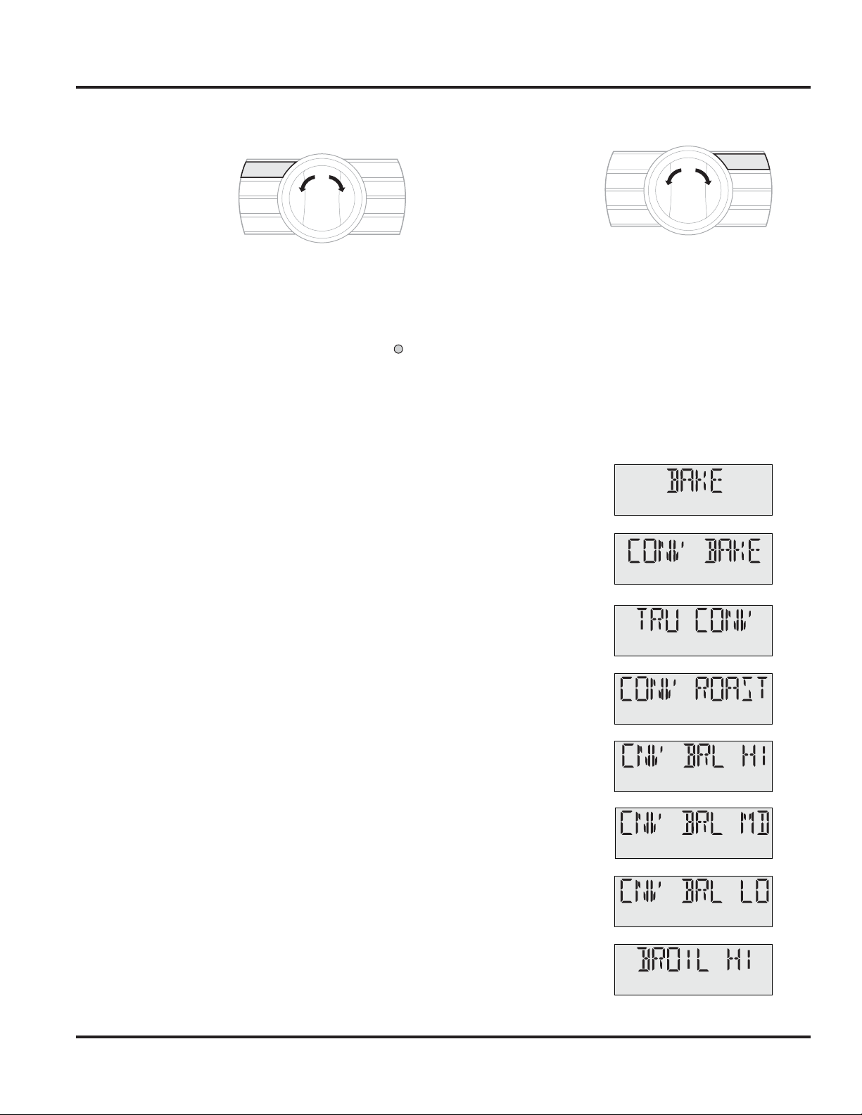
Set Oven Function:
1. Press ”OVEN
FUNCTION”
button. (BAKE is
set as default and
CLOCK/
PROBE
MIN/SEC
TIMER
COOK
TIME
STOP
TIME
OVEN
FUNC
OVEN
TEMP
OFF
CLEAR/
SETTINGS
flashes.)
2. Toggle ”SELECTOR KNOB” left or right to
desired oven function.
3. When desired oven function is flashing, push in
”SELECTOR KNOB” to accept and advance to
temperature settings. Exit with “OFF” button or
auto exit after five seconds with no SELECTOR
KNOB push.
Function Displays (General)
The functions look as follows:
BAKE
CONVECTION BAKE
Meat probe will display actual internal meat
temperature as it cooks. When programmed
Probe Temperature is achieved, there will be three
long beeps and right display alternates between
FUNCTION/Set Point and DONE/Meat Set Point.
On left display, PROBE icon flashes. Oven will
automatically turn off. The control emits a short
reminder beep every 60 seconds until the “OFF” or
“CLEAR/SETTINGS” button is pressed.
Note: DELAY COOK cannot be performed in
conjunction with a COOK BY PROBE operation as
DELAY COOK has no start time programmed in.
Note: TIMED COOK can be performed along with
a MEAT PROBE, but only when Meat Probe is used
for monitoring only.
TRUE CONVECTION
CONVECTION ROAST
CONVECTION BROIL
HI (fixed 550°F)
CONVECTION BROIL
MED (fixed 450°F)
CONVECTION BROIL
LO (fixed 350°F)
BROIL HIGH
(fixed 550°F)
© 2011 Viking Preferred Service
21
21
Operation
Settings and Functions–30” Oven
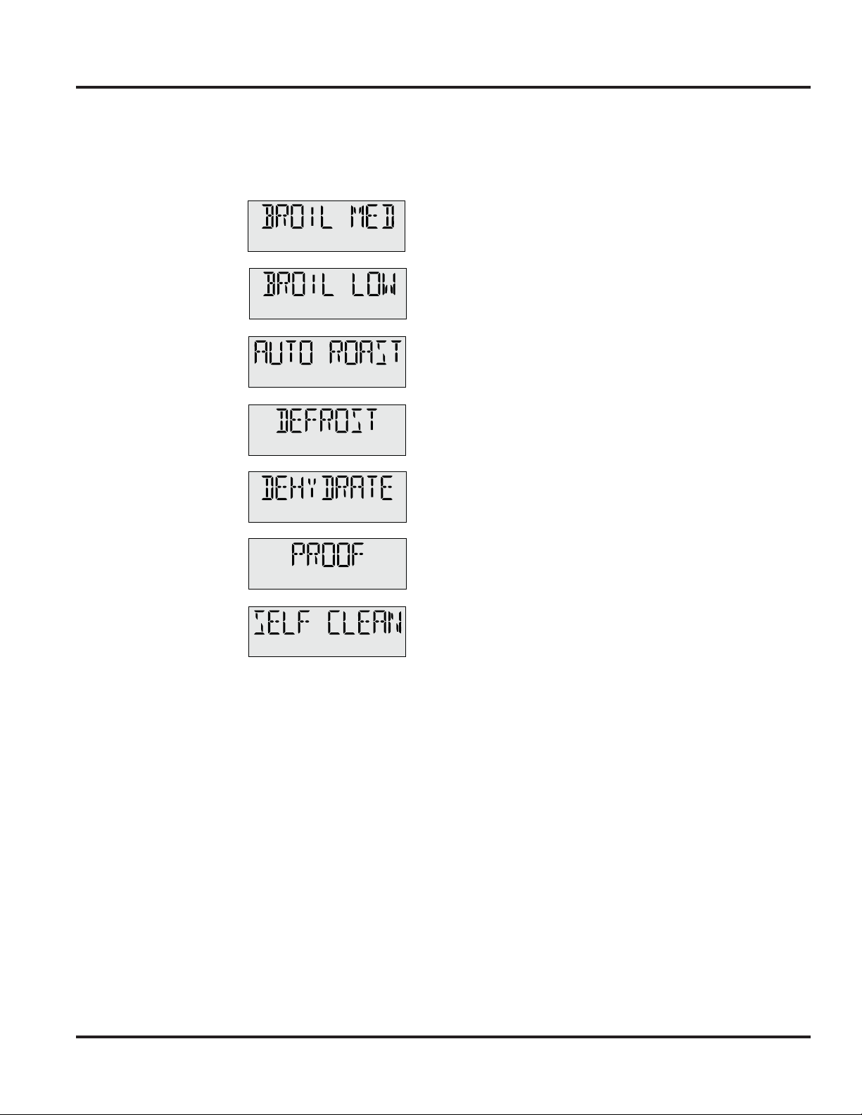
Function Displays (General) (cont.)
BROIL MEDIUM
(fixed 450°F)
BROIL LOW
(fixed 350°F)
AUTO ROAST
DEFROST
DEHYDRATE
PROOF
SELF CLEAN
Set Oven Temperature:
Once the oven function is selected, the function
display stops flashing and proceeds to temperature
setting.
1. When a temperature is flashing in the display
you can adjust up or down in increments of
5 or 25 degrees.
a. The default temperature for BAKE is 350ºF.
All Convection programs (except CONV
BROIL) and AUTO ROAST default to
325ºF. If the default temperature requires
adjustments, toggle to the left to decrease or
to the right to increase the temperature in
5º increments. If you hold in either direction,
the temperature will increase in 25º
increments until desired temperature
has been achieved.
b. For ALL broil programs, the temperatures are
fixed and cannot be adjusted.
c. DEHYDRATE and PROOF default to 90°F.
d. SELF CLEAN has no temperature adjustment.
2. When desired temperature is flashing, push
in ”SELECTOR KNOB” to accept desired
oven temperature and start timer or after five
seconds, temperature will auto accept (except
SELF CLEAN). Once oven temperature has
been selected, it ceases to flash.
© 2011 Viking Preferred Service
22

Operation
Settings and Functions–30” Oven
Set Oven Temperature (cont.):
3. Display will intermittently display both
set OVEN FUNCTION with set OVEN
TEMPERATURE and PREHEAT and actual
temperature until set temperature is reached at
which point the set OVEN FUNCTION and set
OVEN TEMPERATURE are locked in.
Oven will not be activated until both OVEN
FUNCTION and OVEN TEMPERATURE are set.
Oven temperature can be changed at any time by
pressing ”OVEN TEMPERATURE” and repeating
Steps 1 and 2 . Oven can be deactivated at any time
by pressing ”OFF”.
Note: OVEN TEMPERATURE button does not
need to be pushed as the program automatically
moves to setting OVEN TEMPERATURE after
OVEN FUNCTION is selected.
Note: If an oven function is not selected, control
exits to comply with two-step “ON” requirement.
Note: If no selection has been made in OVEN
TEMPERATURE, oven auto-starts at default
temperature.
Note: While preheating, display will alternate
between PREHEAT and FUNCTION and
TEMPERATURE selected.
Self-Clean
If Self-Clean is selected:
1. The control initiates the door lock. During this
period, the display shows LOCKING.
2. Once the door is locked, the control displays
SELF CLEAN and the time remaining on the
display.
3. The control continues in Self-Clean mode for
the required self-clean duration.
4. Once the Self-Clean cycle is complete, the
control displays COOL DOWN. The door
remains locked.
5. When 500ºF is reached, the control unlocks the
door and COOL DOWN is no longer displayed.
Note: The cooling fan will operate throughout the
complete 3.5 hour self-clean cycle, as well as the
cool down stage until the cavity temperature drops
below 250˚F temp.
Normal Operation
Once the FUNCTION and TEMPERATURE are set,
and PREHEAT completes, oven will beep indicating
set temperature has been reached and normal
operation begins.
1. The display shows set temperature.
Note: PREHEAT is the only cycle where actual
temperature is displayed, otherwise the display
shows set temperature.
Note: Certain functions include a PREHEAT cycle.
Once set temperature has been reached, the oven
will automatically exit PREHEAT and follow normal
operation mode.
© 2011 Viking Preferred Service
2. Oven temperature can be adjusted at any
time by pressing “OVEN TEMPERATURE”,
then rotating “SELECTOR KNOB”. Push in
“SELECTOR KNOB” to accept or auto-accept
after five seconds. If user wants to return to
previous setting, press the “CLEAR/SETTINGS”
button (as long as the SELECTOR KNOB has
not been pushed in).
3.
If oven is no longer at correct temperature due to
opening oven door, control will revert to PREHEAT.
23
Operation
Settings and Functions–30” Oven
Hold Mode
Automatically begins at end of TIMED COOK or
DELAY COOK.
1. Control sounds a short reminder beep, every
60 seconds and temperature is set at 150ºF.
2.
Display alternates between Function and Hold.
After two hours in HOLD mode, oven turns
“OFF”.
Sabbath Mode
This mode offers users
belonging to religions
with “no work”
restrictions to program
CLOCK/
PROBE
MIN/SEC
TIMER
COOK
TIME
STOP
TIME
OVEN
FUNC
OVEN
TEMP
OFF
CLEAR/
SETTINGS
their ovens to comply
with the Sabbath
requirement. When oven door is opened in Sabbath
mode, the oven light stays off while the convection
fan and heating elements remain on.
Showroom Mode
In Showroom mode, all operations of the oven
(heating elements, convection and cooling fans) are
disabled. The oven cavity lights will operate, as well
as the oven controls and display.
Control Lock
This feature allows user to lock out the control
panel to prevent adjustments to the user settings.
1. To activate, press ”OFF” and ”CLEAR/
SETTINGS” buttons simultaneously. You will
hear three beeps indicating that the sequence
was entered properly. Continue holding for five
seconds. There will be an audible beep and the
right display panel will show LOCKED and the
left display (CLOCK) will go out. Pressing any
of the 8 buttons or the “SELECTOR KNOB” will
sound a three tone signal and right display will
show LOCKED.
2. In order to deactivate, repeat the procedure
used to lock the door. When the sequence is
entered successfully, the word UNLOCKED will
display for three seconds, then extinguish while
the clock display comes on and displays the
time of day.
Note: Door lock will not work in conjunction with
this function.
© 2011 Viking Preferred Service
24
Operation
Settings and Functions–Cycle Charts
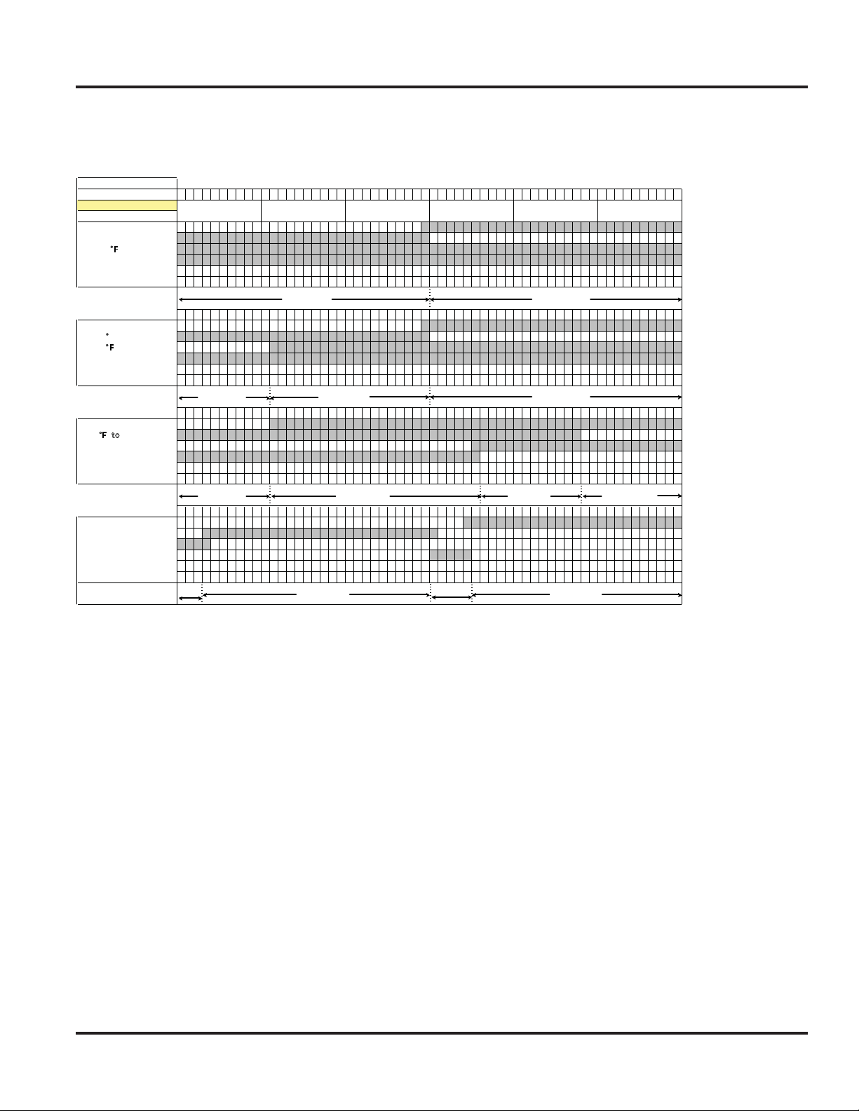
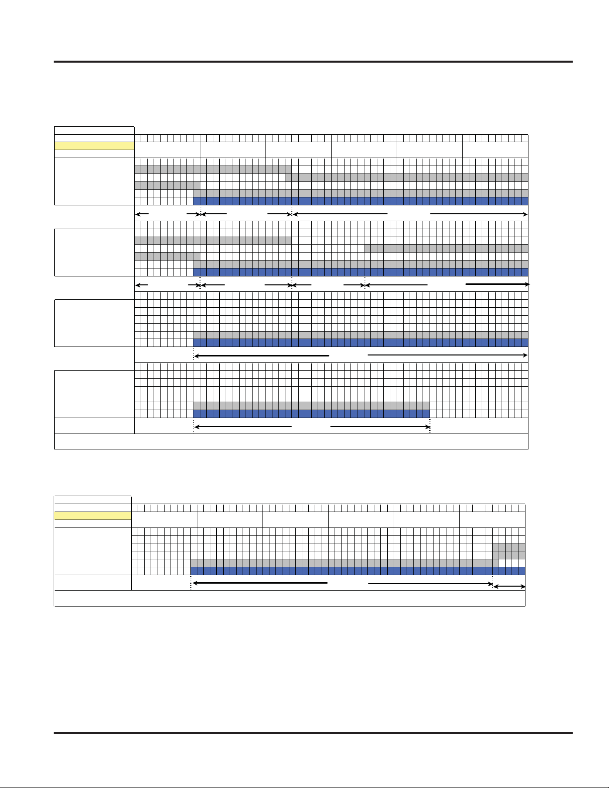
VDSC548T–Right Oven–Bake Cycle
VDSC548T - RH TIME (In Secs)
CYCLE: BAKE
PHASE ELEMENTS
Preheat 1 Inner Bake
Ambient Outer Bake
F
to 150 °
Preheat 2 Inner Bake
150 F °
250 °
Preheat 3 Inner Bake
250 °
Setpoint Inner Broil
Cook Inner Bake
F to
to
F
Inner Broil
Outer Broil
Convection
Conv Fan
Outer Bake
Inner Broil
Outer Broil
Convection
Conv Fan
Outer Bake
Outer Broil
Convection
Conv Fan
Outer Bake
Inner Broil
Outer Broil
Convection
Conv Fan
123456789101112131415161718192021222324252627282930313233343536373839404142434445464748495051525354555657585960
10 Seconds
123456789101112131415161718192021222324252627282930313233343536373839404142434445464748495051525354555657585960
13.7 amps
123456789101112131415161718192021222324252627282930313233343536373839404142434445464748495051525354555657585960
13.7 amps
123456789101112131415161718192021222324252627282930313233343536373839404142434445464748495051525354555657585960
8 7.2
20 Seconds 30 Seconds 40 Seconds 50 Seconds
21.7 amps 21.7 amps
21.7 amps 21.7 amps
20.2 amps
6.5 amps
60 Seconds
21 amps 14.5 amps
6.5 amps
© 2011 Viking Preferred Service
25
Operation
Settings and Functions–Cycle Charts
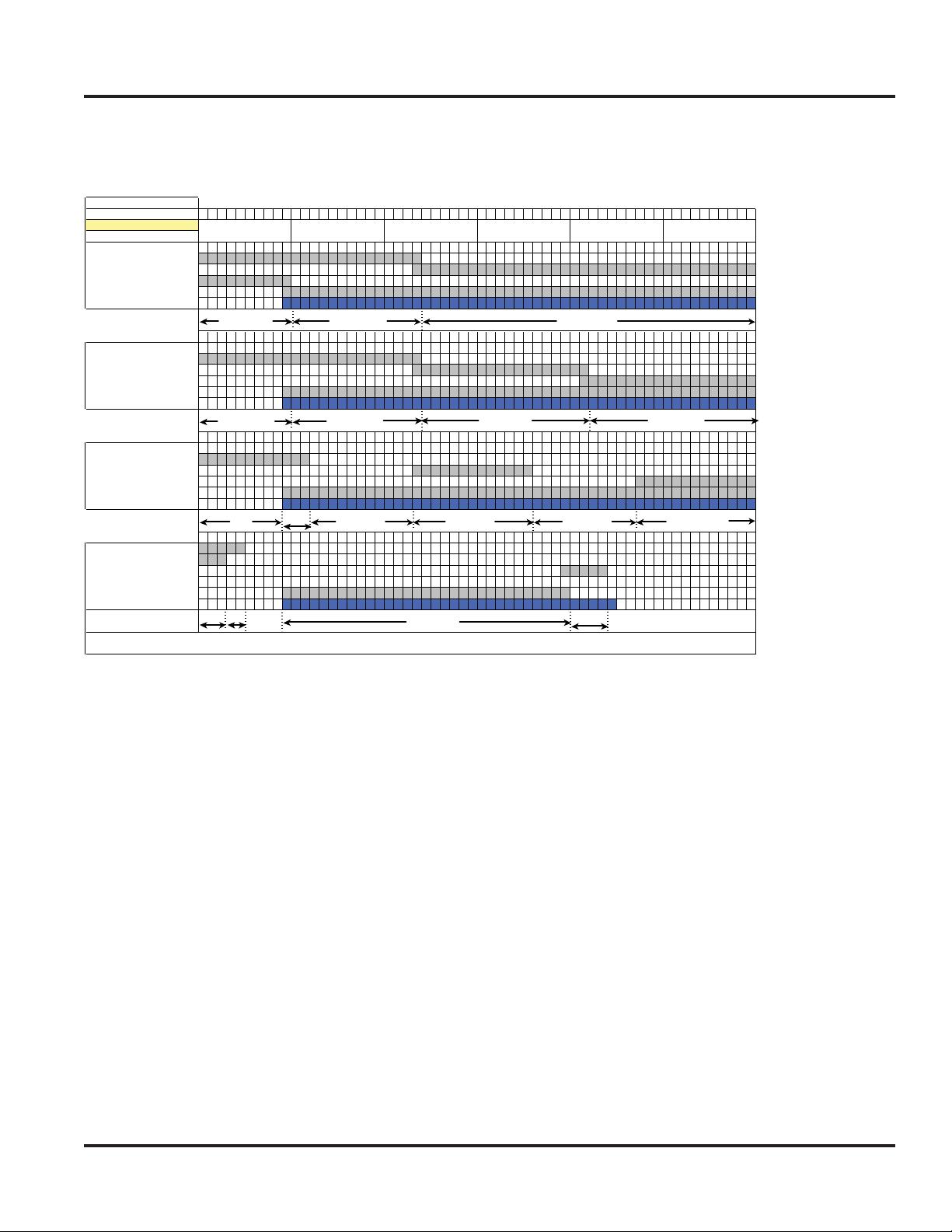
VDSC548T–Right Oven–Convection Bake Cycle
VDSC548T - RH TIME (In Secs)
CYCLE: CONV BAKE
PHASE
Preheat 1 Inner Bake
Ambient Outer Bake
to 150 °F Inner Broil
Preheat 2 Inner Bake
150 F ° to Outer Bake
250 °F Inner Broil
Preheat 3 Inner Bake
250 °F to Outer Bake
Setpoint Inner Broil
Cook Inner Bake
ELEMENTS
Outer Broil
Convection
Conv Fan
Outer Broil
Convection
Conv Fan
Outer Broil
Convection
Conv Fan
Outer Bake
Inner Broil
Outer Broil
Convection
Conv Fan
1 2 3 4 5 6 7 8 9 10 11 12 13 14 15 16 17 18 19 20 21 22 23 24 25 26 27 28 29 30 31 32 33 34 35 36 37 38 39 40 41 42 43 44 45 46 47 48 49 50 51 52 53 54 55 56 57 58 59 60
10 Seconds
13.7 amps
1 2 3 4 5 6 7 8 9 10 11 12 13 14 15 16 17 18 19 20 21 22 23 24 25 26 27 28 29 30 31 32 33 34 35 36 37 38 39 40 41 42 43 44 45 46 47 48 49 50 51 52 53 54 55 56 57 58 59 60
6.5 amps
1 2 3 4 5 6 7 8 9 10 11 12 13 14 15 16 17 18 19 20 21 22 23 24 25 26 27 28 29 30 31 32 33 34 35 36 37 38 39 40 41 42 43 44 45 46 47 48 49 50 51 52 53 54 55 56 57 58 59 60
6.5
1 2 3 4 5 6 7 8 9 10 11 12 13 14 15 16 17 18 19 20 21 22 23 24 25 26 27 28 29 30 31 32 33 34 35 36 37 38 39 40 41 42 43 44 45 46 47 48 49 50 51 52 53 54 55 56 57 58 59 60
13 6.5
NOTE: Convection fan is running at LOW speed. Motor changes direction
20 Seconds 30 Seconds 40 Seconds 50 Seconds
17.5 amps 19 amps
17.5 amps
17.5
11 amps
19 amps
11 amps
60 Seconds
19 amps 18.2 amps
11 amps 18.2 amps
8
© 2011 Viking Preferred Service
26
Operation
Settings and Functions–Cycle Charts
VDSC548T–Right Oven–Tru Convection Cycle
VDSC548T - RH TIME (In Secs)
CYCLE: TRU CONV
PHASE ELEMENTS
Preheat 1 Inner Bake
Ambient Outer Bake
to 150 °F Inner Broil
Preheat 2 Inner Bake
150 F ° to Outer Bake
250 °F Inner Broil
Preheat 3 Inner Bake
250 °F to Outer Bake
Setpoint Inner Broil
Cook Inner Bake
Outer Broil
Convection
Conv Fan
Outer Broil
Convection
Conv Fan
Outer Broil
Convection
Conv Fan
Outer Bake
Inner Broil
Outer Broil
Convection
Conv Fan
1 2 3 4 5 6 7 8 9 101112131415161718192021222324252627282930313233343536373839404142434445464748495051525354555657585960
10 Seconds
13.7 amps
1 2 3 4 5 6 7 8 9 101112131415161718192021222324252627282930313233343536373839404142434445464748495051525354555657585960
13.7 amps
1 2 3 4 5 6 7 8 9 101112131415161718192021222324252627282930313233343536373839404142434445464748495051525354555657585960
1 2 3 4 5 6 7 8 9 101112131415161718192021222324252627282930313233343536373839404142434445464748495051525354555657585960
20 Seconds 30 Seconds 40 Seconds 50 Seconds
17.5 amps 19 amps
17.5 amps
11 amps
11 amps
NOTE: Convection fan is running at LOW speed. Motor changes direction.
60 Seconds
19 amps
11 amps
VDSC548T–Right Oven–Convection Roast Cycle
VDSC548T - RH
CYCLE: Conv Roast
PHASE
Preheat 1 Inner Bake
Preheat 2 Outer Bake
Preheat 3 Inner Broil
Cook Outer Broil
ELEMENTS
Convection
Conv Fan
123456789101112131415161718192021222324252627282930313233343536373839404142434445464748495051525354555657585960
10 Seconds
20 Seconds 30 Seconds 40 Seconds 50 Seconds
NOTE: Convection fan is running at HIGH speed. Motor changes direction.
© 2011 Viking Preferred Service
TIME (In Secs)
11 amps
60 Seconds
15.2
27
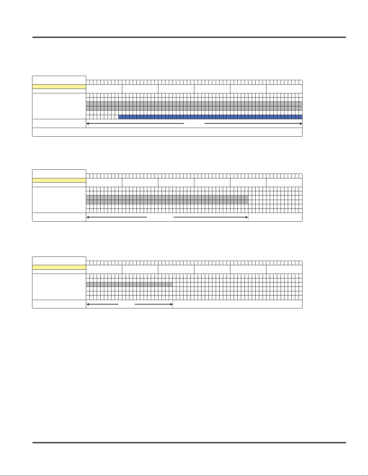
Operation
Settings and Functions–Cycle Charts
VDSC548T–Right Oven–Convection Broil Max Cycle
VDSC548T - RH TIME (In Secs)
123456789101112131415161718192021222324252627282930313233343536373839404142434445464748495051525354555657585960
CYCLE: Conv Broil MAX
PHASE ELEMENTS
Inner Bake
Outer Bake
Inner Broil
Outer Broil
Convection
Conv Fan
VDSC548T–Right Oven–Convection Broil Medium Cycle
10 Seconds 20 Seconds 30 Seconds 40 Seconds
15.2 amps
NOTE: Convection fan is running at HIGH speed. Motor changes direction.
50 Seconds 60 Seconds
VDSC548T - RH TIME (In Secs)
CYCLE: MED Broil
PHASE
ELEMENTS
Inner Bake
Outer Bake
Inner Broil
Outer Broil
Convection
Conv Fan
123456789101112131415161718192021222324252627282930313233343536373839404142434445464748495051525354555657585960
10 Seconds 20 Seconds 30 Seconds 40 Seconds
15.2 amps
VDSC548T–Right Oven–Convection Broil Low Cycle
VDSC548T - RH TIME (In Secs)
CYCLE: LOW Broil
PHASE ELEMENTS
Inner Bake
Outer Bake
Inner Broil
Outer Broil
Convection
Conv Fan
123456789101112131415161718192021222324252627282930313233343536373839404142434445464748495051525354555657585960
10 Seconds 20 Seconds 30 Seconds 40 Seconds
8 amps
50 Seconds 60 Seconds
50 Seconds 60 Seconds
© 2011 Viking Preferred Service
28
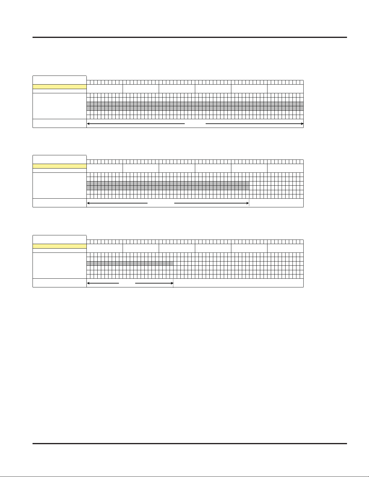
Operation
Settings and Functions–Cycle Charts
VDSC548T–Right Oven–High Broil Cycle
VDSC548T - RH TIME (In Secs)
123456789101112131415161718192021222324252627282930313233343536373839404142434445464748495051525354555657585960
CYCLE: HIGH Broil
PHASE
ELEMENTS
Inner Bake
Outer Bake
Inner Broil
Outer Broil
Convection
Conv Fan
VDSC548T–Right Oven–Medium Broil Cycle
10 Seconds 20 Seconds 30 Seconds 40 Seconds
15.2 amps
50 Seconds 60 Seconds
VDSC548T - RH TIME (In Secs)
CYCLE: MED Broil
PHASE ELEMENTS
Inner Bake
Outer Bake
Inner Broil
Outer Broil
Convection
Conv Fan
123456789101112131415161718192021222324252627282930313233343536373839404142434445464748495051525354555657585960
10 Seconds 20 Seconds 30 Seconds 40 Seconds
15.2 amps
VDSC548T–Right Oven–Low Broil Cycle
VDSC548T - RH TIME (In Secs)
CYCLE: LOW Broil
PHASE ELEMENTS
Inner Bake
Outer Bake
Inner Broil
Outer Broil
Convection
Conv Fan
123456789101112131415161718192021222324252627282930313233343536373839404142434445464748495051525354555657585960
10 Seconds 20 Seconds 30 Seconds 40 Seconds
8 amps
50 Seconds 60 Seconds
50 Seconds 60 Seconds
© 2011 Viking Preferred Service
29
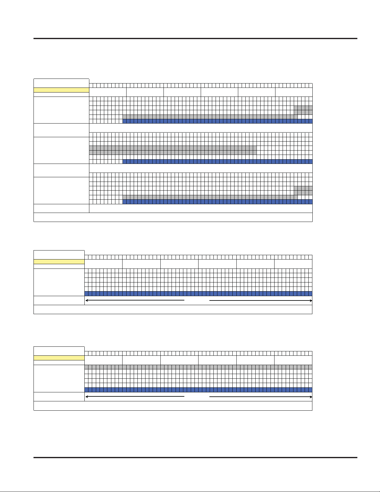
Operation
Settings and Functions–Cycle Charts
VDSC548T–Right Oven–Auto Roast Cycle
VDSC548T - RH TIME (In Secs)
CYCLE: Auto Roast
PHASE
Preheat 1 Inner Bake
Preheat 2 Outer Bake
Preheat 3 Inner Broil
123456789101112131415161718192021222324252627282930313233343536373839404142434445464748495051525354555657585960
Searing Inner Bake
123456789101112131415161718192021222324252627282930313233343536373839404142434445464748495051525354555657585960
Cook Inner Bake
ELEMENTS
Outer Broil
Convection
Conv Fan
Outer Bake
Inner Broil
Outer Broil
Convection
Conv Fan
Outer Bake
Inner Broil
Outer Broil
Convection
Conv Fan
123456789101112131415161718192021222324252627282930313233343536373839404142434445464748495051525354555657585960
10 Seconds 20 Seconds 30 Seconds 40 Seconds
11 amps
15.2 amps
11 amps
NOTE: Convection fan is running at HIGH speed. Motor changes direction.
50 Seconds 60 Seconds
VDSC548T–Right Oven–Defrost Cycle
VDSC548T - RH TIME (In Secs)
CYCLE: DEFROST
PHASE
ELEMENTS
Inner Bake
Outer Bake
Inner Broil
Outer Broil
Convection
Conv Fan
1 2 3 4 5 6 7 8 9 101112131415161718192021222324252627282930313233343536373839404142434445464748495051525354555657585960
10 Seconds 20 Seconds 30 Seconds 40 Seconds
6.5 Amps
NOTE: Convection fan is running at Low speed. Motor changes direction.
NO HEATING ELEMENTS UTILIZED
50 Seconds 60 Seconds
15.2
15.2
VDSC548T–Right Oven–Dehydrate Cycle
VDSC548T - RH TIME (In Secs)
CYCLE: DEHYDRATE
PHASE
90°
ELEMENTS
Inner Bake
Outer Bake
Inner Broil
Outer Broil
Convection
Conv Fan
1 2 3 4 5 6 7 8 9 101112131415161718192021222324252627282930313233343536373839404142434445464748495051525354555657585960
10 Seconds 20 Seconds 30 Seconds 40 Seconds
6.5 Amps
NOTE: Convection fan is running at Low speed. Motor changes direction.
© 2011 Viking Preferred Service
50 Seconds 60 Seconds
30
 Loading...