

Viking VDR7364GARLP Installation Manual

Installation Guide
Rear Trim/Curb Base Accessories
7 Series Ranges/Rangetops
Rear Trim Accessories
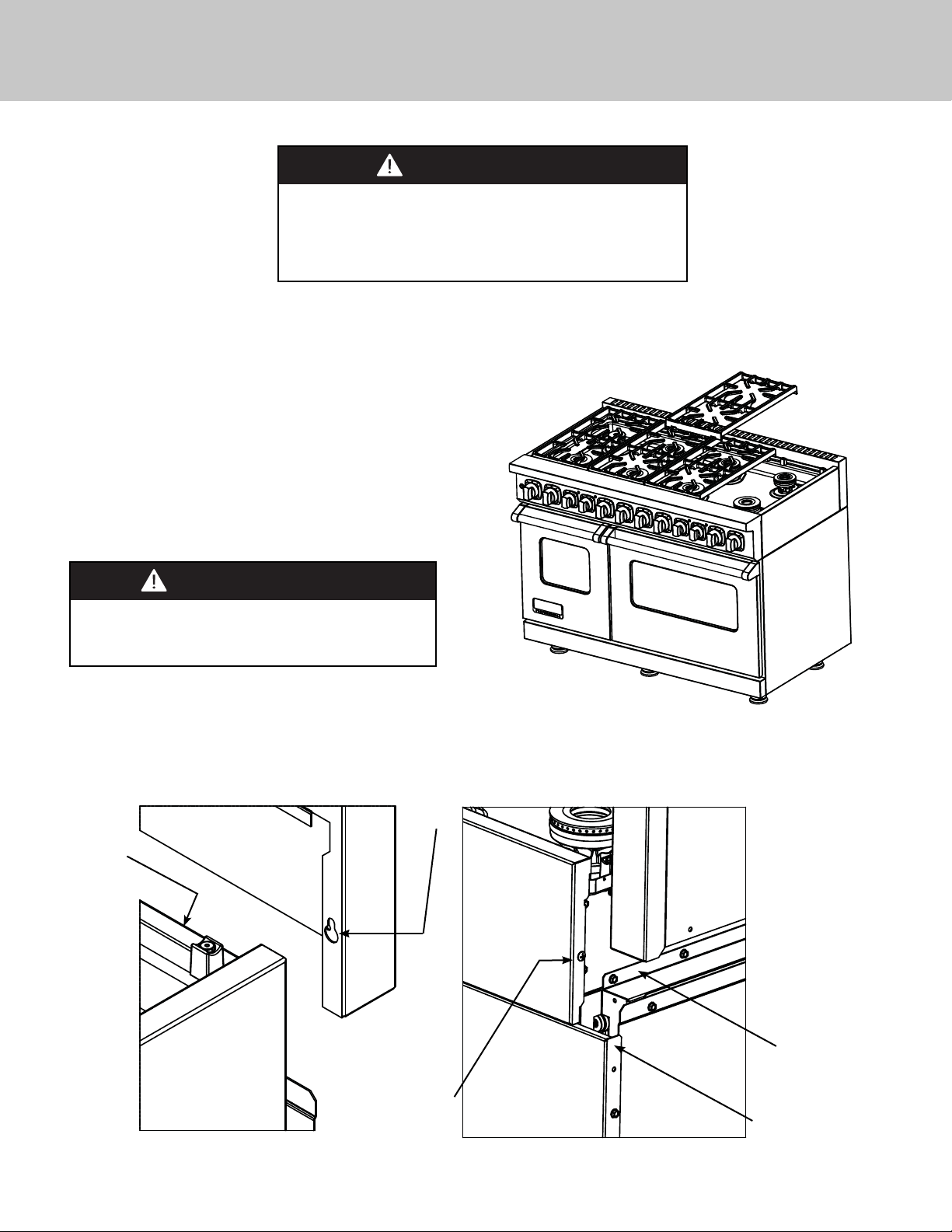
WARNING
To reduce the risk of fi re or injury to persons, check to
make sure all packaging has been removed from the
outside and inside parts of the rear trim device before
installing. MAKE SURE ALL CORRUGATED MATERIAL IS
REMOVED FROM INSIDE THE HIGH SHELF.
ATTACHING REAR TRIM
(Island Trim, 10” H. Backguard OR 24” H. High Shelf Back Panel)
1. Remove the grate supports in order to locate the rear fl ange
and mounting stud on the unit. Grasp the rear trim on each end
and carefully align the rear trim over the rear fl ange and insert
mounting screw into keyhole opening on the rear trim.
Make sure the rear trim is in front of the sealed burner
box and not behind.
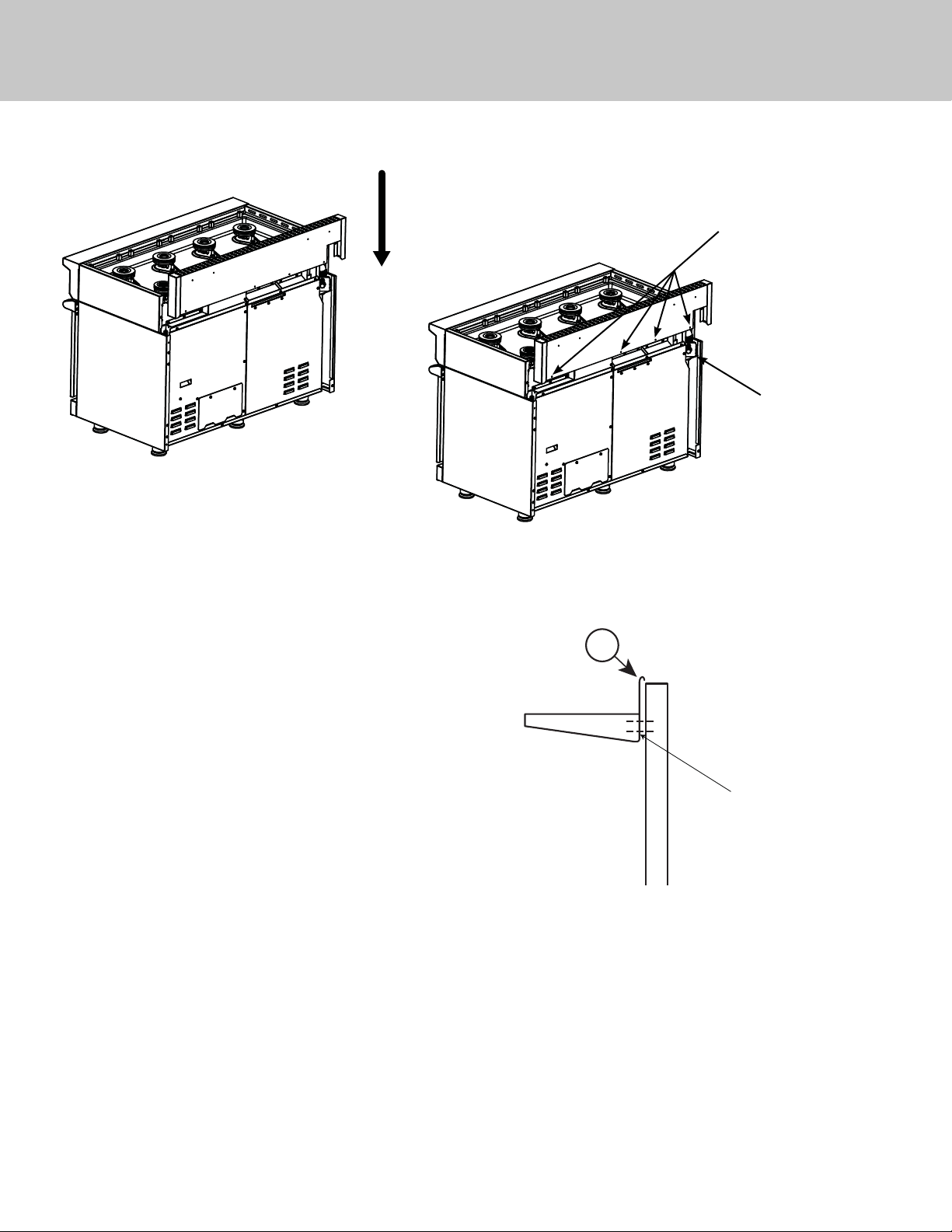
2. Align holes in rear trim with holes in fl ange. Slide
rear trim down until it rest on top of the side panels
ensuring accessory rear wall is outside of unit. Secure
with enclosed #10 x 1/2” (1.3 cm) phillips head
threaded screws. 36” W. ranges/rangetops have (3)
hole locations and 48” W ranges/rangetops have (4).
Remove
grates
CAUTION
To reduce the risk of injury, assistance from a
second person is recommended when installing
48” backguards or high shelf backs.
SIDE VIEW
Rear fl ange
REAR VIEW
Keyhole
opening
Mounting
screw
Side Panel
2
Rear Trim Accessories
NOTE: Regulator will be visible after rear trim
accessory is installed.
Screw
Locations
Regulator
X
24” H. High Shelf
After installing the high shelf back panel on the range/
rangetop, place the top rolled edge on the shelf (X) over the
front lip of the high shelf back panel. Secure with the (4)
enclosed #10 -24x 1/2” (1.3 cm) PH machine screws
Screw locations
(two on each side underneath shelf)
IMPORTANT: USE OF ISLAND TRIM WITH AND WITHOUT 6” (15.2 CM) REAR CLEARANCE.
Normal installation for island trim on either a range or rangetop is in an island/peninsula or where there is a minimum
clearance of 6”(15.2 cm) to any type of wall at the rear of the unit. Ranges and rangetops with an island trim installation
can be installed at zero clearance to the rear wall as long as the wall is non-combustible. The responsibility for ensuring
that the rear wall is non-combustible and heat resistant lies with the individual owner and/or end user. Only in those
cases where the island trim is installed with 6” (15.2 cm) of minimum clearance to a rear wall, or when a truly noncombustible material is used, will the warranty apply. In no case will Viking Range, LLC accept responsibility for any
claims which may result from heat damage against a rear wall, including cosmetic damage. It is the total responsibility of
the owner/end user to ensure that the material utilized in such applications is not only non-combustible, but is also truly
heat-resistant.
3
 Loading...