

Viking VCCI4209, VCCI3609, VCCI4210, VCCI5408, VCCI5409 Installation Instructions Manual
...
1
INSTALLATION
INSTRUCTIONS
PROFESSIONAL SERIES
BUILT-IN CHIMNEY-STYLE HOODS
VIKING
111 FRONT STREET
GREENWOOD, MISSISSIPPI 38930 USA
(662) 455-1200
NNOOTTEE:: IIFF IINNSSTTAALLLLIINNGG HHOOOODD WWIITTHH WWAARRMMIINNGG SSHHEELLFF PPAANNEELL,, IINNSSTTAALLLL WWAARRMMIINNGG SSHHEELLFF PPAANNEELL FFIIRRSSTT..
IIMMPPOORRTTAANNTT -- PPLLEEAASSEE RREEAADD AANNDD FFOOLLLLOOWW
•Before beginning, please read these instructions completely and carefully.
•Do not remove permanently affixed labels, warnings, or plates from the product. This may void the warranty.
•Please observe all local and national codes and ordinances. If no local codes are applicable, wire in accordance with the National
Electrical Code, ANSI/NFPA 70-latest edition.
•Check with a qualified and trained installer or local codes for makeup air requirement, if any.
•The installer should leave these instructions with the consumer who should retain for local inspector’s use and for future reference.
This hood is for residential installation only and is not designed for installation over a commercial product. Make sure power is off
at the main circuit breaker or fuse box before making connections. To avoid risk of fire, electric shock, or injury to persons, turn
off the electricity to the hood from the power supply before servicing or cleaning.
Viking hoods are equipped with variable speed controls for blowers. These units will not function with a single speed ventilator.
All Viking Range ventilator kits are designed specifically for use with Viking Range hoods. Use of any non-Viking Range ventilator
kit will void the hood warranty.
WARNING
TTOO RREEDDUUCCEE TTHHEE RRIISSKK OOFF FFIIRREE,, EELLEECCTTRRIICCAALL SSHHOOCCKK,, OORR IINNJJUURRYY TTOO PPEERRSSOONNSS,, OOBBSSEERRVVEE TTHHEE FFOOLLLLOOWWIINNGG::
1. Installation work and electrical wiring must be done by qualified person(s) in accordance with all applicable codes
and standards, including fire-rated construction.
2. Sufficient air is needed for proper combustion and exhausting of gases through the flue (chimney) of fuel burning
equipment to prevent back drafting. Follow the heating equipment manufacturer’s guideline and safety standards
such as those published by the National Fire Protection Association (NFPA), and the American Society for Heating,
Refrigeration and Air Conditioning Engineers (ASHRAE), and the local code authorities.
3. When cutting or drilling into wall or ceiling, do not damage electrical wiring and other hidden utilities.
4. Ducted fans must always be vented to the outdoors.
5.
WWAARRNNIINNGG
!: To reduce the risk of fire, use only metal ductwork.
6.
CCAAUUTTIIOONN
!: To reduce risk of fire and to properly exhaust air, be sure to duct air outside. Do not vent exhaust air
into spaces within walls or ceilings, or into attics, crawl spaces, or garages.
7.
CCAAUUTTIIOONN!!
: To Reduce the Risk of Fire and Electric Shock, Install this rangehood only with remote blower models
manufactured by Viking, model numbers - DEV900/DEV1200, VEV900/VEV1200, or DEV1500, VEV1500 or integral
blowers manufactured by Viking, model numbers - DIV300, DIV440, DIV600, DIV800, DIV1200, VIV300, VIV600, or
VIV1200.
NNOOTTEE
- Please refer inside for specific canopy/blower combinations.
CAUTION: For general ventilating use only. Do not use to exhaust hazardous or explosive materials and vapors.
WARNING
TO REDUCE THE RISK OF FIRE, ELECTRICAL SHOCK, OR INJURY TO PERSONS, RANGEHOODS MUST BE INSTALLED
WITH THE VENTILATORS THAT ARE SPECIFIED ON THEIR CARTON INDICATING SUITABILITY WITH THIS MODEL.
OTHER VENTILATORS CANNOT BE SUBSTITUTED.
WARNING
TTOO RREEDDUUCCEE TTHHEE RRIISSKK OOFF AA RRAANNGGEETTOOPP GGRREEAASSEE FFIIRREE::
1. Never leave surface units unattended at high setting. Boilovers cause smoking and greasy spillovers that may
ignite. Heat oils slowly on low or medium settings.
2. Always turn hood ON when cooking at high heat or when cooking flaming foods. (i.e. Crepes suzette, Cherries
jubilee, Peppercorn beef flambe).
3. Clean ventilating fans frequently. Grease should not be allowed to accumulate on fan or filter.
4. Use proper pan size. Always use cookware appropriate for the size of the surface element.
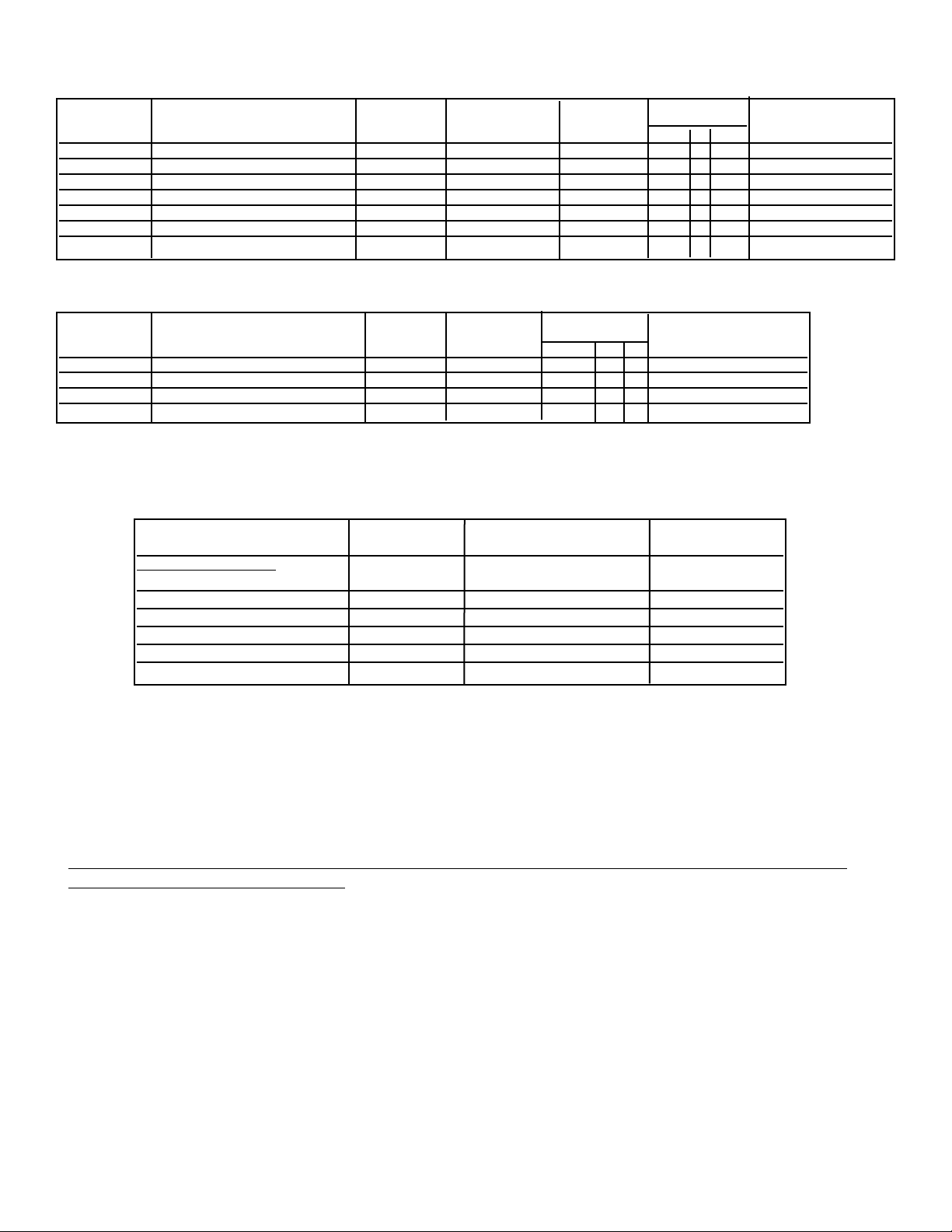
BBAASSIICC SSPPEECCIIFFIICCAATTIIOONNSS
IINNTTEERRIIOORR AANNDD EEXXTTEERRIIOORR PPOOWWEERR HHOOOODDSS
RREECCOOMM.. NNUUMMBBEERR OOFF 225500 WWAATTTT 112200VVAACC//6600HHzz
DDEESSCCRRIIPPTTIIOONN CCFFMM
11
HHAALLOOGGEENN HHEEAATT LLAAMMPPSS FFIILLTTEERRSS SSPPAACCEERRSS MMAAXX.. AAMMPPSS33
((iinntt..--iinntteerriioorr;; eexxtt..--eexxtteerriioorr)) LLIIGGHHTTSS ((SSoolldd SSeeppaarraatteellyy)) CCeenntteerr LLHH RRHH ((IInntteerriioorr//EExxtteerriioorr))
30” W. 300 int./600 int./900 ext./1200 ext. 2 1 2 0 1 1 3.9/6.0/8.7/6.0
36” W. * 300 int./600 int./900 ext./1200 ext. 2 1 2 1 1 1 3.9/6.0/8.7/6.0
42”W.* 600 int./900 ext./1200 ext. 2 1 2 1 1 1 6.0/8.7/6.1
48” W. 1200 int./1200 ext./1500 ext. 3 2 2 1 1 1 11.5/8.5/9.2
54” W. 1200 int./1200 ext./1500 ext. 3 2 3 2 1 1 11.5/8.5/9.2
60” W. 1200 int./1200 ext./1500 ext. 4 2 3 2 1 1 11.9/8.9/9.7
66” W. 1200 int./1200 ext./1500 ext. 4 2 3 0 1 1 11.9/8.9/9.7
RREECCOOMMMMEENNDDEEDD MMAAXX.. DDUUCCTT
MMOODDEELL NNUUMMBBEERR CCFFMM
11
DDUUCCTT SSIIZZEE RRUUNN22((fftt..))
FFoorr UUssee wwiitthh hhooooddss::
DIV300 (interior) 300 7” round 50
DIV600 (interior) 600 7” round 50
DIV1200 (interior) 1200 10” round 50
DEV900 (exterior) 900 10” round 50
DEV1200 (exterior) 1200 10” round 50
DEV1500 (exterior) 1500 10” round 75
PROPER INSTALLATION/DUCTING IS EXTREMELY IMPORTANT TO ENSURE MAXIMUM PERFORMANCE
FROM ANY VENTILATION PRODUCT
1. •All CFMs stated are based on tests at .1 static pressure: without applying static pressure, CFM would be greatly
overstated.
2. •Duct run length is for general reference only; for longer duct runs, increase duct size and contact a qualified and
trained installer.
•Straight runs and gradual turns are best; for example, each 90o elbow is equivalent to 5-10 feet (1.52 - 3.05 cm)
of straight run.
•Never use flexible duct; it creates back pressure/air turbulence and greatly reduces performance.
•Proper performance is dependent upon proper ducting; make sure that a qualified and trained installer is used.
•Check with a qualified and trained installer or local codes for makeup air requirement, if any.
3. •Max. amp rating for hoods includes recommended ventilator kit rating; all products must be hard wired direct
with 2-wire with ground.
**11220000 oorr 11550000 CCFFMM eexxtteerriioorr vveennttiillaattoorr sshhoouulldd bbee uusseedd wwhheenn iinnssttaalllleedd oovveerr rraannggeess//rraannggeettooppss wwiitthh ggaass ggrriillll..
RREECCOOMM.. NNUUMMBBEERR OOFF 112200VVAACC//6600HHzz
DDEESSCCRRIIPPTTIIOONN CCFFMM
11
HHAALLOOGGEENN FFIILLTTEERRSS SSPPAACCEERRSS MMAAXX.. AAMMPPSS33
((iinntt..--iinntteerriioorr;; eexxtt..--eexxtteerriioorr)) LLIIGGHHTTSS CCeenntteerr LLHH RRHH ((IInntteerriioorr//EExxtteerriioorr))
36” W.* 600 int./900 ext./1200 ext. 4 4 2 2 2 3.9/6.6/3.9
42”W.* 600 int./900 ext./1200 ext./1500 ext. 4 4 2 2 2 4.7/7.4/4.8/5.5
54” W. 1200 int./1200 ext./1500 ext. 6 6 2 2 2 8.6/5.6/6.4
66” W. 1200 int./1200 ext./1500 ext. 8 8 2 2 2 9.5/6.5/7.3
2
WWAALLLL HHOOOODDSS
IISSLLAANNDD HHOOOODDSS
3
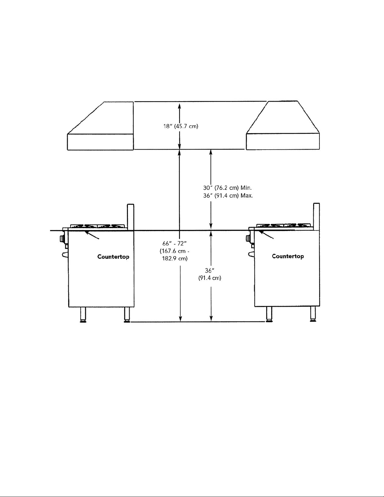
HEIGHT OF HOOD
The bottom of the hood should be 30” (76.2 cm) min. to 36” (91.4 cm) max. above the countertop. This
would typically result in the bottom of the hood being 66” (167.6 cm) to 72” (175.3 cm) above the floor. The bottom
of the hood should never be more than 72” (182.9 cm) above the floor or more than 36” (91.4 cm) above the
countertop. These dimensions provide for safe and efficient operation of the hood.
WALL INSTALLATION
ISLAND INSTALLATION

INSTALLING HOOD CANOPY
Center the canopy and attach to wall. Secure
the hood to wall with mounting screws
provided. Make sure that the mounting screws
are driven into the framing and not just the
drywall. Use additional mounting screws (and
wall anchors if necessary) in the other holes.
NOTE: BECAUSE OF THE WEIGHT OF THE
HOOD - MAKE SURE THAT THE MOUNTING
SCREWS ARE DRIVEN INTO THE FRAMING
AND NOT JUST THE DRYWALL. IT MAY BE
NECESSARY TO DRILL ADDITIONAL HOLES
IN THE CANOPY FOR PROPER ALIGNMENT.
4
PREPARING FOR HOOD INSTALLATION
Plan where the ductwork will be located. See pages 11-14 for rough-in dimensions. Install proper-sized duct work,
and roof or wall cap for the type of blower you are using. Recommended hood locations for the most common
installations are shown on page 2.
Adjust your measurements for various heights of ceilings, soffits, cabinets, or ranges/rangetops.
Roof Cap
10” Round Duct
1200 CFM
Single Blower
Interior Power -
Typical Ductwork
Exterior Blower
10” Round
Duct
Duct Cover or
Soffit
900, 1200, or
1500 CFM
Exterior Power
Typical Ductwork
ELECTRICAL SUPPLY
Run 120 VAC electrical power cable from service panel to installation location. See “Basic Specifications” on page 15
for the maximum amp requirements.
(BEFORE INSTALLING ISLAND HOOD CANOPY, SKIP TO PAGE 5)
Top Mounting Holes
(Soffit or duct cover)
Duct Cover or
Soffit
Roof Cap
7” Round Duct
300 -or 600 CFM
Single Blower
Interior-Power
Typical Ductwork
Duct Cover
or Soffit
5
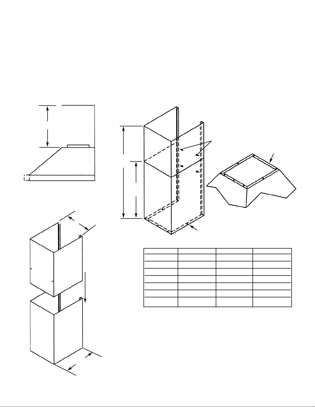
INSTALLING THE WALL HOOD DUCT COVER
1. Measure from top of the canopy to ceiling and subtract 1/8” (0.3 cm) for clearance.
2. Place the duct cover top inside the duct cover base and lower until desired height is found. (To eliminate
scratches, make a mark on the duct cover top for the desired lowering point by subtracting 18” (45.7 cm) from the
total height needed.)
3. Use the retaining nuts and bolts to fasten in place.
4. Slide the duct cover in place and fasten from inside canopy using the sheet metal screws provided.
5. Note: For installations with ceilings above 9’ (22.9 cm), use optional duct extensions. See product literature for
details
Item 1
C
12”
(30.5 cm)
Duct Cover
To p
Duct Cover
Base
Item 2
A
Mín.
B
Max.
Item 4
Item 3
Canopy Top
Model “A” Mín. “B” Max “C”
VCWH3048 12” (30.5 cm) 24” (61.0 cm) 12” (30.5 cm)
VCWH3648 12” (30.5 cm) 24” (61.0 cm) 12” (30.5 cm)
VCWH4248 12” (30.5 cm) 24” (61.0 cm) 12” (30.5 cm)
VCWH4848 12” (30.5 cm) 24” (61.0 cm) 18” (45.7 cm)
VCWH5548 12” (30.5 cm) 24” (61.0 cm) 18” (45.7 cm)
VCWH6048 12” (30.5 cm) 24” (61.0 cm) 24” (61.0 cm)
VCWH6648 12” (30.5 cm) 24” (61.0 cm) 24” (61.0 cm)

6
INSTALLING THE ISLAND HOOD DUCT COVER
1. Cut hole in ceiling for 10” diameter duct.
2. Attach duct cover mounting bracket to the top of the duct cover with the nuts and screws provided.
3. Using the screws provided, mount the bracket to the ceiling. Make sure the area is able to support at least 200 lbs.
(Center duct cover with 10” diameter hole.)
4. Run duct work down to bottom edge of duct cover and secure in place. Make sure the duct does not stick down
past the cover.
5. Attach duct cover to the top of the canopy with screws provided. Additional support can be added by running
threaded rod from the ceiling to the top of the canopy at all four corners. Holes must be drilled.
6. Install blower. (See ventilation kit installation.)
Model “A” “B” “C”
VCCI3608 12” (30.5 cm) 6” (15.2 cm) 12” (30.5 cm)
VCCI3609 12” (30.5 cm) 6” (15.2 cm) 24” (61.0 cm)
VCCI3610 12” (30.5 cm) 6” (15.2 cm) 36” (91.4 cm)
VCCI4208 12” (30.5 cm) 6” (15.2 cm) 12” (30.5 cm)
VCCI4209 12” (30.5 cm) 6” (15.2 cm) 24” (61.0 cm)
VCCI4210 12” (30.5 cm) 6” (15.2 cm) 36” (91.4 cm)
VCCI5408 18” (45.7 cm) 9” (22.7 cm) 12” (30.5 cm)
VCCI5409 18” (45.7 cm) 9” (22.7 cm) 24” (61.0 cm)
VCCI5410 18” (45.7 cm) 9” (22.7 cm) 36” (91.4 cm)
VCCI6608 24” (61.0 cm) 12” (30.5 cm) 12” (30.5 cm)
VCCI6609 24” (61.0 cm) 12” (30.5 cm) 24” (61.0 cm)
VCCI6610 24” (61.0 cm) 12” (30.5 cm) 36” (91.4 cm)
 Loading...