

Viking VCBB360R, VCBB362R, VCBB360L, VCBB362L Service Manual

SERVICE NOTEBOOK
REFRIGERATOR
VCBB360R / VCBB362R (Right) – VCBB360L / VCBB362L (Left)
VIKING RANGE CORPORATION, P.O. DRAWER 956, GREENWOOD, MS. 38930 - USA

Table of Contents
Technical Information................................................................................................................... 3
Display Panel................................................................................................................................ 4
Display Panel Operation............................................................................................................... 5
Electronic Functional Description................................................................................................ 6
Power Disconnect Switch
Showroom Switch
Alarms
Temperature Control Operation.................................................................................................... 7
Adaptive Defrost Operation.......................................................................................................... 8
Program Mode............................................................................................................................... 9
Electronic Testing......................................................................................................................... 11
Electronic Function Description................................................................................................... 12
Wiring Diagram............................................................................................................................ 14
Wiring Schematic (Complete)........................................................................................................ 15
Wiring Schematic (Freezer Compartment)..................................................................................... 16
Wiring Schematic (Refrigeration Compartment)............................................................................ 17
Wiring Schematic (Refrigerator and Freezer Compartment).......................................................... 18
Wiring Schematic (Adaptive Defrost)............................................................................................. 19
Component Specification.............................................................................................................. 20
Component Testing....................................................................................................................... 23
Troubleshooting Charts................................................................................................................. 31
System Diagnosis.......................................................................................................................... 33
Service Procedures........................................................................................................................ 34
Refrigerant Flow............................................................................................................................ 40
Cabinet Airflow............................................................................................................................. 41
Machine Compartment Air Flow................................................................................................... 42
Typical External Sweat Pattern..................................................................................................... 43
Disassembly Procedures................................................................................................................ 44
Ice Maker....................................................................................................................................... 47
Ice Maker Troubleshooting Chart.................................................................................................. 52
Ice Maker Wiring Diagram and Part Layout.................................................................................. 55
2
Technical Information – Refrigerator
To avoid electrical shock which can cause severe personal injury or death, disconnect
power to refrigerator using power switch before servicing. Wires removed during
disassembly must be replaced on proper terminals to insure correct earth ground and
polarization. After servicing, reconnect power using power switch.
Refrigerator Center Freezer
Compartment Food Compartment
Percent Run Cycle/24 hr Average temperature Food Average
Kw/24 hr ± 0.4 Time ± 10% ± 25% ± 3°F Temperature ± 3°F
Ambient° F 65° 90° 110° 65° 90° 110° 65° 90° 110° 65° 90° 110° 65° 90° 110°
1.2 2.3 4.2 28 52 100 30 32 0 39 39 45 3 3 3
Temperature Relationship Test Chart
T-3 Suction Average Total Suction Pressure Head Pressure
T-1 Outlet ± 3° F T-1 Inlet ± 3° F Line Wattage ±10% ± 2 PSIG ± 5 PSIG
± 7°F
Ambient °F 65° 110° 65° 110° 65° 110° 65° 110° 65° 110° 65° 110°
-14 -14 -14 -14 25 103 157 168 0 0 110 157
3
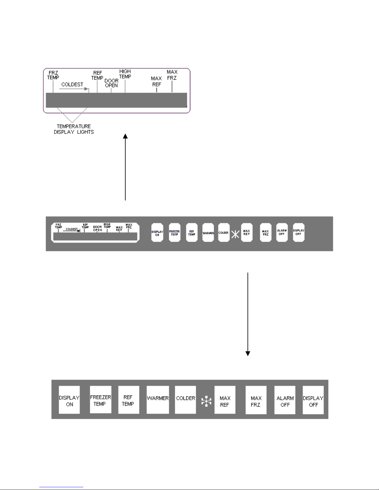
Display Panel Keyboard
Display Panel
4

Display Panel Operation
Keyboard Tone
Entry Tone
Indicates a pad was pressed, command read
and accepted, Turn off entry tone by pressing
and holding Display On pad for 3 to 5 seconds.
Command Accepted Tone
Three short tones indicate command accepted.
Display On Pad
1. Activates control panel. Control panel
remains active at least 10 minutes .
2. Turns off Power Up Alarm (flashing lights)
after power is firs t p lug ged in or af ter p o wer
outage.
All pads, except Alarm Off, are inactive
Note:
until display On is pressed.
Freezer Temp Pad
Activates freezer temperature settings mode.
1. Fr ee zer indic ator light will glow. Freezer
temperature setting will be displa yed.
Factory setting is 5.
2. Change freezer temperature setting by
pressing Warmer or Colder pad.
Ref Temp Pad
Activates refrigerator temperature settings
mode.
!. Refrigerator indicator light will glow.
Refrigerator temperature setting will be
displayed. Factory setting is 5.
2. Change refrigerator temperature setting by
pressing Warmer or Colder pad.
Warmer Pad
Raises temperature settings one bar at a time.
If entry tone is on, tone will sound at each bar
level until top level is reached.
!. Turn on temperature setting function of
control panel by pressing Warmer pad.
2. Press and hold Warmer pad to raise
temperature setting at a faster rate.
Colder Pad
Lowers temperature sett ing one b ar at a tim e. If
entry tone is on, tone will sound at each bar
level until bottom level is reached.
1. Turn on temperature setting function of
control panel be pressing Colder pad.
2. Press and hold Colder pad to lower
temperature setting at a faster rate.
Max Frz Pad
Activates Maximum freezer mode s etting freezer
temperature to coldest setting for 24 hours or
until Max Frz pad is pressed again.
1. Freezer indica t or light wi ll g lo w.
2. To adjust maximum freezer mode time
refer to Program Mode B functions.
Max Ref Pad
Activates Maximum refrigerator mode setting
refrigerator to coldest sett in g f or 24 hours or until
Max Ref pad is pressed again.
!. Refrigerator indicator light will glow.
2. To adjust maximum refrigerator time refer
to Program Mode B functions.
Alarm Off Pad
Turns off alarm signals . See Alarms section to
interpret alarm signals.
!. Press and hold Alarm Off pad for 3 seconds
to deactivate Door Open alarm. To
reactivate Door Open alarm, press and
hold Alarm Off pad for 3
seconds.
2. If Alarm Off pad is pressed and condition
causing alarm is not corrected, alarm will
reset .
**
Activates Program Mode. See Program Mode
section for description of functions available.
1. Open refrigerator door.
2. Press Display On pad.
3. Press * pad.
4. Within 6 seco nds press the following pads
in this sequence; Max Ref, Max Frz, Max
Ref, Max Frz.
5. T one will sound 3 times and contr ol will be
in program mode A.
Display Off Pad
1. Deactivates control panel
2. Deacti vat es tem per ature in dic at ion area of
control panel.
5
Electronic Functional Description
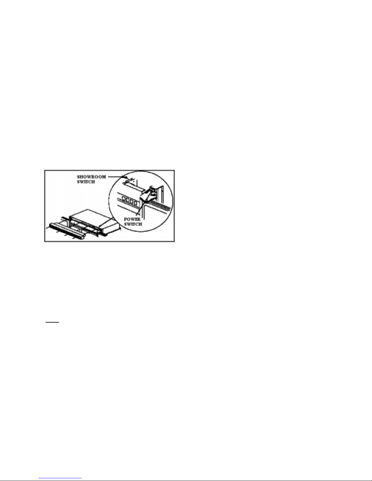
Power Disconnect Switch
Use power disconnect switch to disconnect
power without unplugging refrigerator. Power
disconnect switch is located behind air grille on
top right side. Refrigerator is shipped with
power disconnect switch in the on position.
Showroom Switch
Showroom switch allows electronic controls and
interior lights to function independently of
refrigeration system. Showroom switch is
located behind air grille to right of control panel.
Refrigerator is shipped with showroom switch in
the unit run position.
Alarms
Power Up Alarm
After power is initially plugged in, after a power
loss, or if power switch is turned off, all
temperature indicator lights will flash until
Alarm Off or Display On is pressed.
Note
: All settings return to default factory
settings.
Door Open Alarm
Alarm tone sounds and indicator lights blink if
either refrigerator or freezer door is open more
than 3 minutes.
1. Turn off Door Open alarm by pressing
Alarm Off pad or by closing door.
2. Deactivate door open alarm be pressing
Display On pad and then press and hold
Alarm Off pad for 3 seconds.
3. Door alarm delay can be adjusted in
Program Mode B.
High Temperature Alarm
Alarm sounds and indicator light shows if
freezer or refrigerator temperature has gone
above critical level and remains warm for 2
hours. Alarm tone stops if temperature falls
again.
!. Critical temperature for freezer is +15°F;
for refrigerator critical temperature is
+55°F.
2. Press Alarm Off to turn off alarm.
Thermistor Alarm
Alarm sounds and freezer or refrigerator
indicator light shows and temperature indicators
4 through 7 will turn on in sequence if either
thermistor circuit opens. Refer to Temperature
Control Operation Section and Electronic
Testing Section.
!. Press Alarm Off pad to turn off alarm.
2. Alarm will reset for normal operation. If
condition has not been corrected, alarm will
sound again.
6
Electronic Functional Description
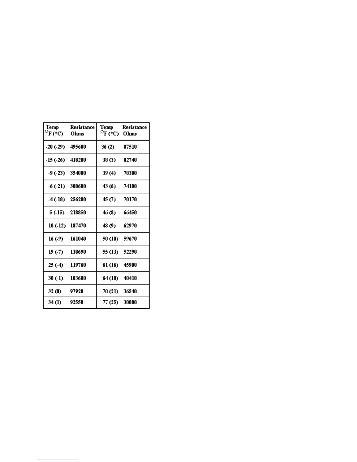
Temperature Control Operation
For any temperature setting, outputs will be
turned off/on based on cut-in, cut-out
temperatures determined by resistance levels of
freezer and refrigerator the r mistors.
Refrigerator and Freezer Thermist or
As temperature decreases, resistance increases.
As temperature increases, resistance decreases.
Open thermistor or thermistor circuit will result
in failure of refrigerator to cool.
Shorted thermistor will cause refrigerator to run
100 percent of time except for defrost cycle.
• Freezer temperature setting and
thermistor value will determine if
compressor/condenser fan and
evaporator fan switches are open or
closed. Compressor/condenser fan
switch must be open for 6 minutes
before switch can close again
(compressor dwell time.)
• Refrigerator temperature setting and
thermistor valve will determine if fresh
food fan switch is open or closed.
• Cut-out and cut-in temperature values
must be reached and maintained for 15
minutes before output state will change
(digital delay).
• Refrigerator and freezer control
calibration can be adjusted in Program
Mode B.
Factory set freezer and refrigerator
settings.
7

Electronic Functional Description
Adaptive Defrost Operation
Defrost occurs after predetermined length of
compressor run hours. Compressor run time
between defrost changes, or adapts, depending
upon recent history of defrost lengths (time it
takes for defrost terminator to open after defrost
heater has been turned on).
• Defrost terminator opens at 55°F (-
13°C).and closes at 20°F (-7°C).
• Compressor run time between defrost
(CRDT) will be one of 3 values under
normal operation CRDT 1 (8 hours) or
CRDT 2 (12 hours) or CRDT 3 (15
hours).
If defrost length is low (DT-LO defined
as 21 minutes) indication small frost
load, CRDT for next defrost cycle is
advanced to next level.
If defrost length is high (DI-HI defined
as 24 minutes) indicating large frost
load, CRDT for next defrost cycle is
lowered to next level.
If defrost length is between 21 and 24
minutes, CRDT for next defrost cycle
remains the same.
Initial value at power up CRDT is 4 hours.
• Vacation Mode CRDT equals 96
hours. Vacation Mode CRDT is
interrupted with door openings.
Defrost interval will revert back to
interval before vacation mode.
Three things must occur to reach
Vacation Mode CRDT.
1) Defrost interval must be
CRDT 3 (16 hours).
2) Both refrigerator and
freezer doors must have
remained closed since last
defrost cycle.
3) Defrost thermostat must
have opened in less than 21
minutes during last defrost
cycle.
• Six minutes dwell time occurs after
defrost terminator opens before
compressor and condenser fan
motor will operate. Ten minutes
dwell time occurs after defrost
terminator opens before evaporator
fan motor will operate. Dwell time
can be bypassed be disconnecting
power to the unit for 30 seconds.
• Conventional defrost can be selected
in Program Mode B.
8
Program Mode
Accessing Program Mode
Two programming modes are available. Mode A
allows reading refrigerator and freezer thermistor
temperatures. Mode B is used for all other
programmable functions.
1. Open refrigerator door.
2. Press Display On pad.
3. Press * pad.
4. Press the following sequence of pads within 6
seconds; Max Ref, Max Frz, Max Ref, Max
Frz.
5. When access is granted, tone will sound three
times and control will be in Program Mode A.
Unmarked indicator light will illuminate.
6. T o ggle to Program Mode B by pressing Display
On pad. Unmarked indicator light is off.
EEPROM Update in Control Memory
EEPROM is permanent programmable memory of
the control panel.
• Entry tone, door audio alarm and status are
stored in EEPROM after control is
deactivated.
• Information stored in EEPROM me mory is
not affected be power loss.
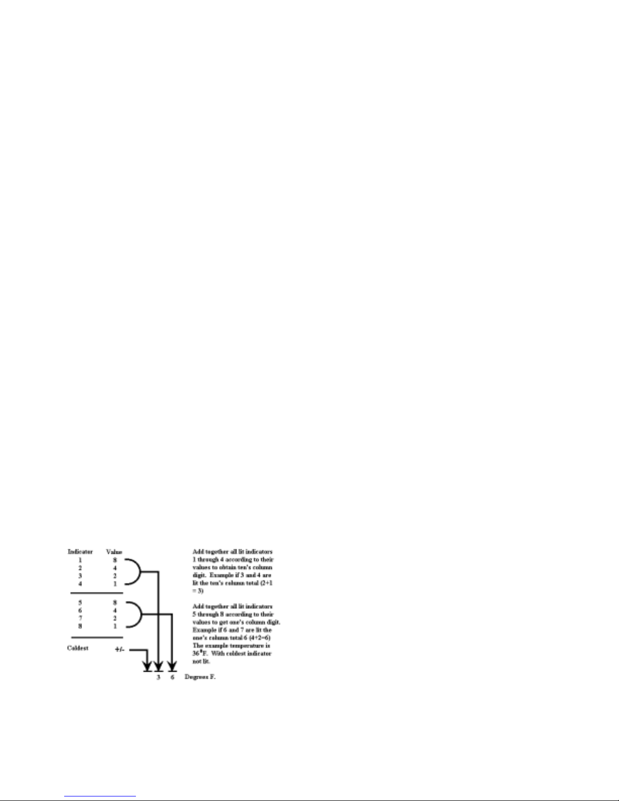
Mode A Function
Reading Temperature Display
Temperature display will show thermistor
temperature in binary coded decimal format (BCD).
Indicator lights 1 through 4 represent the ten’s digit
with 1 being the most significant bit. Indicator lights
5 through 8 represent one’s digit with 5 being the
most significant bit. Positive and negative are shown
be indicator light 9. Light glows to show negative
value.
Freezer Thermistor Temperature
1. Choose freezer thermistor temperature
display be pressing Freezer Temp pad.
2. Freezer thermistor temperature displays.
Refrigerator Thermistor Temperature
1. Choose refrigerator thermistor temperature
display be pressing Ref Temp pad.
2. Refrigerator thermistor temperature displays
Mode B Functions
Automatic Keyboard Functions
Activate and deactivate keyboard by toggling Display
Off pad. If high temperature indicator glows,
keyboard will disable after 10 minutes. If high
temperature indicator is off, keyboard is always
enabled. DO NOT LEAVE KEYBOARD IN
ENABLE MODE AFTER PROGRAMMING IS
COMPLETE.
Door Alarm Delay
1. Press Alarm Off pad. Door open indicator
will glow. One temperature indicator should
glow indicating present delay setting in
minutes (indicator 1 means 1 minute, 2
means 2 minutes, etc.). Default delay is 3
minutes.
2. Press Warmer pad to decrease delay by 1
minute.
3. Press Colder pad to increase delay by 1
minute.
Max Ref Run Time Duration
1. Press Max Ref pad. Max Ref light will
glow. One temperature indicator should
glow indicating present Max Ref run
time duration in 2 hour increments
(indicator 1 means 2 hours, 2 means 4
hours, etc.) . Default del ay is 10 ho urs.
2. Press Warmer pad to decrease Max Ref
duration by 2 hours.
3. Press Colder pad to increase Max Ref
duration by 2 hours.
9
Program Mode
Max Frz Run Time Duration
1. Press Max Frz pad. Max Frz light will
glow. One temperature indicator should
glow indicating present Max Frz run time
duration in 4 hour increments (indicator
1 means 4 hours, 2 means 8 hours, etc.)
Default delay is 24 hours.
2. Press Warmer pad to decrease Max Frz
duration by 4 hours.
3. Press Colder pad to increase Max Frz
duration by 4 hours.
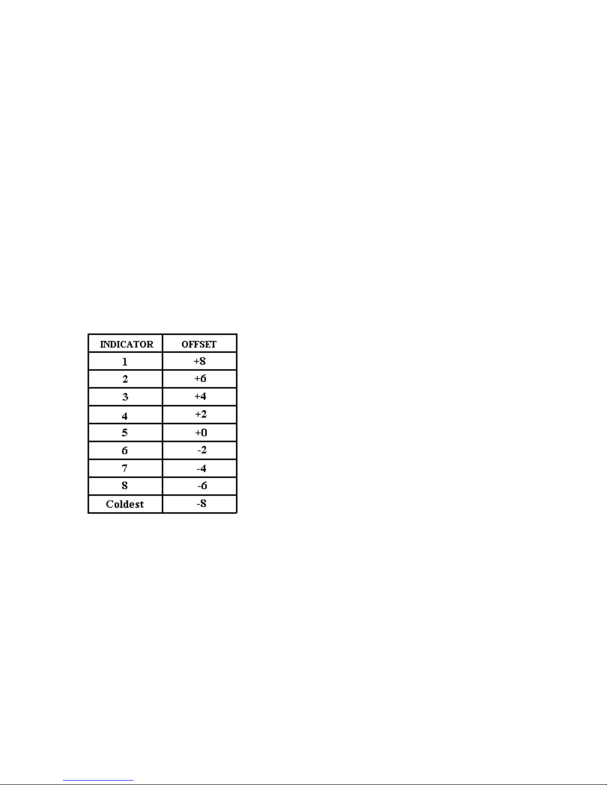
Temperature Offset Calibration
Offset amount adjusts temperatures for
refrigerator cut-ins and cut-outs by the amount
of offset. The chart below shows the indicator
and the amount of offset from the factory default
setting.
• Setting refrigerator Temperature Offset.
Press Ref Temp pad. Refrigerator
indicator and one indicator will glow.
Press Warmer pad to move offset to the
next warmer setting. Press Colder pad
to move to the next colder setting.
Factory default refrigerator offset is +2.
• Setting Freezer Temperature Offset
Press Freezer pad. Freezer temperature
indicator and one indicator will glow.
Press Warmer pad to move offset to the
next warmer setting. Press Colder pad
to move offset to the next colder setting.
Factory default freezer offset is 0.
Defrost Mode Selection
Toggle (*) pad to select adaptive or conventiona l
defrost mode. Vacation indicator glows when
adaptive defrost has been selected. If vacation
indicator is off, conventional defrost is selected.
Conventional defrost uses 8 hour CRDT value.
Forced Defrost
Defrost can be forced to start by pressing and
holding the Alarm Off pad for 3 seconds.
Program changes will be saved permanently in
EEPROM and program mode will exit to Run
Mode.
Forced Pull down (Compresso r Start )
Compressor start can be forced by pressing and
holding Max Frz for 3 seconds. Program
changes will be saved permanently in
EEPROM. Compressor, evaporator fan, damper
heater, and condenser fan will come on.
Exiting Program Mode
Press Display On pad for 3 seconds to exit
Program Mode. Tone will sound three times.
Changes made in Program Mode will be
permanently saved in EEPROM.
Note: If no pad is pressed for 10 minutes,
Program Mode will be automatically exited.
However, no changes will be saved if Program
exits automatically.
10

Electronic Testing
Electronic Testing Mode
Forced Defrost Start
1. Press Display On pad to activate control
panel.
2. Simultaneously press and hold Max Ref and
Display Off pads for 3 seconds.
Forced Compressor Start
1. Press Display On pad to activate control
panel.
2. Simultaneously press and hold Max Frz and Display Off pad for 3 seconds.
Open Thermistor Detect
Alarm sounds and freezer or refrigerator
indicator light shows and temperature indicators
4 through 7 will turn on in sequence if either
thermistor circuit opens. Refer to Temperature
Control Operation Section and Electronic
Testing Section.
1. Press Alarm Off pad to turn off alarm.
1. Check for line voltage on terminal E7 on
high voltage board. With refrigerator
door open (refrigerator light ON)
reading should be 120-VAC. With door
closed (refrigerator light OFF) reading
should be approximately 0 VAC. If
voltage does not change with light
switch and light is turning light off and
on red/white wire is broken between
switch and high voltage board.
2. Check for voltage on terminal E7 on
high voltage board. Output voltage
should toggle with toggling of light
switch. If output voltage does not
toggle, high voltage board needs
replacing.
3. If terminal 7 on high voltage board
changes with opening and closing of
door, orange wire in low voltage
harness is broken (check for continuity
between pin 7 on high voltage board and
pin 10 on low voltage board) or low
voltage board
2. Alarm will retest for normal operation.
If condition has not been corrected,
alarm will sound again.
Evaporator Fan Suppression
The evaporator fan will turn off every time
either refrigerator or freezer door is open.
To test if this function is operating:
1. Perform forced pull down procedure as
noted above--evaporator fan should be
on.
2. Open the refrigerator or freezer door-the fan should turn off.
3. Push the light switch off-the evaporator
fan should start.
If fan does not toggle off and on when
refrigerator light switch is turned off and on it
has been determined evaporator fan motor
operational, perform following tests to
determine failure:
1. Check for line voltage on terminal E8 on
high voltage board. With freezer door
open, reading should be 120VAC. With
door closed, reading should be
approximately 0 VAC. If voltage does not
change with light switch and light switch is
turning light off and on, violet/white wire is
broken between switch and high voltage
board.
2. Check for voltage on pin 7 on pin
connector of high voltage board. Output
voltage should toggle with toggling of
light switch. If it does not toggle, high
voltage board needs replacing.
3. If voltage on pin 7 on pin connector on high
voltage board changes with opening and
closing of door, orange wire in low
voltage harness is broken (check for
continuity between pin 7 on high voltage pin
connector and pin 10 on low voltage board)
or low voltage board needs replacing.
needs replacing.
11
Electronic Function Description
WARNING: To avoid electrical shock which can cause severe personal injury or death, disconnect
power to r efrigerator using power swit ch before ser vicing. Wires removed during d isassembly must be
replaced on proper terminals to insure earth ground and polarization. After servicing, reconnect power
using power switch.
12

Electronic Function Description
WARNING
To avoid electrical shock which can cause severe personal injury or death, disconnect power
to refrigerator using power switch before servicing. Wires removed during disassembly must
be replaced on proper terminals to insure correct earth ground and polarization. After
servicing, reconnect power using power switch
Refrigeration and Defrost Component Checks Made at High Voltage Board
Low voltage board input W1 to D11 approximately -25VDC
E10 to E9 (Neutral) or ground approximately 120VDC
Compressor/condenser fan motor “ON” = E4 to E9 (Neutral) or ground approximately 120VDC
“OFF” = E4 to E9 (Neutral) or ground
Compressor/condenser fan motor “CLOSED” = R7 to ground approximately -11VDC
relay “OPEN” = R7 to ground approximately -25VDC
Evaporator fan motor relay “CLOSED” = R8 to ground approximately -11VDC
“OPEN” = R8 to ground approximately -25VDC
Evaporator fan motor “ON” =E2 (Neutral) or ground approximately 120VDC
“OFF” = E2 (Neutral) or ground 0VDC
Defrost heater “ON” = E6 to E9 (Neutral) or ground approximately 120VDC
“OFF” = E6 to E9 (Neutral) or ground 0VDC
Defrost heater relay “CLOSED” = R9 to ground approximately -11VDC
“ OPEN” = R9 to ground approximately -25VDC
Defrost terminator “CLOSED” =E5 to E9 (Neutral) ground approximately 120VDC
“OPEN” = E5 to E9 (Neutral) or ground 0VDC
DC fan output voltage from “ON’ = E1 to ground approximately -25VDC
high voltage board to fresh food fan “OFF” = E1 to ground 0VDC
or condensate evaporator fan
DC fan input voltage “ON” =R10 to ground approximately -11VDC
signal to high voltage board from “OFF” = R10 to ground approximately -25VDC
low voltage board for fresh food
fan and for condensate evaporator
Filament voltage at pin 11 and 12 = less than 5VDC
13
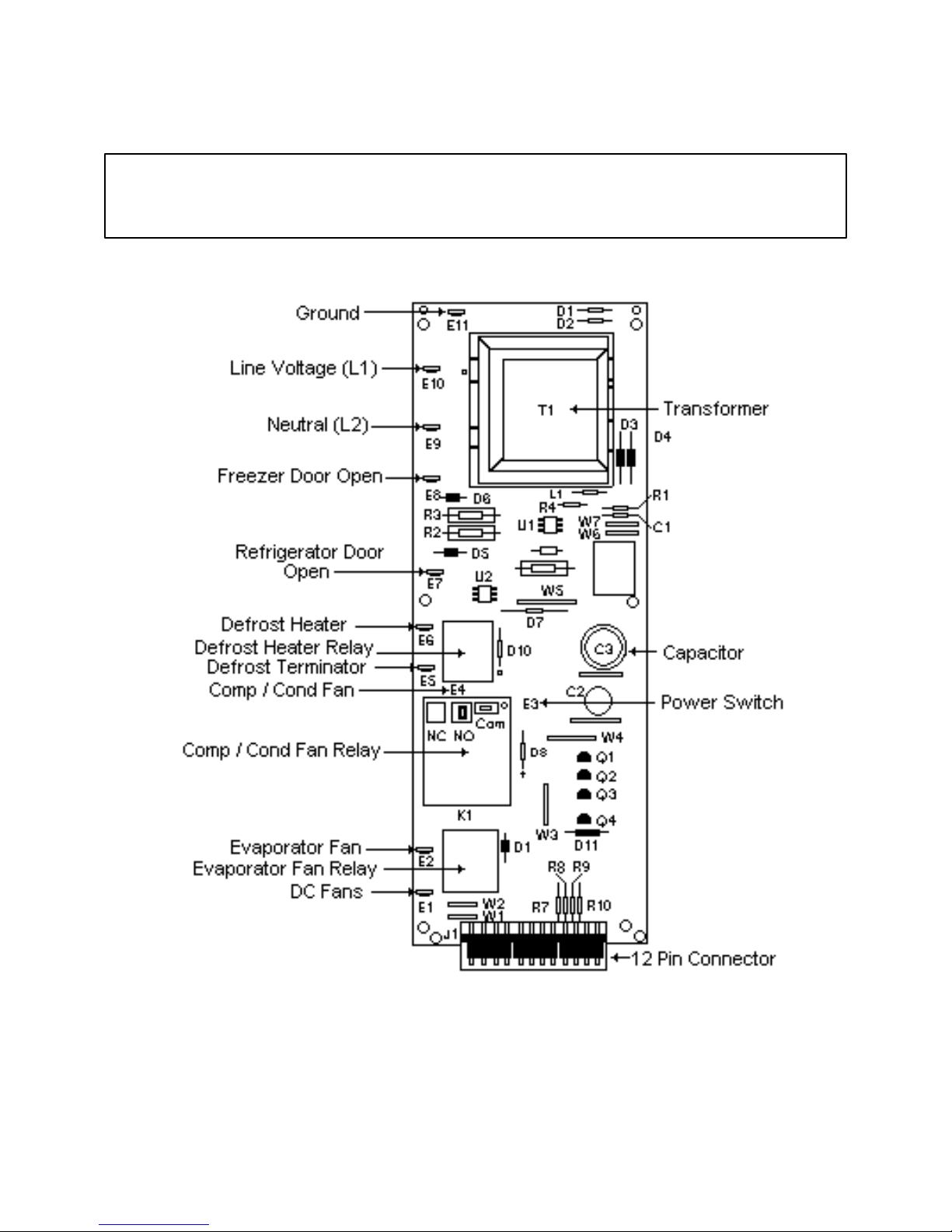
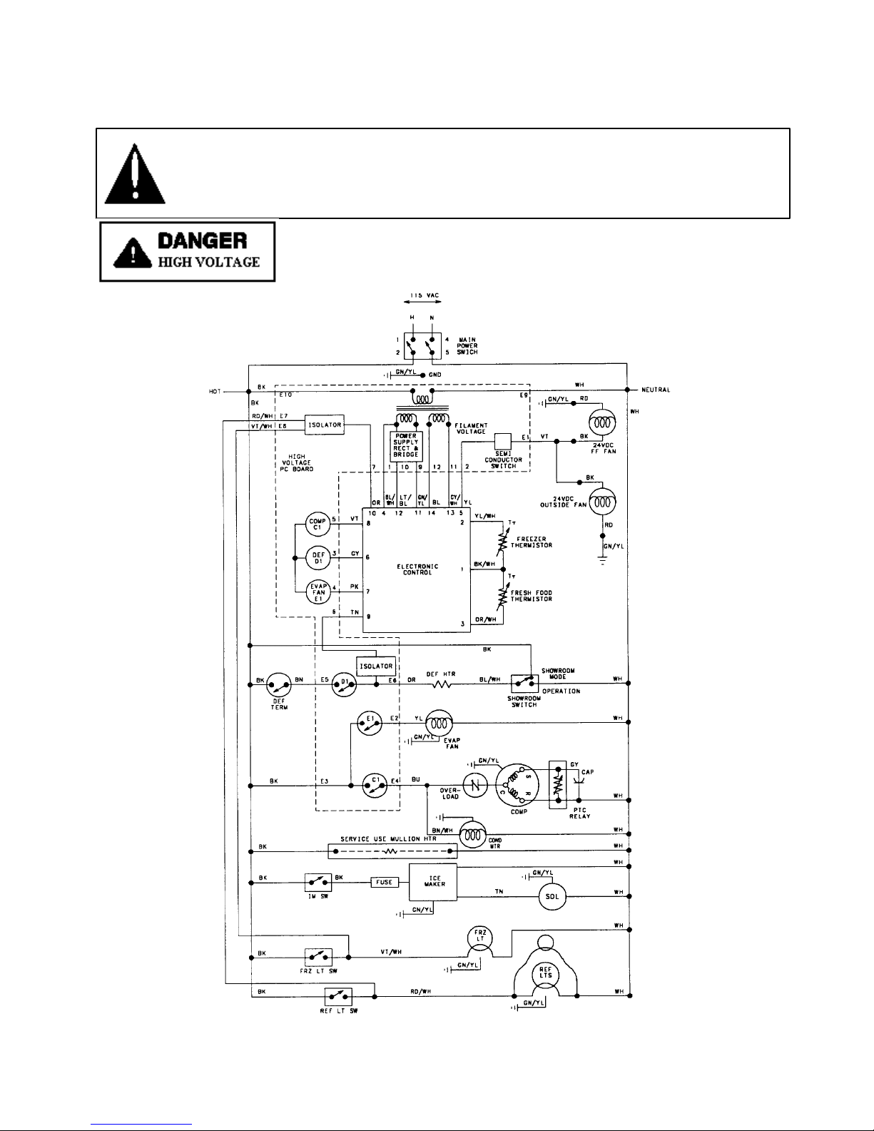
Wiring Diagram
WARNING To avoid electrical shock which can cause severe personal injury or death,
disconnect power to refrigerator using power switch before servicing. Wires removed during
disassembly must be replaced on proper terminals to insure correct earth ground and
polarization. After servicing, reconnect power using power switch.
14
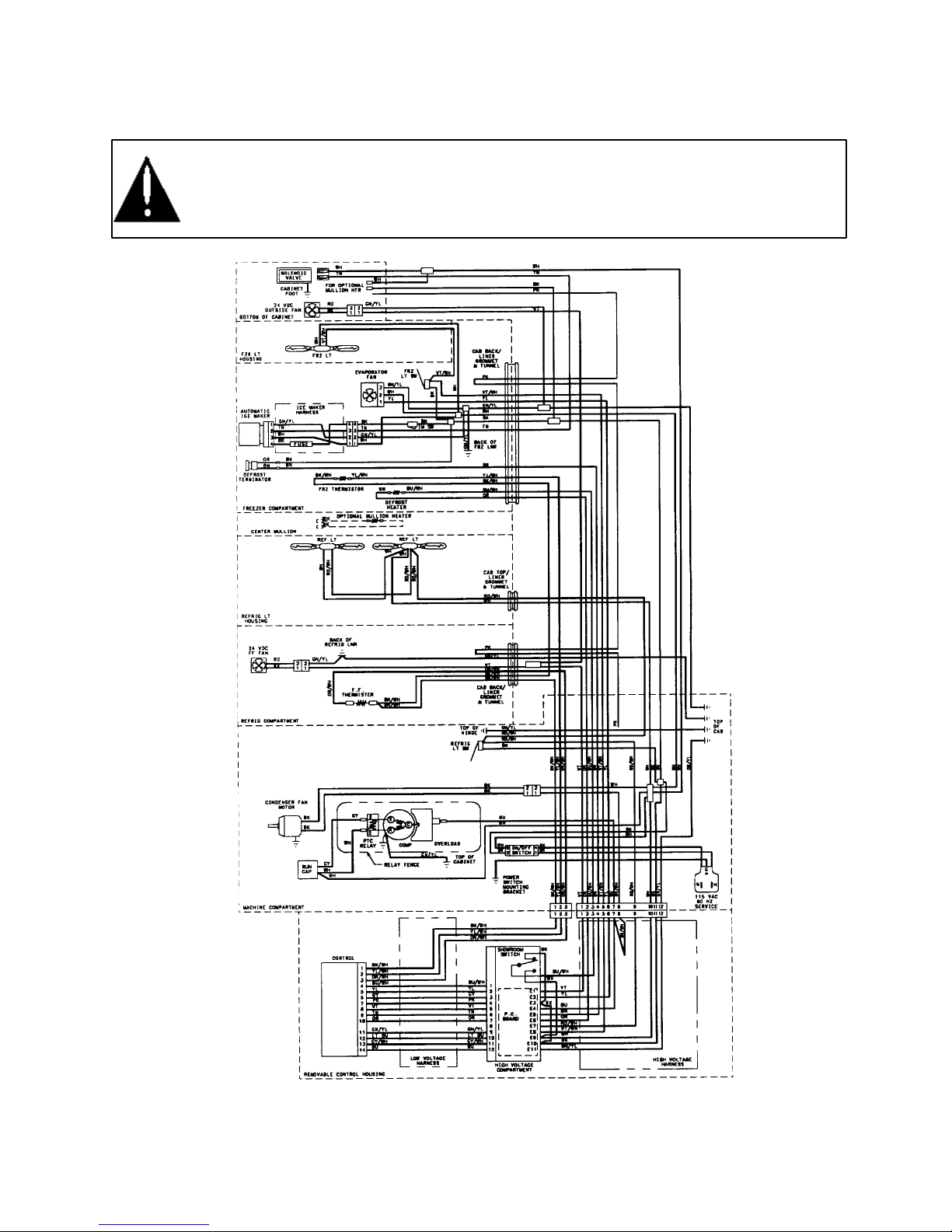
Wiring Schematic
To avoid electrical shock which can cause severe personal injury or death, disconnect power
to refrigerator using power switch before servicing. Wires removed during disassembly must
be replaced on proper terminals to insure correct earth ground and polarization. After
servicing, reconnect power using power switch
15

Electronic Function Description
WARNING: To avoid electrical shock which can cause severe personal injury or death,
disconnect power to refrigerator using power switch before servicing. Wires removed during
disassembly must be replaced on proper ter minals to insure correct grounding and po larization.
After servicing, reconnect power using power switch.
Freezer Compartment Theory of Operation
As a freezer thermistor warm, the resistance decreases allowing low voltage signal to be sent to electronic
control. Electronic control sends two low voltage signals, one to the compressor relay coil (C1) and one
to the evaporator relay coil (E1).
When both relay coils are energized and both relay contacts are closed, high voltage circuits to evaporator
fan motor and compressor / condenser fan motor are complete.
As thermistor cools during refrigeration cycle, resistance through thermistor increases blocking low
voltage signal to electroni c control interrupting circui t.
16

Electronic Function Description
WARNING: To avoid electrical shock which can cause severe personal injury or death,
disconnect power to refrigerator using power switch before servicing. Wires removed
during disassembly must be replaced on proper terminals to insure correct grounding
and polarization. After servicing, reconnect power using power switch.
Refrigeration Compartment Theory of Operation
As fresh food thermistor warms, resistance decreases allowing low voltage signal to be sent to the
electronic control. El ectronic control sends a low voltage signal, to semiconductor switch for DC fresh
food fan and DC condensate evaporator fan.
Both fans begin operating. Fresh food fan circulates freezer air into fresh food compartment. Condensate
evaporator fan circuilates air over condensate drain pan aiding in evaporation.
As fresh food thermistor cools, resistance increases blocking low voltage signal to electronic control
interrupting circuit to DC fresh food fan and DC condensate evaporation fan.
17
 Loading...