

Viking VCBB360 Installation Instructions Manual
VIKING RANGE CORPORATION
INSTALLATION
Greenwood, Mississippi (MS) 38930 USA
111 Front Street
(601) 455-1200
INSTRUCTIONS
BUILT-IN BOTTOM MOUNT REFRIGERATOR
IMPORTANT - PLEASE READ AND FOLLOW
Make sure that incoming voltage is the same as unit rating. An electric rating plate specifying voltage, hertz, wattage, amps,
and phase is attached to the product.
To reduce the risk of fire, electric shock, or injury to persons, installation work and electrical wiring must be done by qualified
people in accordance with all applicable codes and standards, including fire-rated construction.
GENERAL INFORMATION
Most of the refrigerator’s weight is at the top.
EXCESSIVE WEIGHT HAZARD
Use two or more people to move and install refrigerator.
Failure to follow this instruction can result in back or other injury.
Extra care is needed when moving the
refrigerator to prevent tipping. Keep
cardboard shipping piece or plywood under
refrigerator until it is installed in the operating
position.
It is your responsibility to :
-comply with installation specifications and dimensions
-properly install refrigerator
-make sure that you have these materials which are necessary for proper installation:
1/4” (6 mm) copper tubing with shutoff valve
1/4” (6mm) compression fitting
-assure that floor will support refrigerator (more than 600 lbs. [272 kg.]), door panels and contents
-provide a properly grounded electrical outlet
-assure that location will permit appliance doors to open 90
o
minimum
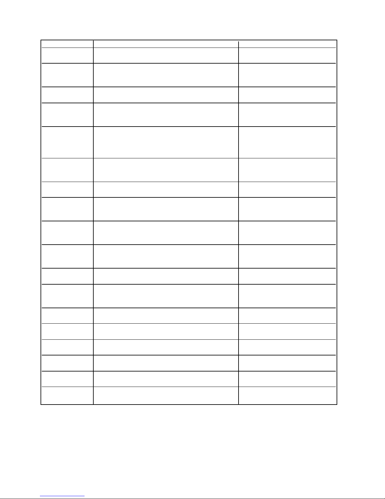
CUTOUT DIMENSIONS
Diagram A Description Dimension
A Width of lag bolt location 1” (2.54 cm)
B Distance from right side of cutout
C Width of receptacle location 27 1/2” (69.9 cm)
D Distance from right side of cutout
E Height to top of receptacle location and
F Height to bottom of receptacle
G Height of cutout (min.) 84” (213.4 cm)
H Depth of water line location
to left lag bolt location 32 9/16” (82.7 cm)
to right lag bolt location 3 3/8” 8.6 cm)
bottom of 2” x 4” (5.1 cm x 10.2 cm)
mounting board (including cover plate) 80 1/2” (204.5 cm)
location(including cover plate) 75 1/8” (190.8 cm)
on side wall 1” (2.54 cm)
I Position of water line location on
back wall 7 5/8” (19.4 cm)
J Width of water line location on
back wall 6 3/4” (17.1 cm)
K Height of water line location on side wall 5/8’ (1.6 cm)
L Height of water line location on
back wall 3” (7.6 cm)
M Depth of cutout (min.) 24” (61.0 cm)
N Do not place water line in this location 3 5/8” (9.2 cm)
O Width of water line location on floor 10 3/4” (27.3 cm)
P Water valve location See diagram
Q Depth of water line location on floor 10 1/2” (26.7 cm)
R Width of cutout (min.) 35 1/2” (90.2 cm)
Verify cutout depth is a minimum of 24” (61.0 cm) measuring from the rear of the cutout to the front. Minimum
refrigerator height is 83 1/4” (211.5 cm)with refrigerator adjusted to its lowest position. Maximum refrigerator height is
84 1/4” (214.0 cm) with refrigerator adjusted to its tallest position. Customize the installation if cutout height is more
than 84 1/4” (214.0 cm)and no cabinets are installed above the refrigerator. The electrical outlet must be installed
from 75 1/8” (190.8 cm) to 80 1/2” (204.5 cm) high and 0” to 21 1/2” (54.6 cm) from right side of cutout when facing
cutout.
2
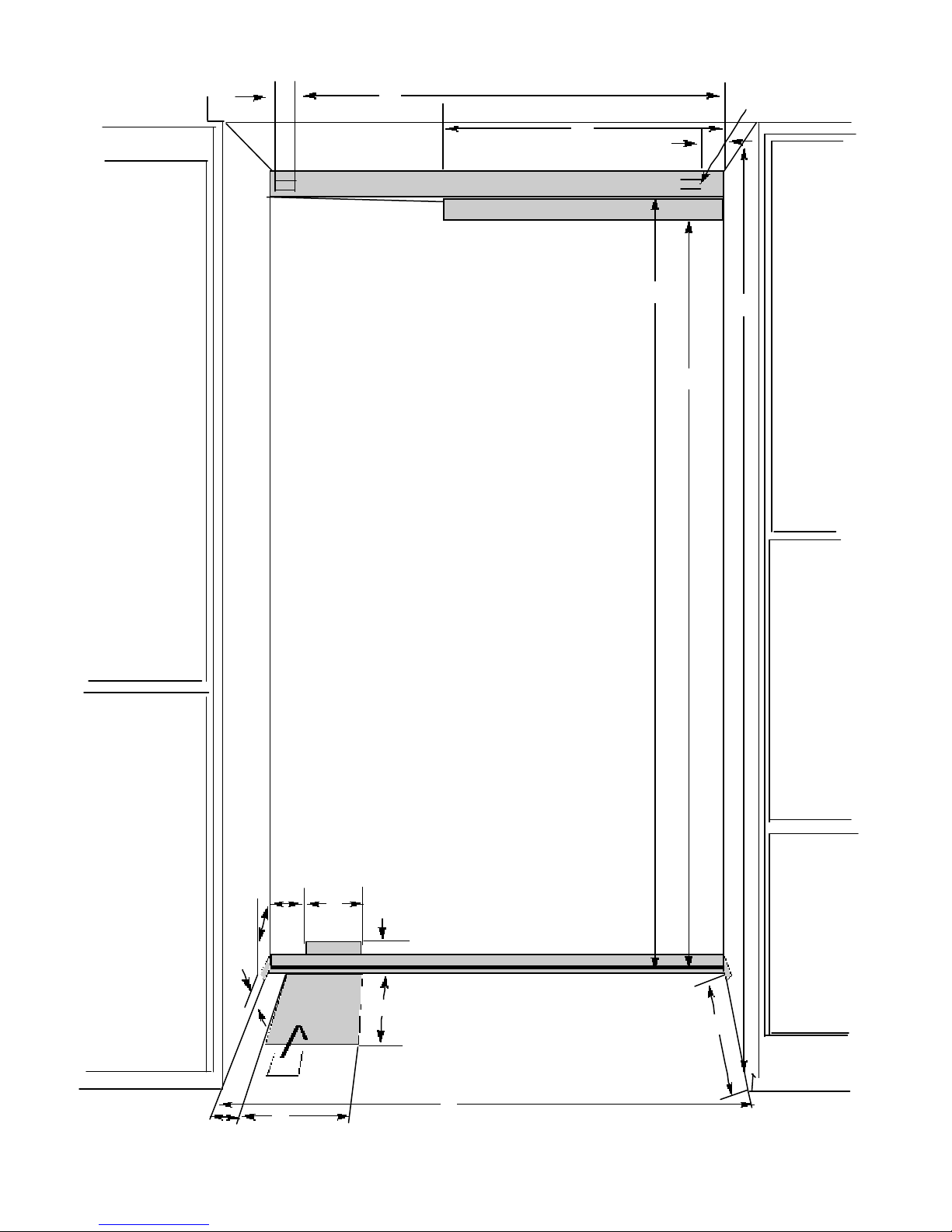
DIAGRAM A
A
B
Lag bolt
Location
C
2” X 4” Mounting Board
Receptacle Location
D
E
G
F
H
I
K
Water
line entry
P
N
O
J
L
Q
M
R
3
ELECTRICAL REQUIREMENTS
ELECTRICAL SHOCK HAZARD
Electrically ground refrigerator.
Do Not use an extension cord.
Failure to follow these instructions could result
in death, fire, or electrical shock
If codes permit a separate grounding wire is used,
it is recommended that a qualified electrician
determine that the grounding path is adequate.
Do Not ground to a gas pipe. Check with a
qualified electrician if you are not sure the
appliance is properly grounded. Do Not have a
fuse in the neutral or grounding circuit.
It is the customer’s responsibility:
To contact a qualified electrical installer.
To assure that the electrical installation is adequate and in
conformance with the National Electrical Code, ANSI/NFPA 70latest edition or Canadian Electrical Code C22.1-1982 and C22.2
No. 01982 (or latest edition), and all local codes and ordinances.
120 volt, 60-Hz, 15 amp, fused, electrical supply is required. It is
recommended that a separate circuit serving only this appliance be
provided. This appliance is equipped with a power supply cord
having a 3-prong grounding plug. To minimize possible shock
hazard, the cord must be plugged into a mating 3-prong,
grounding-type wall receptacle.
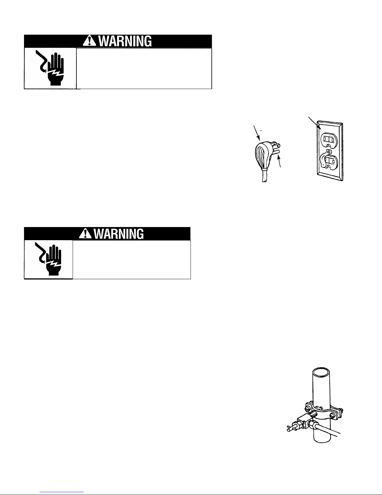
WATER SUPPLY REQUIREMENTS
Use only 1/4” (6 mm) copper tubing for water line. Do
ELECTRICAL SHOCK HAZARD
Some water may remain in line. Electric
drill must be grounded to prevent severe or
lethal shock if water is in line and enters drill
during use.
Not install copper tubing in area where temperatures
drop below 32
to refrigerator, flush at least 2 quarts (1.9 L) of water
through the copper tubing and into a bucket to get rid of
any particles in the water line.
3-prong grounding-type
3-prong
wall receptacle
grounding plug
grounding
plug
o
F (0oC). Before attaching copper tubing
To calculate length of 1/4” (6mm) O.D. copper tubing needed:
1. Locate a vertical 1/2” (1.2 cm) to 1 1/4” (3.2 cm)COLD water line near refrigerator area. A horizontal COLD water
line can be used if directions in Step 4 are carefully followed.
2. Measure distance from cold water line to refrigerator. Add 24” (61 cm) to this measurement.
To rough in water line:
3. Turn OFFmain water supply. Turn ONnearest faucet long enough to clear line of water.
4. Vertical cold water line: Use grounded electric drill or hand drill to drill 3/16” (4.5 cm) hole in an accessible location
in water line.
Horizontal cold water line: Use grounded electric drill or hand drill to drill 3/16” (4.5 cm) hole in the topof the water
line. This will keep sediment from collecting in valve.
5. Position washer over hole in water line. Turn saddle valve handle clockwise to expose
piercing lance a maximum of 3/16” (4.5 cm). Align piercing lance over hole in water line.
Place both halves of saddle valve bracket against water line. Turn saddle valve handle
clockwise until piercing lance enters hole in water line and is firmly seated. The saddle
valve is now in the closed position. Tighten packing nut. Evenly and firmly tighten
bracket screws so washer will make a water-tight connection. Do not overtighten screws;
copper tubing could be crushed.
6. Check that both ends of copper tubing are cut square. Slide compression nut and
sleeve onto copper tubing. Insert end of copper tubing completely into valve outlet.
Tighten compression nut to outlet with adjustable wrench. Do not overtighten.
7. Turn on main water supply. Check for leaks. Turn saddle valve counterclockwise and run
water through copper tubing into a bucket. Turn saddle valve handle clockwise to shut off water to copper tubing.
8. Route copper tubing into refrigerator area.
4
 Loading...