

Page 1
Telecommunication Peripheral Products
Technical Practice
TMS-12A
12 Line Call
Sequencer
September 11, 1998
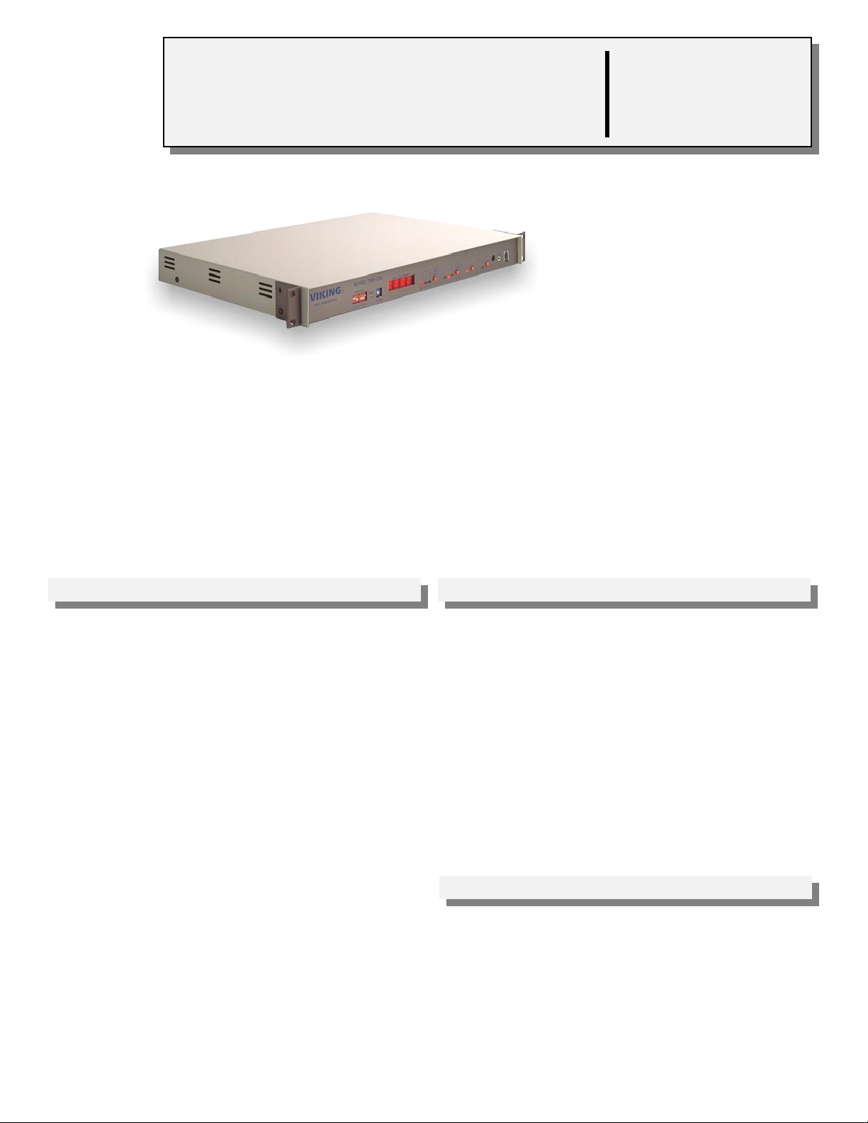
Answer up to 12 Lines
The TMS-12A Automatic Call
Sequencer will answer up to 12
inbound lines promptly with a clear,
digitally-recorded voice announcement informing the caller that their
call will be taken by the first
available representative. The call is then placed on
hold. In addition, two TMS-12A’s can be cascaded to
support up to 24 lines.
Optional music and/or promotional announcements will keep the caller assured that
their phone connection is intact and will be answered soon. A pacifier message can
also be recorded to confirm that the call will be answered.
Call statistics as well as the line number of the oldest holding call will be displayed on
the LED. In addition, an optional ring generator, SQRG-12, may be added to provide
complete sequencer automation.
cadgfdll
VIKING©
http://www.VikingElectronics.com
Features Applications
• Compatible with Electronic Key systems, 1A2 Key
systems and PABX systems
• Cascadable to support up to 24 lines
• Automatically change between day and night modes
via a contact closure, timer, remote switch or
remote programming
• Locally recordable with a standard carbon handset
or download announcements directly from a tape
player
• Remotely recordable
• Rechargeable battery back-up included
• Field expandable record time
• Separate recordings for each announcement
• Display for caller priority, inbound call statistics and
record time
• Inbound call statistics:
1. Total inbound calls
2. Total sequenced calls
3. Total abandoned calls
• 19” rack-mount hardware included
• “A” lead control for 1A2 Key Systems
• Console operator back-up (eliminates ring - no
answer)
• Multi-line barge-in announcer
• Multi-line remote dial-up access to audio sources
such as radio stations and public address systems
• Statistical tracking of inbound call handling
Sales...(715) 386 - 8861
Made in the U.S.A.
Specifications
Power: 120V AC/13.8V AC, 1.25A UL listed adaptor provided
Dimensions: 483mm x 305mm x 44mm (19” x 12” x 1.75”)
Shipping Weight: 3.4 kg (7.5 lbs)
Environmental: 0°C to 32°C (32°F to 90°F) with 5% to 95% non-
condensing humidity
Message Length: 32 seconds (expandable to 2 minutes using the
DRAM-1M)
Sampling Rate: 32 K
Battery Back-up: 2 hours minimum, 8 hours typical
Connections: (1) RJ21X female jack, (2) 3.5mm (1/8”) audio
jacks, (2) RJ11 jacks, (1) carbon handset jack
Page 2
Installation
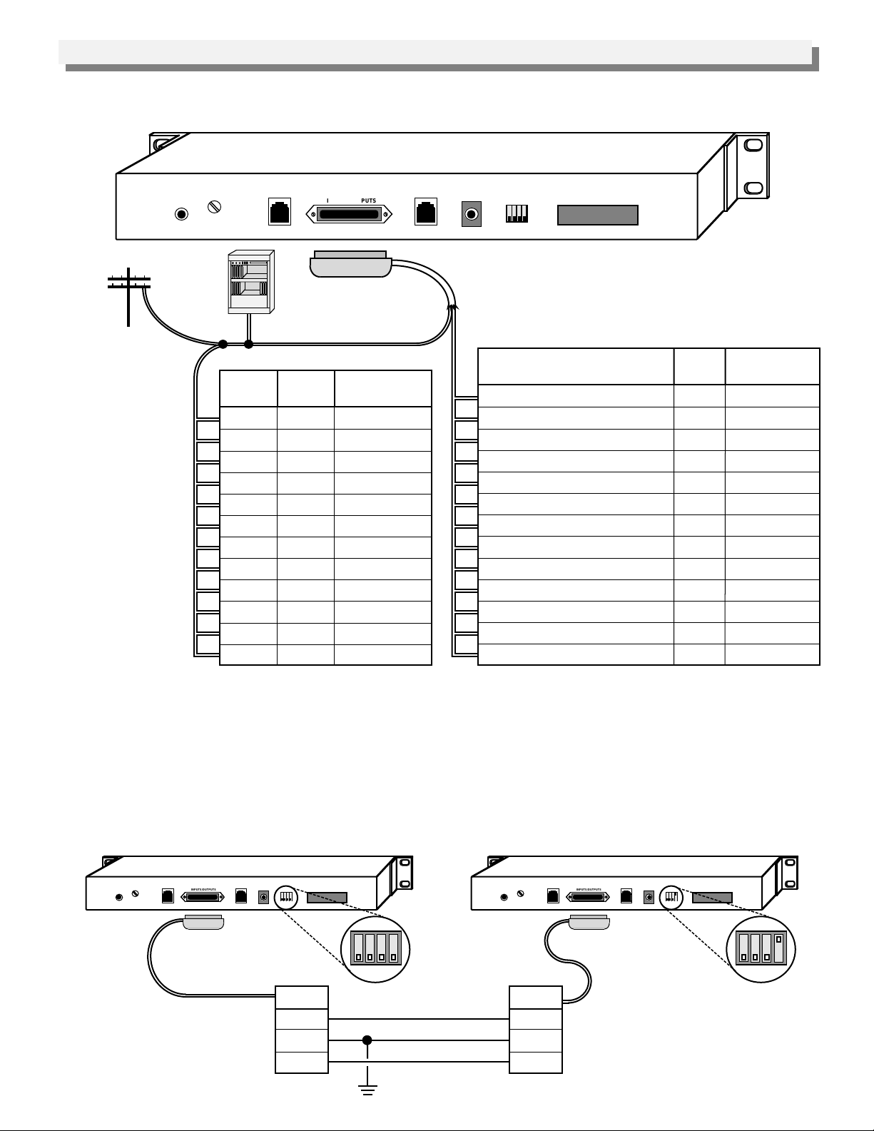
A. Telephone Wiring
The TMS-12A must be installed in parallel on 1 to 12 lines as shown below.
Rear panel of TMS-12A
USE ONLY
LISTED
CLASS 2
POWER
SOURCE
MUSIC
WARBLE
VOLUME
SQRG-12
TMS-RDMA
INPUTS/OUTPUTS
TMS-RDMA
9 10 11 12
Viking Electronics, Inc.
Hudson, WI 54016
C.O. line
PABX
KSU
Line
1
2
3
4
5
6
7
8
9
10
11
12
(not included)
Pins
26/1
27/2
28/3
29/4
30/5
31/6
32/7
33/8
34/9
35/10
36/11
37/12
RJ21 Male
Connector
Color
W-BL/BL-W
W-O/O-W
W-G/G-W
W-BN/BN-W
W-S/S-W
R-BL/BL-R
R-O/O-R
R-G/G-R
R-BN/BN-R
R-S/S-R
BK-BL/BL-BK
BK-O/O-BK
Additional Interfaces
“A” lead line 1/7
“A” lead line 2/8
“A” lead line 3/9
“A” lead line 4/10
“A” lead line 5/11
“A” lead line 6/12
Earth Gnd/”A” lead com
Com In/Com Out
SQRG-12 or TMS-RDMA (G/R)
SQRG-12 or TMS-RDMA (Y/B)
TMS-RDMA (W/B)
LM-24D/LM-24D Gnd
Day/Night (off) Mode select
Pins
38/13
39/14
40/15
41/16
42/17
43/18
44/19
45/20
46/21
47/22
48/23
49/24
50/25
Color
BK-GN/GN-BK
BK-BN/BN-BK
BK-S/S-BK
Y-BL/BL-Y
Y-O/O-Y
Y-G/G-Y
Y-BN/BN-Y
Y-S/S-Y
V-BL/BL-V
V-O/O-V
V-G/G-V
V-BN/BN-V
V-S/S-V
B. Master/Slave Wiring
Using an additional TMS-12A configured as a slave, up to 24 lines can be sequenced. In the master/slave
configuration, all recordings, statistics, remote access and answer protocols are handled independently between
master and slave.
To enable a TMS-12A to be a slave unit, set switch 12 to the up position, “SL” will be displayed on the display. The
slave lines will be displayed as lines 13 - 24 on the master TMS-12A, TMS-RDMA or the LM-24D. The pins shown
below must be tied together for master/slave operation.
TMS-12A Master Unit
SQRG-12
WARBLE
TMS-RDMA
VOLUME
MUSIC
INPUTS/OUTPUTS
Master Unit Pins
(Switch 12 DOWN position)
TMS-RDMA
USE ONLY
LISTED
CLASS 2
POWER
SOURCE
9 10 11 12
Pins
20
44
45
Viking Electronics, Inc.
Hudson, WI 54016
WARBLE
VOLUME
MUSIC
Pins
45
44
20
Earth Ground
TMS-12A Slave Unit
SQRG-12
TMS-RDMA
INPUTS/OUTPUTS
TMS-RDMA
Slave Unit Pins
(Switch 12 UP position)
USE ONLY
LISTED
CLASS 2
POWER
SOURCE
9 10 11 12
Viking Electronics, Inc.
Hudson, WI 54016
9 10 11 129 10 11 12
Page 3
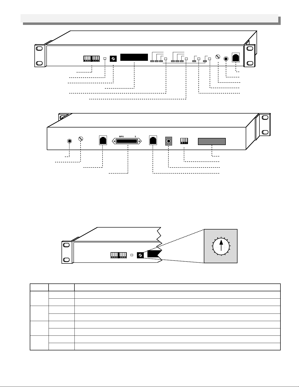
Diagram 1
Programming
Front Panel of the TMS-12A
VIKING©
CALL SEQUENCER
MODEL TMS-12A
PROTOCOL
1 2 3 4 5 6 7 8
RESET
Special Operating Modes
Processor/Data Reset
Security Code Select
Data/Line Priority/Record Time Display
NIGHT/DAY(3)/DAY(5)
OFF/RECORD/ANSWER Switch
Diagram 2
WARBLE
VOLUME
MUSIC
Music on Hold Input
Warble Volume
SQRG-12/TMS-RDMA Output
25 Pair line/Auxiliary Function Connector
SQRG-12
TMS-RDMA
A. Security Code
CODE
ABN ANS INB
NIGHT
DAY (3)
DAY (5)
DATA/LINE PRIORITY
0 0 0 0
Rear Panel of the TMS-12A
INPUTS/OUTPUTS
TMS-RDMA
USE ONLY
LISTED
CLASS 2
POWER
SOURCE
OFF
RECORD
ANSWER
9 10 11 12
START DATA
REC/MON
TAPE IN
VOL
Handset Jack
Tape In Jack
Playback Volume
Data Switch
Start/Stop Switch
Viking Electronics, Inc.
Hudson, WI 54016
Optional Comm Port
Special Operating Modes
13.8V AC Power Input
Second TMS-RDMA Output
The security code is used to gain access to remote programming and recording through line 12 only. To change the
security code, set the 16-position rotary CODE switch on the front of the unit to positions “1” through “9” only. This
will be your security code.
See sections D. Recording/Playback and E. Answer Protocols for more information on remote programming and
recording.
Front Panel of the TMS-12A
VIKING©
CALL SEQUENCER
MODEL TMS-12
PROTOCOL
1 2 3 4 5 6 7 8
RESET
DATA/LINE PRIORITY
0 0 0 0
CODE
4
5
3
2
1
0
F
6
7
8
9
E
A
B
D
C
B. PROTOCOL Switches (see front panel of the TMS-12A)
Switch
Position
Up
1
Down*
Up*
2
Down
Up
3
Down*
Up
4
Down*
Description
The ring delays are 1 and 2 in respect to the answer protocols (DAY(3) = 1, DAY(5) = 2, NIGHT = 1)
Normal ring delays (DAY(3) = 3, DAY(5) = 5, NIGHT = 3)
Only the oldest call will be released from the TMS-12A
The TMS-12A will release any call
The optional SQRG-12 will re-ring all lines being sequenced on the TMS-12A
The optional SQRG-12 will re-ring only the oldest line being sequenced on the TMS-12A
Lower fidelity announcements
Highest fidelity announcements
* = Default Setting
Continued...
Note: Whenever switch 3 is in the up position to re-ring all lines through the optional SQRG-12, switch 2 on the
TMS-12A front panel must be in the down position.
Page 4

...Continued
Switch
Position
Up
5
Down*
Up
6
Down*
Up
7
Down*
Up
8
Down*
Description
“Call Screening” mode. Calls are not displayed or re-rang until call has heard entire greeting message.
All calls are displayed in the sequence they ring in.
Unused
Normal operating position.
Optional auxiliary “off” operation.
Optional auxiliary “night” operation.
Optional auxiliary night/off operation is disabled.
Optional auxiliary night/off operation is enabled.
* = Default Setting
Note: When the auxiliary Night/Off mode is active, the front panel switches are disabled.
C. Special Operating Mode Switches (see rear panel of the TMS-12A)
Switch
9
10
11
12
Position
Up
Down*
Up
Down*
Up
Down*
Up
Down*
Description
“Barge-In” mode. All lines will be answered on the selected ring delay and will hear the greeting at any
point in the message, but will hear the entire message at least once.
Normal call sequencing.
Used with the TMS-STATS package (Fax Back Document 080).
Normal operating position.
Optional SQRG-12 ring generator mode is selected (Fax Back Document 060).
Optional TMS-RDMA remote display mode is selected (Fax Back Document 075).
Slave mode.
Master mode.
* = Default Setting
D. Recording/Playback
1. Local Recording
Note: All announcements must be recorded at the same time.
a. Plug a carbon handset into the REC/MON jack or plug a tape player into the TAPE IN jack (see Diagram 1).
b. Select the record mode by pressing OFF/RECORD/ANSWER switch until the LED indicates the record mode
(RECORD) is selected (see Diagram 1).
c. Select the announcement to be recorded (Greeting, Pacifier or Night) by pressing NIGHT/DAY(3)/DAY(5)
button until the LED indicates the desired announcement (see Diagram 1).
NIGHT - Night message
DAY(3) - Greeting message
DAY(5) - Pacifier message
d. Momentarily press the START switch and begin talking into the handset or press play on the tape player.
e. When finished recording, momentarily press the START switch.
f. Record the remaining announcements by repeating steps c - e.
Note: As the message is being recorded, the display will increment to show the amount of record time being
used. After a recording has been made, an “r” will appear in front of the record time for that message to show
that it has been recorded.
2. Local Playback
a. Set OFF/RECORD/ANSWER switch to off.
b. Set NIGHT/DAY(3)/DAY(5) switch to the desired message.
c. Momentarily press the START switch.
Page 5

3. Remote Recording
a. Call line 12 of the TMS-12A using a Touch Tone phone,
when the unit answers, enter a Q.
b. When the recording stops, enter “7” followed by the
security code (see Programming section A).
c. Enter a Touch Tone (1 - 3) to select an announcement to
record (see Keypad Diagram to the right).
d Begin recording your announcement.
e. Press # when finished.
f. Repeat steps c - e to record the other announcements.
g. Enter Q1 to exit the remote access mode.
Keypad
Diagram
Record
Playback
Select Mode
Pacifier On Hold Announcement
Answer Announcement
1 2 3
Night Announcement
4 5 6
7 8
9
h. Hang up and the TMS-12A will return to normal operation.
Notes: If you neglect to dial Q1 before hanging up from the remote mode, and the TMS-12A line 12 position is connected to
PABX extension or a loop start CO line that does not provide disconnect supervision (CPC), line 12 will not be released from
the TMS-12A for ten minutes after you have hung up. In the Off mode, the TMS-12A will still answer line 12 but will not play
the Greeting message.
4. Remote Playback
a. Call line 12 of the TMS-12A using a Touch Tone phone, when the unit answers, enter a Q.
b. When the recording stops, enter “7” followed by the security code (see Programming section A).
c. Enter a Touch Tone (4 - 6) to select an announcement to playback (see keypad diagram above).
d. The TMS-12A will playback the announcement.
e. Enter Q1 to exit the remote access mode.
f. Hang up and the TMS-12A will return to normal operation.
Notes: If you neglect to dial Q1 before hanging up from the remote mode, and the TMS-12A line 12 position is connected to
PABX extension or a loop start CO line that does not provide disconnect supervision (CPC), line 12 will not be released from
the TMS-12A for ten minutes after you have hung up. In the Off mode, the TMS-12A will still answer line 12 but will not play
the Greeting message.
E. Answer Protocols
1. Local Programming
a. Select the answer mode by pressing OFF/RECORD/ANSWER switch until the LED indicates the “Answer”
mode is selected.
b. Select the answer protocol by pressing NIGHT/DAY(3)/DAY(5) switch until the LED indicates the desired
protocol as described below.
1. NIGHT mode - Incoming calls will be answered on three rings, the night announcement will be played, and
then the call is released.
2. DAY(3) mode - Incoming calls will be answered on three rings, the answer announcement will be played
and then the call will be placed on hold.
3. DAY(5) mode - Incoming calls will be answered on five rings, the answer announcement will be played
and then the call will be placed on hold.
2. Remote Programming
a. Call line 12 of the TMS-12A using a Touch Tone phone, when the unit answers, enter a Q.
b. When the recording stops, enter “7” followed by the security code (see Programming section A).
c. Enter 7 for DAY(5), 8 for DAY(3) or 9 for NIGHT.
d. The TMS-12A will confirm your selection by playing the selected announcement.
e. Enter Q1 to exit the remote access mode.
f. Hang up and the TMS-12A will return to normal operation.
Notes: If switch 1 on the front panel of the TMS-12A is in the down position, the ring delays for Touch Tones 7 and 8 will be
5 and 3 respectively. If switch 1 is in the up position, these Touch Tones will set the ring delays to 2 and 1 respectively. If
you neglect to dial Q1 before hanging up from the remote mode, and the TMS-12A line 12 position is connected to PABX
extension or a loop start CO line that does not provide disconnect supervision (CPC), line 12 will not be released from the
TMS-12A until ten minutes after you have hung up. In the Off mode, the TMS-12A will still answer line 12 but will not play an
answering message.
Page 6

3. Automatic Night/Day Mode
The TMS-12A will change into the Night answer mode
(switch 7 down) or Off mode (switch 7 up) when 9 - 15 volts
AC or DC is applied across pins 25 and 50.
An “A” will be displayed and except for statistics, front
panel switches are disabled on the TMS-12A while in the
auxiliary Night/Off mode. See the diagram to the right.
a. Automatic Timer
For automatic Night/Off mode, add a programmable
timer (Radio Shack part # 61-1065 or equivalent) and a
9-15 volt AC or DC power supply. See the diagram to
the right.
b. Night Service Contact Closure
For a manual Night answer mode (switch 7 down) or Off
mode (switch 7 up), add a contact closure from the
PABX or a switch at the receptionist’s desk.
F. Turning the TMS-12A On or Off
1. Local Programming
Push the OFF/RECORD/ANSWER switch until the OFF, RECORD or ANSWER LED lights.
2. Remote Programming
a. Call line 12 of the TMS-12A using a Touch Tone phone, when the unit answers, enter a Q.
b. When the recording stops, enter “7” followed by the security code (see Programming section D).
c. Enter Q2 to place the TMS-12A in the Off mode.
d. Enter Q3 to place the TMS-12A in the On (“Answer”) mode.
e. Enter Q1 to exit the remote access mode.
f. Hang up and the TMS-12A will return to normal operation.
Notes: If you neglect to dial Q1 before hanging up from the remote mode, and the TMS-12A line 12 position is connected to
PABX extension or a loop start CO line that does not provide disconnect supervision (CPC), line 12 will not be released from
the TMS-12A until ten minutes after you have hung up. In the Off mode, the TMS-12A will still answer line 12 but will not play
an answering message.
AC Adapter Output
9V - 15V AC or DC
00
11111111::::333300
am
on off set
Programmable
on/off Timer
AC Adapter Output
9V - 15V AC or DC
Night Service
Contact Closure
or
Remote Switch
To TMS-12A 25
Pair Connector
Pin 50 (V/S)
Pin 25 (S/V)
To TMS-12A 25
Pair Connector
Pin 50 (V/S)
Pin 25 (S/V)
3. Automatic Off/On Mode
The TMS-12A will change into the Night answer mode
(switch 7 down) or Off mode (switch 7 up) when 9 - 15 volts
AC Adapter Output
9V - 15V AC or DC
AC or DC is applied across pins 25 and 50.
An “A” will be displayed and except for statistics, front
00
11111111::::333300
panel switches are disabled on the TMS-12A while in the
auxiliary Night/Off mode. See the diagram to the right.
a. Automatic Timer
For automatic Night/Off mode, add a programmable
timer (Radio Shack part # 61-1065 or equivalent) and a
9-15 volt AC or DC power supply. See the diagram to
the right.
b. Night Service Contact Closure
For a manual Night answer mode (switch 7 down) or Off
Programmable
AC Adapter Output
9V - 15V AC or DC
am
on off set
on/off Timer
Night Service
Contact Closure
or
Remote Switch
mode (switch 7 up), add a contact closure from the
PABX or a switch at the receptionist’s desk.
G. Common Audible
1. To eliminate confusion in key system applications, disable the ringer or program the attendant’s phone not to
ring. The TMS-12A will provide common audible if installed near the receptionist.
2. On incoming calls, the TMS-12A will provide a single warble tone every 4 seconds.
3. Once a line is answered by the TMS-12A, a double warble tone is provided.
4. Warble volume can be adjusted by the potentiometer (marked WARBLE) on the back panel of the TMS-12A.
To TMS-12A 25
Pair Connector
Pin 50 (V/S)
Pin 25 (S/V)
To TMS-12A 25
Pair Connector
Pin 50 (V/S)
Pin 25 (S/V)
Page 7

H. Playback Volume
To adjust the playback volume of messages, turn the potentiometer on the front of the unit (marked VOL) clockwise
to increase the volume or counter-clockwise to decrease the volume as shown below. This will change the volume
for all announcements.
Playback Volume
Front Panel of the TMS-12A
VIKING©
CALL SEQUENCER
MODEL TMS-12
PROTOCOL
RESET
1 2 3 4 5 6 7 8
CODE
DATA/LINE PRIORITY
0 0 0 0
ABN ANS INB
NIGHT
DAY (3)
DAY (5)
OFF
RECORD
ANSWER START DATA
REC/MON
TAPE IN
VOL
VOL
I. Expanding the Announcement Length
The TMS-12A ships with 32 seconds of high fidelity recording capability. Forty seven seconds of recording time is
possible at a lower fidelity by placing protocol switch 4 in the up position. A total of 2 minutes of high fidelity or 3
minutes of lower fidelity recording is possible with the addition of the Viking DRAM-1M (Fax Back Document 055)
memory expansion kit. For faster call processing, make your answer and pacifier announcements short.
Operation
A. Day Mode
In the DAY(3) or DAY(5) mode of operation, the TMS-12A will answer on the number of rings programmed (1, 2, 3
or 5) as explained in Programming, section B. This allows your receptionist to answer the phone first, if she is
available. After answering a call, the caller will hear the recorded greeting message. While this message is playing,
no other calls can be answered, but all calls that have met the ring delay will be answered as soon as the message
is finished. It is advisable to keep this message as short as possible. After the greeting has played, the caller is
placed on hold and the line that the oldest call is holding on will be displayed on the front panel of the TMS-12A or
on the optional TMS-RDMA remote display (see section D. Options, below). The call may then be released to the
receptionist by picking up that line.
released, the line that the next oldest call is holding on will be displayed.
Note: Only the oldest call may be released.
When the oldest call has been
While holding, and if recorded, a “Pacifier” message will be played approximately every 30 seconds.
If a call has been holding for longer than 4 seconds, the TMS-12A or TMS-RDMA will produce a double warble tone
audible signal (hold reminder tone) every 4 seconds.
B. Night Mode
In the NIGHT mode, the call will be answered after the programmed ring delay, the night message will be played
and the call will be disconnected.
C. Data Retrieval
In any mode of operation other than remote programming, statistics for Calls Abandoned, Calls Answered, and
Inbound Calls can be viewed.
1. Hold in the data switch, the display will show the current statistic total for the item highlighted by the LED (ABN,
ANS or INB).
2. To select the next statistic, momentarily release, then depress the data switch, and the next statistic item will be
highlighted.
3. The statistics can be reset to zero by depressing the reset button on the front panel of the TMS-12A.
Notes: This will reset the microprocessor and statistics only, the recorded messages will not be lost. However, any
calls holding in the TMS-12A will be dropped. This reset should only be done at a time when the TMS-12A is not
processing calls.
D. Troubleshooting
If the TMS-12A does not release the call to the key system or PABX, follow steps 1 - 3.
Note: This is usually
caused by high line current from the C.O. or PABX when the system is located close to a central office.
Page 8

1. Measure the voltage across tip and ring when the key system or PABX has seized the line. The voltage must be
less than 11 volts for the TMS-12A to recognize that the key system or PABX has gone off-hook and that it
should release the line.
2. If the voltage is greater than 11 volts, install (2) 150 ohm, 1/2 watt resistors (included) in series with both tip and
ring as shown below.
Rear View of the TMS-12A
SQRG-12
WARBLE
TMS-RDMA
VOLUME
MUSIC
INPUTS/OUTPUTS
TMS-RDMA
USE ONLY
LISTED
CLASS 2
POWER
SOURCE
9 10 11 12
Viking Electronics, Inc.
Hudson, WI 54016
Volt Meter
>11.0
150Ω 1/2W
Key System,
PABX/KSU
Important: Do not install
resistors in these locations:
Tip
Ring
150Ω 1/2W
To C.O. Line
10A
300mA
3. Recheck the voltage as shown above. If it is greater than 11 volts, contact Technical Support at (715) 386-8666.
Note: Have the voltage readings from before and after the resistors were installed available when calling
Technical Support.
Optional Equipment
A. Using the TMS-12A with the SQRG-12 Sequential Ring Generator
The SQRG-12 Sequential Ring Generator is designed for applications where more than
one person answers incoming calls, or in locations where the TMS-12A front panel
display is not visible. The SQRG-12 eliminates confusion about which line to answer
next by only ringing the oldest call to the key system or PABX.
In some applications it is desirable to have the SQRG-12 ring all calls that are ringing
lines or calls that are holding on the TMS-12A. This is required in many PABX
applications and some key system applications to prevent call crashing (glare) problems
when the C.O. lines connected to the TMS-12A are also used for outbound calls by the PABX or KSU. The SQRG-
12 is capable of this mode of operation when DIP switch 3 on the TMS-12A is in the on position (see Programming,
section B).
For more information on the SQRG-12, retrieve Fax Back Document 060.
when
B. Using the TMS-12A with Remote Displays
Remote displays allow the TMS-12A to be installed in the phone room rather
than on the receptionist’s desk. They will
than
display the line that the oldest call is holding
on and provide a common audible warble
while calls are holding.
For more information on the TMS-RDMA,
retrieve Fax Back Document 075.
For more information on the
LM-12W, retrieve Fax Back
Document 665.
For more information on
the LM-24D, retrieve Fax
Back Document 670.
C. Additional Call Statistics
As an upgrade package for the TMS-12A, the TMS-STATS allows the user to collect more detailed call activity
information. The kit includes both serial and parallel interface boards and a special ROM chip. The serial interface
board allows the TMS-12A to be connected directly to the serial port of a personal computer while the parallel
interface board is provided for interfacing with standard printers. For more information, retrieve Fax Back
Document 080.
Product Support Line...(715) 386-8666 Fax Back Line...(715) 386-4345
Due to the dynamic nature of the product design, the information contained in this document is subject to change without notice. Viking
Electronics, its affiliates and/or subsidiaries assume no responsibility for errors and/or omissions contained in this information. Revisions of
this document or new editions of it may be issued to incorporate such changes.
Printed in the U.S.A. ZF300190 Rev DFax Back Doc # 070
 Loading...