


TDR-1
TDR-1
Time Delay Relay
May 18, 2000
Viking's model TDR-1 is a time delay relay device
designed to be easily configured to fit a wide variety
of applications. The TDR-1 has (2) different modes
of operation:
1) In the Time Delay Mode, the TDR-1 can be programmed to produce one of 8 closure times. The
Trigger 1 input can be programmed to accept either
a dry contact closure or positive/negative going logic
level voltage.
2) The Delay on Operate mode delays an input trigger by a programmed interval. Eight delay times are
available, from 1 to 30 seconds.
Versatile Time Delay Relay
PPhhoonnee......771155..338866..8888661
1
iinnffoo@@vviikkiinnggeelleeccttrroonniiccss..ccoom
m
hhttttpp::////wwwwww..vviikkiinnggeelleeccttrroonniiccss..ccoom
m
• 1 Double Pole, Double Throw relay output
• 8 selectable closure times
• DIP switch programming
• Accepts positive or negative going logic
level voltage or contact closure
• Selectable time delay
• Screw terminal connections
• LED relay status indicator
• Controlled closure times
• Delayed closures
• Convert closures between N/O and N/C
Power: 120V AC to 12V DC adapter provided
Dimensions: 74mm x 53mm x 25mm (2.9” x 2.1” x 1.0”)
Shipping Weight: 0.4 kg (0.86 lbs)
Environmental: 0° C to 32° C (32° F to 90° F) with 5% to 95%
non-condensing humidity
Input: Logic level voltage (+ 5 VDC) or contact closure
Relay: 1A@30VDC, 0.3A@110 VDC, 0.5A@125VAC
Connections: 10 position cage clamp terminal strip
PPrraaccttiicce
e
T
T
EELLEECCOOM
M
S
S
OOLLUUTTIIOONNSSFFOORRTTHHE
E
221
1
SST
T
C
C
EENNTTUURRY
Y
TECHNICAL
TECHNICAL
AApppplliiccaattiioonns
s
FFeeaattuurrees
s
SSppeecciiffiiccaattiioonns
s
MMaaddeeiinntthheeUU..SS..AA.
.
A. Trigger Inputs
Referring to the diagram in Installation, section B, configure shunt JP1 to set up the trigger input for the proper input
polarity. For a positive going input, put the shunt on the (+) side. For a negative going input or dry contact closure,
leave the shunt on the (-) side (factory default).
IInnssttaallllaattiioon
n
PPrrooggrraammmmiinng
g
A. Mounting
1. Remove the cover from the TDR-1.
2. Mount the unit on a wall, using either screws or the included foam tape. Make
sure there is easy access to the internal terminal block. To facilitate mounting,
the internal board of the TDR-1 can be rotated exposing the two mounting holes
in the chassis.
3. Once mounted, swing the board back into position.
4. Wire unit as shown below.
5. Replace the cover, making sure the wires pass through the wiring cutout.
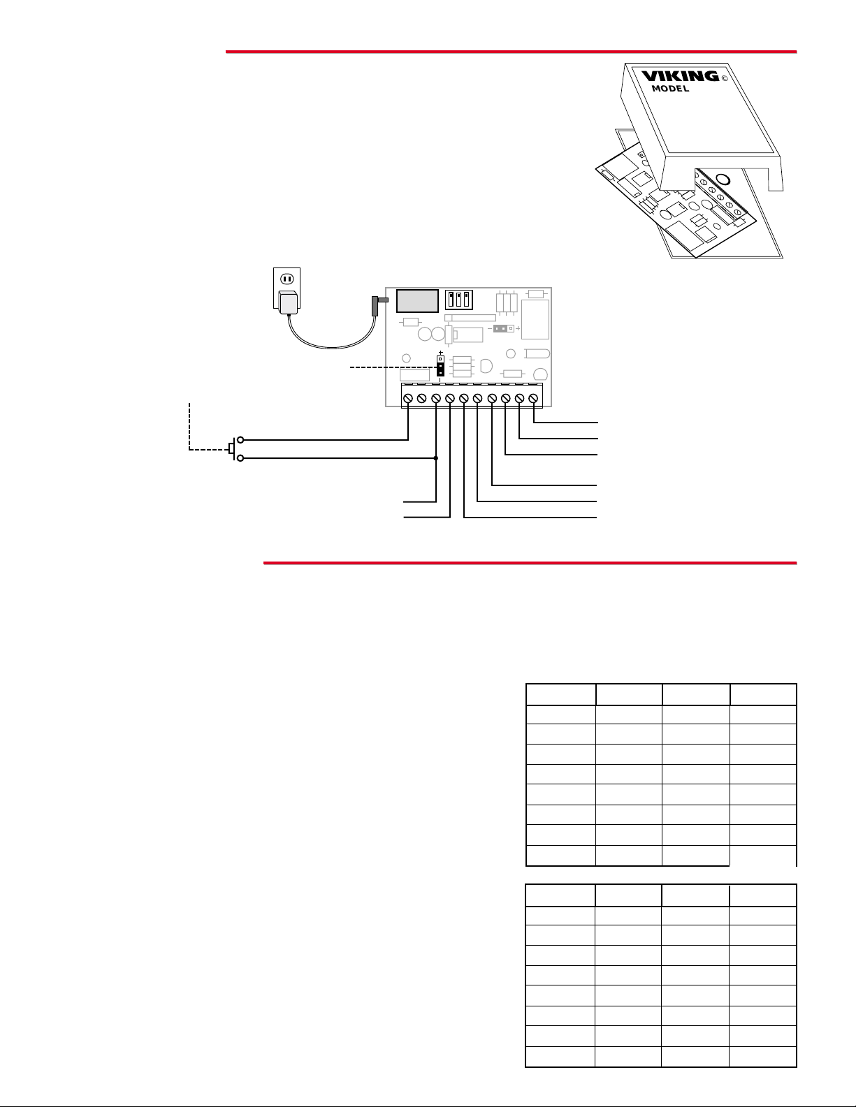
B. Wiring
VIKING
©
MODEL: TDR-1
321
Switch 1
OFF
OFF
OFF
OFF
ON
ON
ON
ON
Switch 2
OFF
OFF
ON
ON
OFF
OFF
ON
ON
Switch 3
OFF
ON
OFF
ON
OFF
ON
OFF
ON
Trigger 1
.5 sec
1 sec
2 sec
4 sec
7 sec
10 sec
15 sec
20 sec
C. Delay on Operate Mode
To put the TDR-1 into the “Delay on Operate Mode”, strap Trigger 2 to
ground by wiring terminal 2 to terminal 3. Refer to the diagram to the
right to set the dip switches for the desired delay time.
Note: See section “A. Trigger Inputs“ to set proper input polarity.
Switch 1
OFF
OFF
OFF
OFF
ON
ON
ON
ON
Switch 2
OFF
OFF
ON
ON
OFF
OFF
ON
ON
Switch 3
OFF
ON
OFF
ON
OFF
ON
OFF
ON
Trigger 1
1 sec
2 sec
4 sec
7 sec
10 sec
15 sec
20 sec
30 sec
Trigger 1
DC Common (GND)
JP1
(Trigger 1)
One Viking model PS-2 power supply
adapter can power up to (10) TDR-1s
by cascading screw terminals 3 and 4.
(GND)
12VDC In/Out
N/O
Common
N/C
N/O
Common
N/C
Momentary Contact
Closure or Logic
Level Voltage Input
120V DC Adapter
Provided
B. Time Delay Relay Mode
Choose the DIP switch setting for the desired activation time using the
diagram shown to the right.
Note: See section “A. Trigger Inputs“ to set proper input polarity.
1 234 567 8910
OFF
ON

OOppeerraattiioon
n
A. Trigger 1 Input
The Trigger 1 input can be set up to accept a contact closure to ground or to a positive/negative going logic level voltage. The trigger may be a momentary pulse or continuous trigger. If the trigger is held, it will not re-trigger the input
until it has been cleared. Examples are shown below.
B. Time Delay Relay Mode
When the TDR-1 receives a valid Trigger 1, the relay will activate for the programmed time. The TDR-1 does not look
at Trigger 1 again until the relay activation time is over.
Momentary Positive Going Trigger.
Momentary Negative Going Trigger
or Push Button to Ground.
Positive Trigger Held Continuous.
Negative Trigger or Push Button to
Ground Held Continuous.
* Denotes Trigger Starting Point
125 mS minimum
Trigger 1 Input
Relay Output
Active
Trigger 1
Activation Time
C. Delay on Operate Mode
The TDR-1 mimics any closure it sees at trigger 1, delayed by the amount of time programmed using the DIP switches as shown in Programming, section B.
Trigger 1 Input
Relay Output
Programmed
Delay Time
Programmed
Delay Time
*
Trigger A
Trigger B
Output A Output B
OOtthheerrCCoonnttaaccttCClloossuurreePPrroodduucctts
s
Contact Closure and Warble from a Ringing Line
The K-600D eliminates the installation of multiple bells, relays
and power supplies, whenever night bells, loud ringing or emergency tones are required. The K-600D provides an existing paging amplifier with a pleasant electronic warble tone each time it
receives ring voltage from a C.O. line or analog PABX/KSU
extension.
The K-600D requires no external power supply and provides a
floating 600 ohm audio output. Auxiliary N.O./N.C. relay contacts
are provided during ring signal for muting, switching or operation of external signaling devices. Volume
and tone controls are also provided. For more information on the K-600D, retrieve Fax Back
Document 475.
K-600D

Due to the dynamic nature of the product design, the information contained in this document is subject to change without notice. Viking Electronics, and its affiliates and/or
subsidiaries assume no responsibility for errors and omissions contained in this information. Revisions of this document or new editions of it may be issued to incorporate
such changes.
Fax Back Doc 421
ZF301410 Rev A
Printed in the U.S.A.
PPrroodduuccttSSuuppppoorrttLLiinnee......771155..338866..8866666
6
FFaaxxBBaacckkLLiinnee......771155..338866..4433445
5
Control Relay Contacts Remotely
The RC-2A Remote Controller provides single remote relay operation from any standard Touch Tone telephone. The controller is
designed to be installed either locally or remotely. For local installations the RC-2A can be installed in series on any analog line,
such as Viking’s Doorboxes.
For off-premise applications, the RC-2A can be installed on a line
shared by a key system, PABX, single line phone or on a dedicated line. The RC-2A will answer C.O. lines or analog PABX/KSU
station ports (after the programmable number of rings) and allow
remote relay operation. A field programmable security code may
also be programmed to prevent unauthorized usage. For more information, retrieve Fax Back
Document 160.
Control up to 3 Relay Contacts Remotely
The RC-3 Remote Controller provides remote relay operation for up
to 3 relays from any Touch Tone telephone. The controller is
designed to be installed either locally or remotely. For local installations the RC-3 can be installed in series on any analog line, such as
Viking’s Doorboxes.
For off-premise applications, the RC-3 can be installed on a line
shared by a key system, PABX, single line phone or on a dedicated
line. The RC-3 will answer C.O. lines or analog PABX/KSU station
ports (after programmable number of rings) and allow remote relay
operation . A field programmable security code can also be programmed to prevent unauthorized usage. Three RC-3's may be cascaded to provide up to 9 relay clo-
sures from a single line. For more information on the RC-3, retrieve Fax Back Document 165.
Loop and Ring Detect Relay Closure
The LDB-2 Ring/Loop Detector monitors an analog phone line for ringing
or an in-use condition. A built-in relay can be activated when either of these
conditions are detected. This is ideal for monitoring line status or for providing a visual indication of such.
When monitoring for ring, an internal pot can be adjusted to allow the relay
closure to stay on steady, or follow standard ring cadence.
The LDB-2 comes complete with a 12 VDC power adapter, and can also
provide 12V DC power through its auxiliary 12V DC output terminals. For
more information on the LDB-2, retrieve Fax Back Document 408.
RC-3
RC-2A
LDB-2
 Loading...