

Viking RVER33015BSS Installation
Installation
3 Series
Freestanding 30” Electric Self-Clean Range

2
Table of Contents
Warnings & Important Safety Instructions _______________________________________________3
Dimensions _________________________________________________________________________6
Specifications _______________________________________________________________________7
Clearance Dimensions (Proximity to Cabinets)___________________________________________8
Clearance Dimensions (Wood/Composite Overlay) ______________________________________9
Electrical Requirements _____________________________________________________________10
General Information ________________________________________________________________12
Installation_________________________________________________________________________13
Backguard Installation _______________________________________________________13
Door Removal ______________________________________________________________13
Leg Installation______________________________________________________________14
Electrical Connection (3-wire) _________________________________________________15
Electrical Connection (4-wire) _________________________________________________17
Leveling/Adjustments/Alignment ______________________________________________19
Anti-tip Device Installation____________________________________________________20
Wall Mount Anti-tip Installation _______________________________________________20
Floor Mount Anti-tip Installation_______________________________________________21
Final Installation_____________________________________________________________22
Door Replacement __________________________________________________________23
Final Preparation ___________________________________________________________________24
Performance Checklist ______________________________________________________________24
Service & Registration_______________________________________________________________25
IMPORTANT
3
• Before beginning, please read these
instructions completely and carefully.
• DO NOT remove permanently affixed
labels, warnings, or plates from product.
This may void the warranty.
• All local and national codes and ordinances
must be observed. Installation must
conform with local codes or in the absence
of codes, the National Fuel Gas Code
ANSIZ223.1/NFPA-54 – latest edition.
• The installer must leave these instructions
with the consumer who should retain for
local inspector’s use and for future reference.
In Canada: Installation must be in accordance
with the current CSA C22.1 Canadian
Electrical Codes Part 1 and/or local codes.
Your safety and the safety of others is
very important.
We have provided many important safety
messages in this manual and on your
appliance. ALWAYS read and obey all
safety messages.
This is the safety alert symbol. This
symbol alerts you to hazards that
can kill or hurt you and others.
All safety messages will be preceded by
the safety alert symbol and the word
“DANGER,” “WARNING” or “CAUTION.”
These words mean:
Hazards or unsafe practices
which WILL result in severe personal
injury or death
DANGER
Hazards or unsafe practices
which COULD result in severe personal
injury or death
Hazards or unsafe practices which
COULD result in minor personal injury or
property damage.
All safety messages will identify the
hazard, tell you how to reduce the chance
of injury, and tell you what can happen if
the instructions are not followed.
WARNING
CAUTION
–Read and Follow!
4
IMPORTANT–Read and Follow!
CAUTION
To prevent possible damage to cabinets
and cabinet finishes, use only materials
and finishes that will not discolor or
delaminate and will withstand
temperatures up to 194°F (90°C). Heat
resistant adhesive must be used if the
product is to be installed in laminated
cabinetry. Check with your builder or
cabinet supplier to make sure that the
materials meet these requirements.
A GFI
shall be used if required by NFPA-70 (National Electric Code), federal/state/local
laws, or local ordinances.
• The required use of a GFI is normally related to the location of a receptacle with respect to
any significant sources of water or moisture.
• Viking Range, LLC will NOT warranty any problems resulting from GFI outlets which are not
installed properly or do not meet the requirements below.
If the use of a GFI is required
, it should be:
• Of the receptacle type (breaker type or portable type NOT recommended)
• Used with permanent wiring only (temporary or portable wiring NOT recommended)
• On a dedicated circuit (no other receptacles, switches or loads in the circuit)
• Connected to a standard breaker of appropriate size (GFI breaker of the same size NOT
recommended)
• Rated for Class A (5 mA +/- 1 mA trip current) as per UL 943 standard
• In good condition and free from any loose-fitting gaskets (if applicable in outdoor situations)
• Protected from moisture (water, steam, high humidity) as much as reasonably possible
5
WARNING
ELECTRICAL SHOCK
HAZARD
To avoid risk of electrical shock,
personal injury or death; verify
your appliance has been properly
grounded in accordance with local codes
or in absence of codes, with the National
Electrical Code (NEC). ANSI/NFPA-70 –
latest edition.
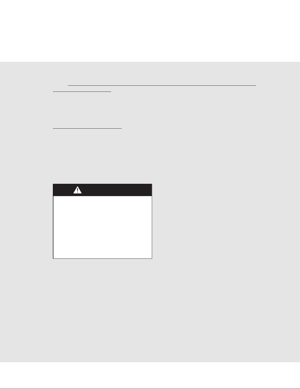
WARNING
MOVING HAZARD
To avoid risk of severe
personal injury; this appliance
requires two or more personnel while
handling and moving. Possible use of
appliance moving devices is recommended.
WARNING
TIPPING HAZARD
• THIS RANGE CAN TIP.
• A CHILD OR ADULT CAN
TIP THE RANGE AND BE
KILLED.
• FAILURE TO INSTALL THE
ANTI-TIP DEVICE CAN
RESULT IN DEATH OR
SERIOUS BURNS TO
CHILDREN OR ADULTS.
• IF THE RANGE IS MOVED THEN THE
ANTI-TIP DEVICE MUST BE
RE-ENGAGED.
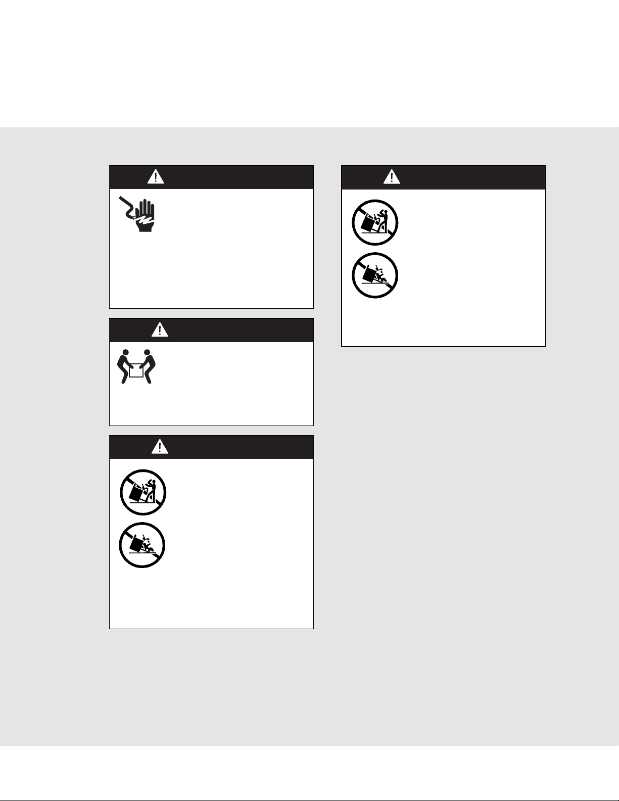
WARNING
TIPPING HAZARD
To reduce the risk of the
appliance tipping, it must be
secured by a properly installed
anti-tip bracket(s). To make
sure the bracket has been
installed properly, look behind
the range with a flashlight to
verify proper installation
engaged in the rear top left corner of the
range or under the range to verify that a floor
hook and bracket have been installed.
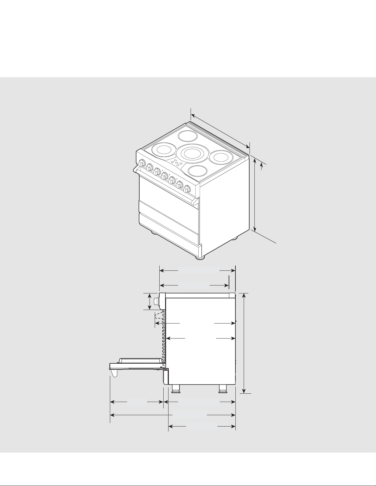
Dimensions
6
RVER/CRVER
Note: Unit shown with standard island trim
29-7/8”
(75.9 cm)
35-7/8”
(91.1 cm) min.
to
(94.0 cm) max.
37”
27-1/8” (68.9 cm)
25” (63.5 cm)
6”
(15.2 cm)
29” (73.7 cm)
25” (63.5 cm)
19-1/4”
(48.9 cm)
25-3/4” (65.4 cm)
45” (114.3 cm)
24” (61.0 cm)
35-7/8”
(91.1 cm) min.
to
37”
(94 cm) max.
Specifications
7
Electric 30” Range
Description
RVER/CRVER
Overall width
29-7/8” (75.9 cm)
Overall height To top of glass frame 35-7/8” (91.1 cm) min. to 37” (94.0 cm) max.
Legs adjust 1-1/8” (2.9 cm)
Overall depth from rear To end of side panel—25” (63.5 cm)
To front of door—25-3/4” (65.4 cm)
To front of control panel—27-1/8” (68.9 cm)
To end of knobs—29” (73.7 cm)
Additions to base
height
To top of island trim—add 0” (0.0 cm)
To top of backguard—add 6” (15.2 cm)
To top of high-shelf—add 18-3/16” (46.2 cm)
Electrical
requirements
240-208 VAC 60 Hz electrical connection box on product, connect with locally
supplied 3-wire, flexible cord or “pigtail” rated 40 amp. 125-250 VAC minimum.
Cord must be agency approved for use with household electric ranges.
Maximum wattage/amp
usage
240V—15,200 watts/63.3 amps
208V—11,400 watts/54.8 amps
Surface element rating
Left front
Left rear
Center
Right front
Right rear
2,000 watts
1,200 watts
3,200 watts
1,200 watts
2,000 watts
Oven interior width
25-5/16” (64.6 cm)
Oven interior height
16-1/2” (41.9 cm)
Oven interior depth
AHAM 16-13/16” (42.7 cm) Overall—19-1/2” (49.5 cm)
Oven volume Total oven capacity—4.7 cu. ft.
Measure to AHAM standards 4.1 cu. ft.
Approximate
shipping weight
426 lbs. (193.2 kg)
Note: Clearances from non-combustible materials are not part of the ANSI Z21.1 scope and not certified by
CSA. Clearances to non-combustible materials must be approved by the authority having jurisdiction.
Minimum clearances from adjacent combustible construction
• Cooking surface and below, i.e., 36” (91.4 cm) and below
o Sides—0”
• Above cooking surface, i.e. above 36" (91.4 cm)
o Sides—6” (15.2 cm)
o Within 6” (15.2 cm) side clearance, wall cabinets no deeper than 13” (33.0 cm) must be minimum 18” (45.7 cm)
above cooking surface.
o Wall cabinets directly above product must be minimum 36” (91.4 cm) for open top burners above cooking surface.
o Rear—0” with backguard or highshelf; 0” with island trim and noncombustible rear wall; 6” (15.2 cm) with island
trim and combustible rear wall.
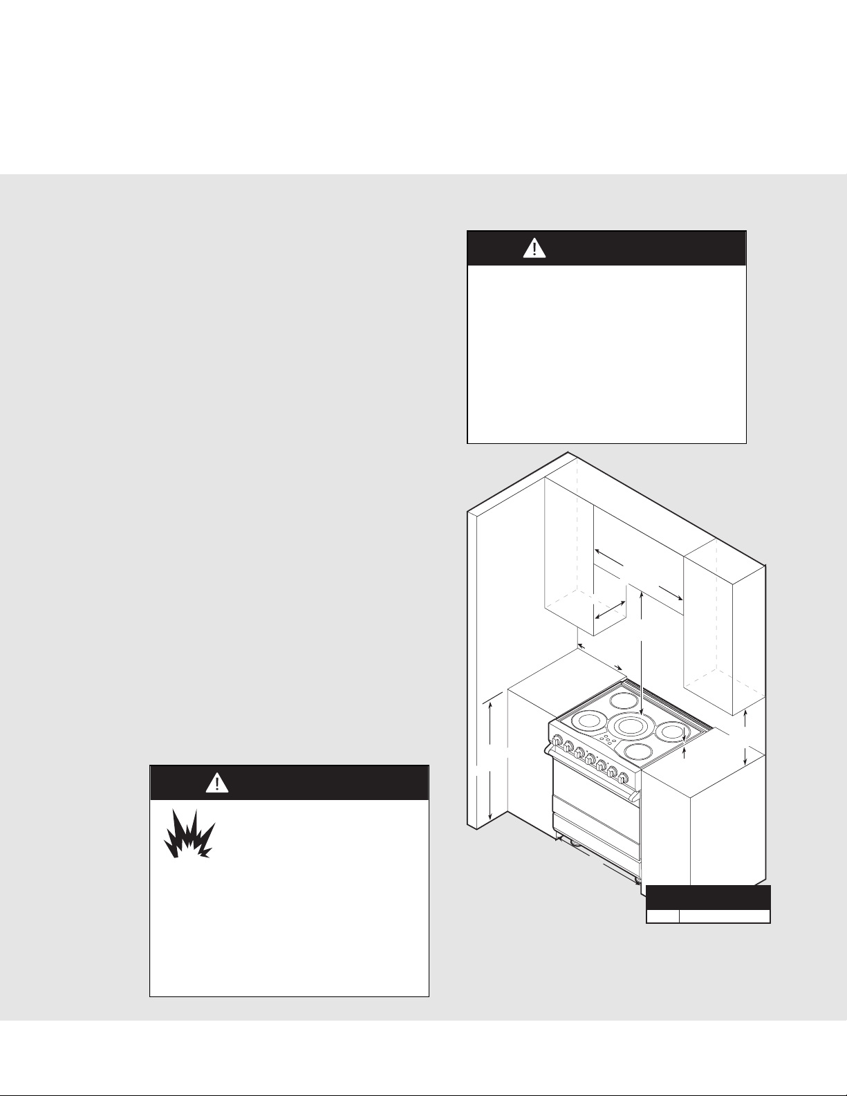
Clearance Dimensions (Proximity to Cabinets)
8
• This range may be installed directly adjacent
to existing 36” (91.4 cm) high base cabinets.
IMPORTANT: The side trim MUST be
3/8” (.95 cm) above the adjacent base
cabinet countertop. This can be
accomplished by raising the unit using
the adjustment spindles on the legs.
• The range CANNOT be installed directly
adjacent to sidewalls, tall cabinets, tall
appliances, or other side vertical surfaces
above 36” (91.4 cm) high. There must be
a minimum of 6” (15.2 cm) side clearance
from the range to such combustible surfaces
above the 36” (91.4 cm) counter height.
• Within the 6” (15.2 cm) side clearance to
combustible vertical surfaces above
36” (91.4 cm), the maximum wall cabinet
depth must be 13” (33.0 cm) and wall
cabinets within this 6” (15.2 cm) side
clearance must be 18” (45.7 cm) above
the 36” (91.4 cm) high countertop.
• Wall cabinets above the range must be a
minimum of 42” (106.7 cm) above the
range cooking surface for the full width
of the range. This minimum height
requirement does not apply if a range
hood is installed over the cooking surface.
Note: If a range hood is installed, wall cabinets above the
range have a different minimum clearance height.
CAUTION
BURN HAZARD
To avoid risk of personal injury;
the use of cabinets for storage
above the appliance may result
in a potential burn hazard. Combustible
items may ignite, metallic items may
become hot and cause burns. If cabinet
storage is used, the risk can be reduced
by installing a rangehood that projects
horizontally a minimum 5" (12.7 cm) beyond
the bottom of cabinets.
CAUTION
To prevent possible damage to cabinets
and cabinet finishes, use only materials
and finishes that will not discolor or
delaminate and will withstand temperatures
up to 194°F (90°C). Heat and moisture
resistant adhesive must be used if the
product is to be installed in laminated
cabinetry. Check with your builder or
cabinet supplier to make sure that the
materials meet these requirements.
29-7/8”
(75.9 cm)
13” max.
33.0 cm)
36”
91.4 cm)
(
(
6” min.
(15.2 cm)
42” min.
(106.7 cm)
(0.95 cm)
3/8”
8” min.
1
(45.7 cm)
A
Range
Width
30” 30” (76.2 cm)
“A”
Dimension
Clearance Dimensions (Wood/Composite Overlay)
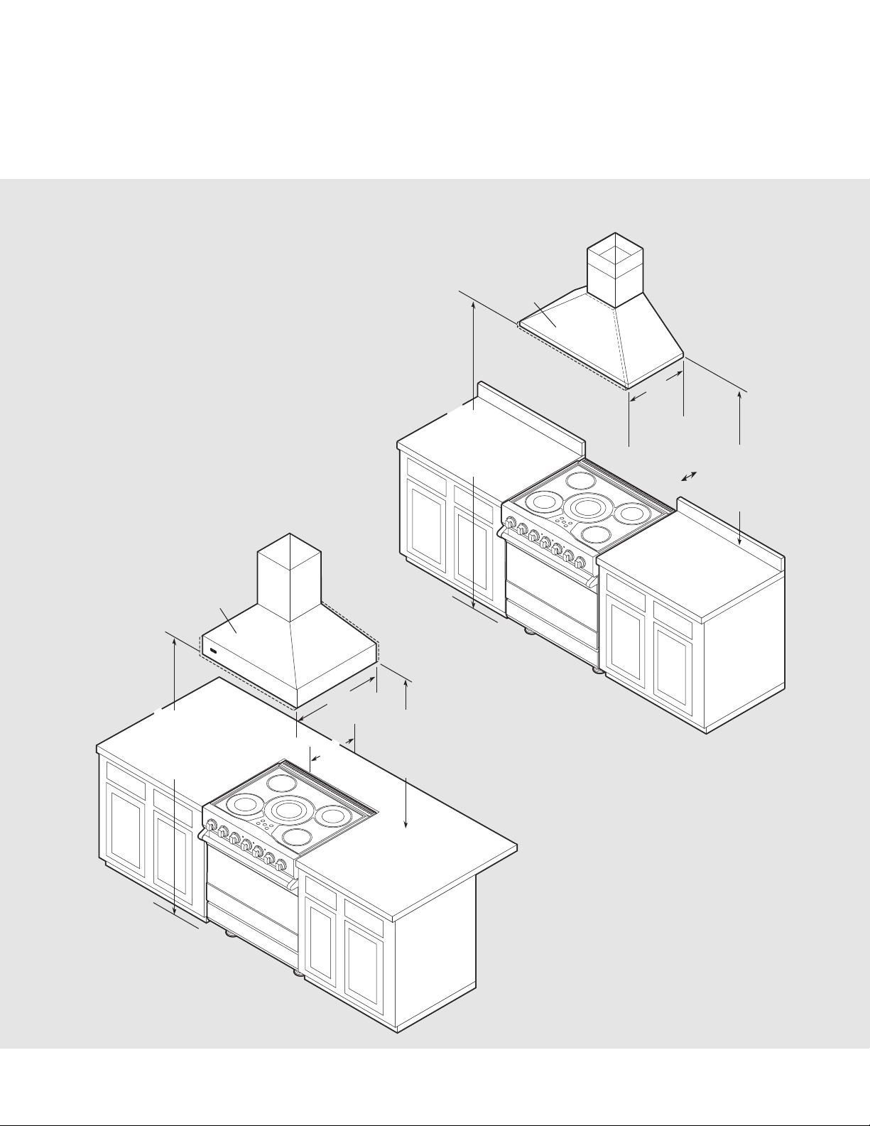
9
The bottom of a standard hood should be
30” (76.2 cm) min. to 36” (91.4 cm) max.
above the countertop. This would typically
result in the bottom of the hood being
66” (167.6 cm) to 72” (182.9 cm) above the
floor. Refer to the range hood installation
instructions for additional information. These
dimensions provide for safe and efficient
operation of the hood.
Wall Installation
Island Installation
Note: This range ships standard with an
island trim. There is a 6” (15.2 cm) min.
with island trim and combustible rear
wall. 0” with island trim and non-
combustible rear wall.
Note: Minimum clearance for back wall is
0” with backguard or high-shelf.
Note: Clearances from non-combustible
materials are not part of the ANSI Z21.1
scope and are not certified by CSA.
Clearances to non-combustible materials
must be approved by the authority having
jurisdiction.
Wood/Composite
Overlay
Wood/Composite
66”min.
(167.6 cm)
to
72”max.
(182.9 cm)
Overlay
24”
(61.0 cm)
or
27”
(38.6 cm)
0”
0 cm)
(
30”min.
(76.2 cm)
to
36”max.
(91.4 cm)
66”min.
(167.6 cm)
to
72”max.
(182.9 cm)
30”
(76.2 cm)
6”
(15.2 cm)
30”min.
(76.2 cm)
to
36”max.
(91.4 cm)
 Loading...