

Viking pi-150w Service Manual
PI-150W
PI-150W
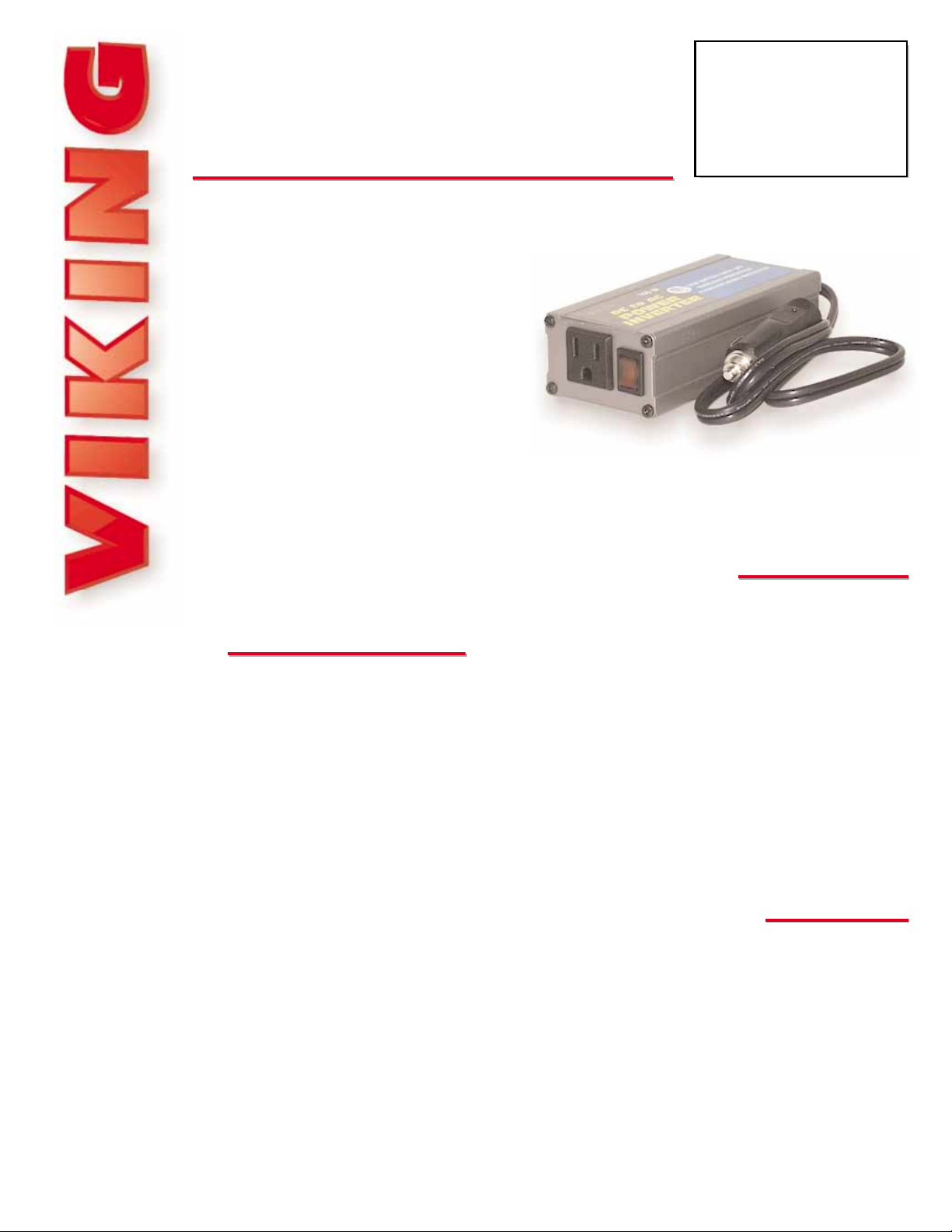
150W DC to AC
Power Inverter
March 2, 2000
The PI-150W converts 12 Volts DC to
115 Volts AC with a maximum continuous output power of 150 Watts. The PI-
150W will allow you to power Viking
products or other 1 15V AC equipment of
less than 150 watts from your vehicle,
boat, RV, solar panel or other available
12V DC source.
The PI-150W is equipped with a lighted power switch, power input fuse, low battery
alarm and low battery automatic shut down, allowing you to restart your vehicle as well
as preventing you from deep-cycling your battery.
Power your Viking products from 12V DC
PPhhoonnee......771155..338866..8888661
1
iinnffoo@@vviikkiinnggeelleeccttrroonniiccss..ccoom
m
hhttttpp::////wwwwww..vviikkiinnggeelleeccttrroonniiccss..ccoom
m
• 150 Watt continuous / 300 Watt surge output
power
• Male cigarette lighter plug
• Single power receptacle with ground
• Lighted output power switch
• Low battery voltage alarm
• Automatic low battery voltage shut down
• Automatic thermal overload shut down
• 30 Amp input fuse
• High efficiency/ low operating current
• 1 year limited warranty
• Powering Viking model DLE-200B or DLE-
300 for emergency or off site communica-
tions
• Powering Viking doorboxes from 12V DC
solar panels
• Powering any 115V AC equipment of less
than 150 watts from 11 to 15V DC
Dimensions: 145mm x 69mm x 41mm (5.7” x 2.7” x 1.6”)
Shipping Weight: 0.57 kg (1.25 lbs)
Environmental: -26° C to 54° C (-15° F to 130° F) with 5% to
95% non-condensing humidity
Maximum Current Draw with 12V Supply and 150 watt load:
Approximately 13 Amps
Input Voltage: 11 to 15V DC
Output Voltage: 115V AC RMS (modified sinewave)
Output Frequency: 60 Hz +/- 1 %
Output Power: 150 Watts continuous / 300 watts peak
No Load Current Draw: 200mA
Low Battery Alarm: 10.4V +/-0.5V DC
Low Battery Shut Down: 9.7V +/- 0.5 V DC
Efficiency: 90% at 75 Watts
DC Input Fuse: 30A
PPrraaccttiicce
e
T
T
EELLEECCOOM
M
S
S
OOLLUUTTIIOONNSSFFOORRTTHHE
E
221
1
SST
T
C
C
EENNTTUURRY
Y
TECHNICAL
TECHNICAL
AApppplliiccaattiioonns
s
FFeeaattuurrees
s
SSppeecciiffiiccaattiioonns
s
MMaaddeeiinntthheeUU..SS..AA.
.
Due to the dynamic nature of the product design, the information contained in this document is subject to change without notice. Viking Electronics, and its affiliates and/or
subsidiaries assume no responsibility for errors and omissions contained in this information. Revisions of this document or new editions of it may be issued to incorporate
such changes.
Fax Back Doc 507 ZF301460 Rev APrinted in the U.S.A.
PPrroodduuccttSSuuppppoorrttLLiinnee......771155..338866..8866666
6
FFaaxxBBaacckkLLiinnee......771155..338866..4433445
5
Note: For additional information please refer to the instruction manual supplied with the PI-150W, located in the bottom of
the plastic shipping package.
1. Connect the PI-150W to a DC power source between 1 1 and 15 volts which
is capable of supplying sufficient current to operate the load. Use this formula to calculate the current:
[Load Wattage ÷ DC Supply Voltage = Required current in Amps]
Example: The load is rated at 100 watts and the supply voltage is 12VDC.
100 watts ÷ 12VDC = 8.3 Amps required from the power source
The PI-150W may be connected directly to a 12V battery by using an
optional lighter socket with battery clips (Radio Shack part # 270-1527).
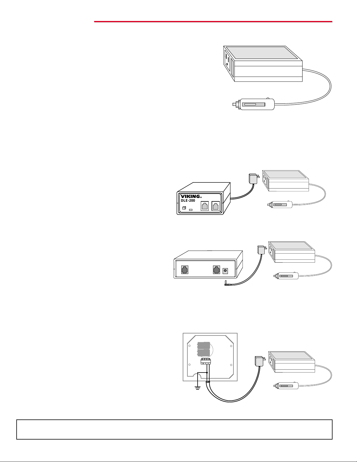
2. Turn on the power switch, which is located on the front of the inverter. The switch should illuminate indicating that the
PI-150W is in operation.
Important: Verify the 115V AC product you’re planning to power does not exceed 150 Watts then connect its power cord
to the AC receptacle on the front of the PI-150W. If the product you’re powering uses a power adapter it may interfere with
the inverters power switch, in which case an extension cord should be used.
C. Powering a Viking W-1000, W-2000A or W-3000 doorbox
Note: To eliminate any possible noise or hum on the doorbox. Connect
pin 3 of the terminal block to earth ground or chassis ground if used in
a mobile vehicle (see diagram below).
IInnssttaallllaattiioon
n
A. Powering a DLE-200B
B. Powering a DLE-300
VIKING©
DLE-200B
RES
RINGDOWN
BUSY
1
2
1 2 3 4
To 11-15V DC
Source
Viking's DLE-200B Line Simulator provides two way
communication between standard telecom products
such as modems, fax machines, key systems, PBX's,
and standard single line phones.
For more information on the DLE-200B, retrieve Fax
Back Document 605.
The DLE-300 Advance Line Simulator provides sales
people, technicians, engineers, etc., with a cost effective and easy to use method of conducting on-site
demonstrations, programming or diagnostics without
the need to locate phone lines or disrupt customer
phone service.
For more information on the DLE-300, retrieve Fax
Back Document 607.
The W-1000 (flush mount) and W-2000A (surface
mount) doorboxes are designed to be installed on
the unused telephone line input of nearly any phone
system. One or two doorboxes can also share an
existing residential phone line when used in combination with a C-1000 doorbox controller. For a
stainless steel doorbox with even more features,
use the W-3000.
For more information on the W-1000/2000A,
retrieve Fax Back Document 170. For more infor-
mation on the W-3000, retrieve Fax Back
Document 180.
USE ONLY LISTED
CLASS 2 POWER
SOURCE 13.8V
1.25 A MAX.
DEV 2DEV 1
Viking Electronics, Inc., Hudson, WI 54016
Rear View of the DLE-300
Rear View of the W-1000
PI-150W
PI-150W
PI-150W
DLE-200B
To 11-15V DC
Source
To 11-15V DC
Source
Earth Ground or
Chassis Ground
of Vehicle
 Loading...