

Page 1

Viking Range Corporation
111 Front Street
Greenwood, Mississippi 38930 USA
(662) 455-1200
For product information,
call 1-888-VIKING1 (845-4641)
or visit the Viking Web site at
vikingrange.com
F20661 EN
(041609J)
Viking Installation Guide
PHKDFSB5/PHKDFBB
Professional Series Handle Kit
For Use with DFSB5, DFBB5 and DFBB Built-In Full Overlay Refrigerators
Page 2
IMPORTANT–Please Read and Follow!
2 3
• Before beginning, please read these instructions completely and carefully.
• Use caution during assembly to minimize scratches.
• Do not remove permanently affixed labels, warnings or plates from the product. This may
void the warranty.
• Please refer to the DFSB5, DFBB5 or DFBB Installation Instructions for more information on
installing the refrigerator door panel.
• The installer should leave instructions with the customer who should retain for local
inspector’s use and future reference.
Parts Included
Part Quantity
Professional Series Handle Tubes
Professional Series End Caps
1/4” x 1” Phillips Head Screws
Installation Instructions
Required Tools
Electric Drill
5/16” (.8 cm) Drill Bit
5/8” (1.6 cm) Spade or Forstner Bit (Counterbore)
Tape Measure
Phillips Head Screwdriver
Masking Tape and Pencil
Rubber Mallet
Handle Installation
To Install:
Installation with Wooden Full Overlay
Custom Door Front
(2)
(4)
(8)
1. Locate the wooden custom panel.
2. Using the illustrations on the next page, layout the handle location on the panels. It is
recommended that masking tape be placed where the four holes will be drilled to help mark
the hole placement and to prevent any damage to the door when drilling the holes.
3. Each Professional Series handle will be mounted using (4) of the 1/4” x 1” Phillips head
screws provided. Using the 5/16”(.8 cm) drill bit, drill completely through the door in the
hole locations. Using the 5/8” (1.6 cm) bit, counter-bore two holes 1/4” (.6 cm) deep on the
BACKSIDE of the custom door panel.
4. Place a handle end cap on both ends of the handle tube. Tap the endcaps firmly into place
with a rubber mallet ensuring that both endcaps mounting surfaces are parallel.
5. Align the holes in the endcaps with the holes on the panel and attach the Professional
handle to the panel using the (4) 1/4” (.6cm) screws provided.
6. Repeat steps 1 - 4 to attach other handle.
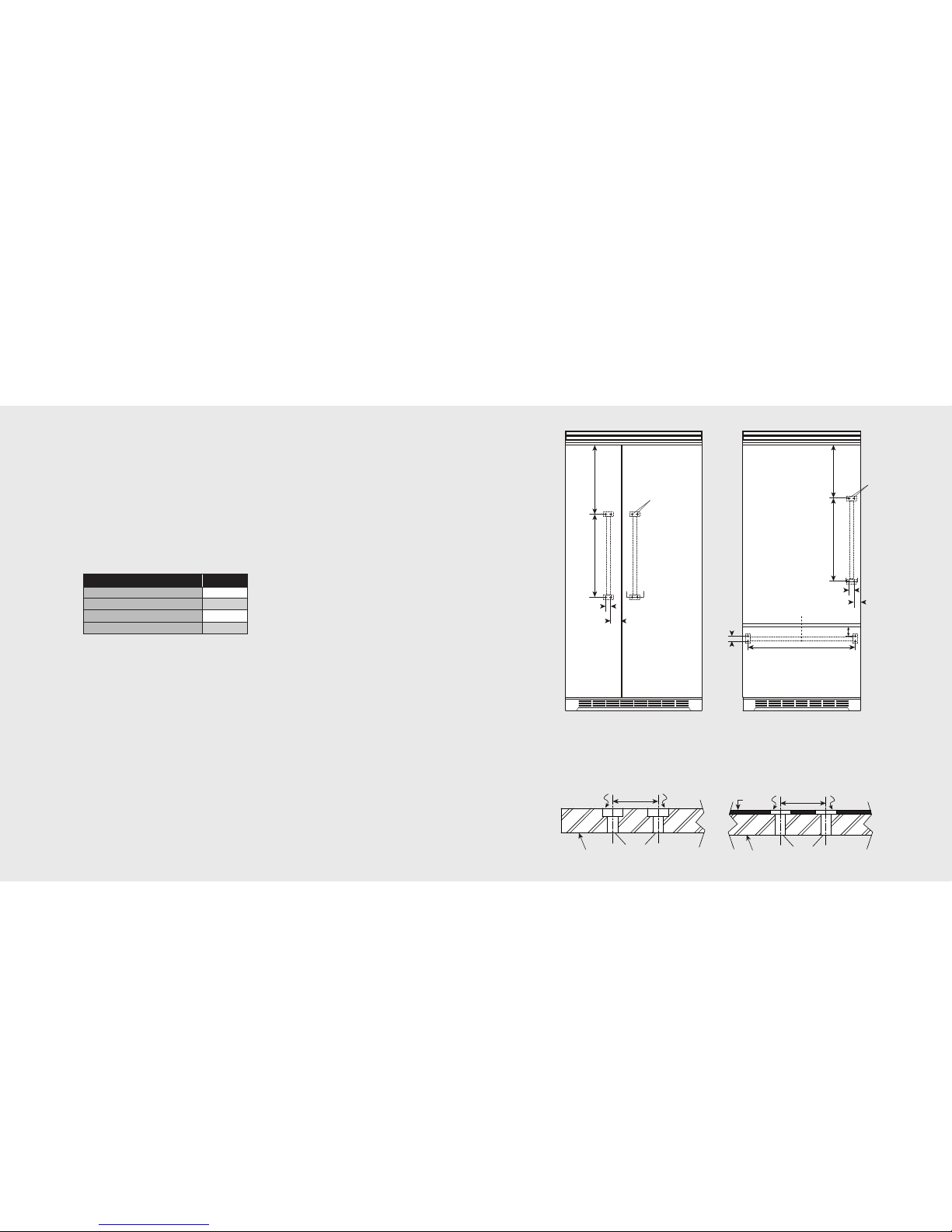
Custom Door
DFSB5 Side-by-Side (Front View)
Professional Series Handle
Specifications subject to change without notice.
17-15/16”
(45.6 cm)
27-1/2”
(
69.9 cm)
1-3/8”
(3.5 cm)
1-9/16”
(4.0 cm)
AA
5/16” (.8 cm)
t
hrough-holes
w
ith 5/8” x 1/4”
counterbore
*See section A-A.
5/8” (1.6 cm) Ø x 1/4” (.6 cm) counterbore
1-3/8” (3.5 cm)
5/16” (.8 cm) Ø through-holes
3/4” (1.8 cm)
Full Overlay Panel
Section A-A
Professional Series Handle
(Applies to DFSB5/DFBB5 Only)
Custom Door
DFBB5/DFBB Bottom Mount (Front View)
Professional Series Handle
9
”
(22.9 cm)
3
4-11/16”
(
88.1 cm)
1-3/8” (3.5 cm)
1-9/16” (4.0 cm)
AA
5/16” (.8 cm)
through-holes
with 5/8” x 1/4”
counterbore
*
See section A-A.
31-11/16” (80.5 cm)
1-9/16” (4.0 cm)
1-3/8”
(3.5 cm)
C
L
Section A-A
Professional Series Handle
5/8” (1.6 cm) Ø x 1/4” (.6 cm) counterbore
1-3/8” (3.5 cm)
5/16” (.8 cm) Ø through-holes
3/4” (1.8 cm)
Full Overlay Panel
1/4” (.6 cm)
Base Panel
 Loading...