

Page 1
Telecommunication Peripheral Products
Technical Practice
PF-6A
Power Fail Bypass
or Ground to
Loop Start Converter
March 23, 2000
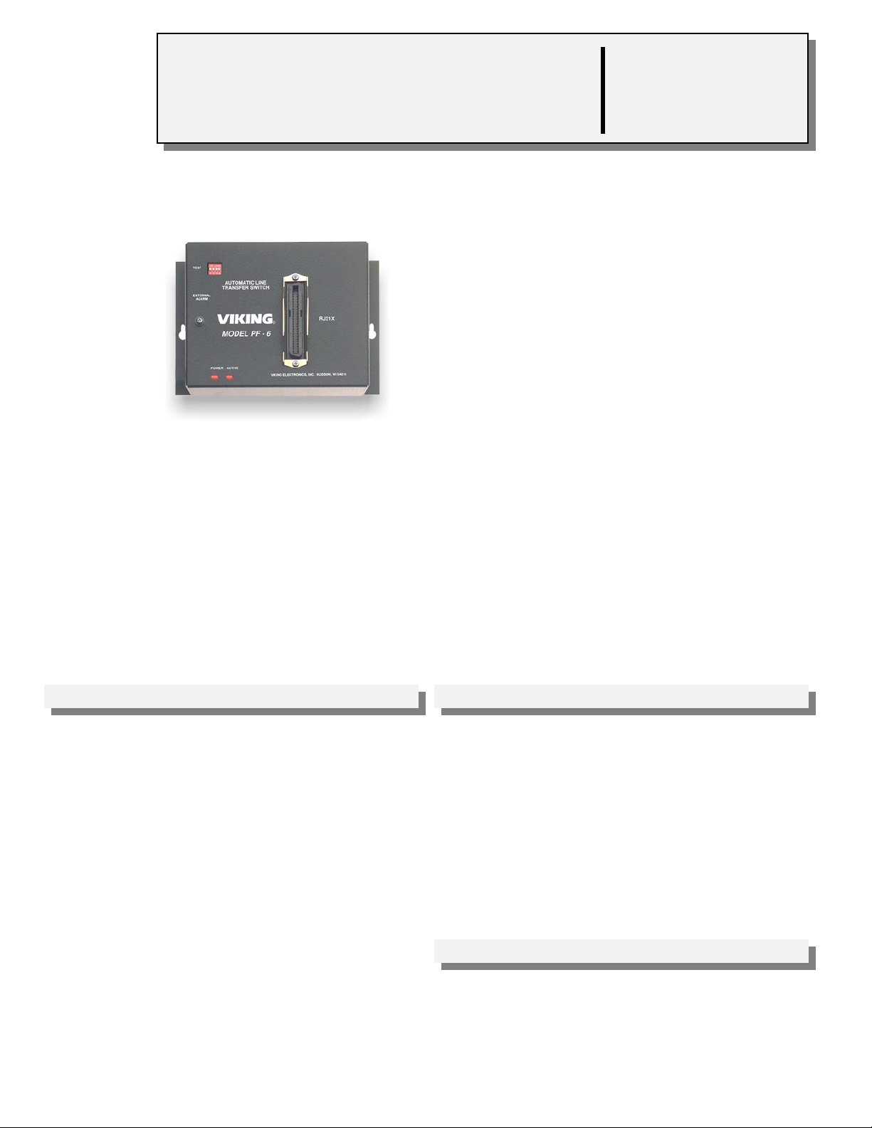
Power Failure Bypass System
With the PF-6A, you will continue to receive your
calls, during phone system and power outages. The
PF-6A bypass unit connects 6 preassigned single
line station phones directly to the C.O. trunks you
have assigned. A built in ground start converter
permits outbound calls from standard phones.
When the system is restored, you will not lose calls.
Viking’s PF-6A bypass unit will reconnect phones to
their station circuits after they become idle.
The PF-6A can be configured to operate when power is lost or from an opening/closing
of an alarm contact or manual closure.
The PF-6A can also be used to convert six incoming ground start lines to loop start
lines. This accommodates installation of telephony equipment requiring loop start lines
(i.e: key systems, call sequencers, answering machines, voice mail, etc.).
VIKING©
http://www.VikingElectronics.com
E-mail...Sales@VikingElectronics.com
Features Applications
• Transfers six C.O. trunks directly to the
designated analog station phones
• Stackable to increase capacity
• Allows you to receive calls as well as make
calls during power or system failure
• Compatible with loop start lines or 48V ground
start lines
• Prevents busy signals or unanswered calls
during power and system failures
• Converts ground start lines to standard loop
start lines
Sales...(715) 386 - 8861
Made in the U.S.A.
• Automatic ground start converter eliminates
“ground start buttons”
• Power restoration will not interrupt calls in
progress
• Operates on power failure or normally open normally closed alarm contacts
Specifications
Power: 120 V AC/13.8V AC 1.25A, UL listed adapter provided or
24-48V DC, 100mA
Dimensions: 187mm x 127mm x 45mm (7.35” x 5” x 1.75”)
Shipping Weight: .91 kg (2 lbs)
Environmental: 0°C to 32°C (32°F to 90°F) with 5% to 95% non-
condensing humidity
Connections: (1) RJ21X, (1) RJ11
Page 2
Normally Open
Contact Input
Installation
1 2 3 4
TEST
AUTOMATIC LINE
TRANSFER SWITCH
EXTERNAL
ALARM
VIKING©
MODEL PF-6A
RJ21X
Test Button
Dip Switches
POWER ACTIVE
VIKING ELECTRONICS, INC. HUDSON, WI 54016
Note: The unit can also be powered
by 24-48V DC PABX battery supply on
terminals 50 and 25.
POWER and ACTIVE LED - The POWER LED and the ACTIVE LED
will be lit when the PF-6A is in the normal operating mode. The
ACTIVE LED will go out and the POWER LED will stay lit when the test
button is pressed.
RJ21X Female Connector
Important: This unit is not protected against damage from power line surges. A surge protector is recommended if
operated on 120V AC.
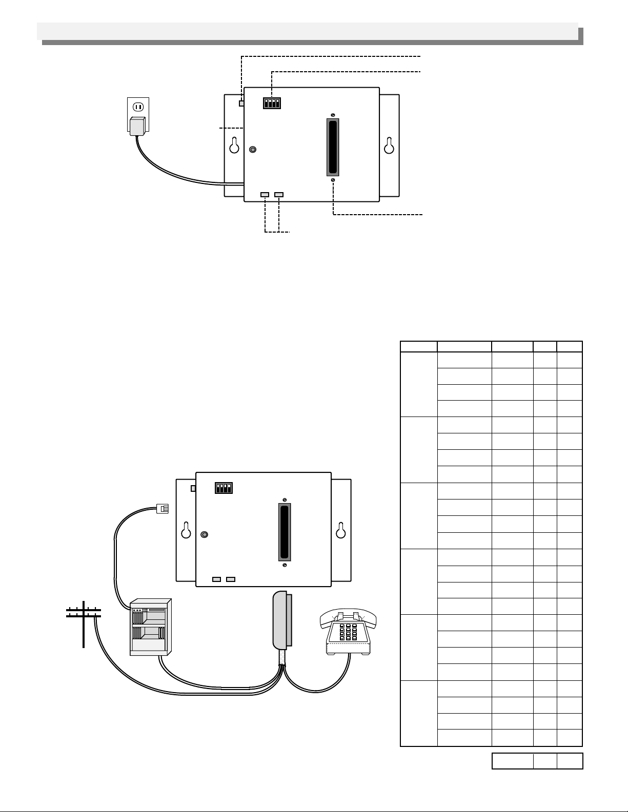
A. Power Fail Bypass Unit
It is recommended that the first six C.O. lines be interfaced with the
PF-6A as shown in the chart to the right.
If your system has an alarm contact or manual transfer switch, you
must connect it to the red and green wires of the modular jack labeled
EXTERNAL ALARM on the left side of the PF-6A. This must be a
normally open maintained contact closure. If normally closed alarm
contacts are used, wire them to break the power to the PF-6A when
they open.
Normally Open
Maintained
Contact Input
PABX/KSUC.O. Line
1 2 3 4
TEST
AUTOMATIC LINE
TRANSFER SWITCH
EXTERNAL
ALARM
VIKING©
MODEL PF-6A
POWER ACTIVE
RJ21X Male
(not included)
RJ21X
VIKING ELECTRONICS, INC. HUDSON, WI 54016
Connector
Note: Loop start and ground start CO lines may be combined on the
PF-6A (see Programming). When ground start lines are used, pin 50
(V/S) must be connected to a good earth ground.
Circuit
Circuit 1
Circuit 2
Circuit 3
Circuit 4
Circuit 5
Circuit 6
Station or trunk
Trunk 1 - IN
Trunk 1 - OUT
Station 1 - IN
Station 1 - OUT
Trunk 2 - IN
Trunk 2 - OUT
Station 2 - IN
Station 2 - OUT
Trunk 3 - IN
Trunk 3 - OUT
Station 3 - IN
Station 3 - OUT
Trunk 4 - IN
Trunk 4 - OUT
Station 4 - IN
Station 4 - OUT
Trunk 5 - IN
Trunk 5 - OUT
Station 5 - IN
Station 5 - OUT
Trunk 6 - IN
Trunk 6 - OUT
Station 6 - IN
Station 6 - OUT
control line
Line Pins ColorTrunk/station
T1T-IN
T1R-IN
T1T-OUT
T1R-OUT
S1T-IN
S1R-IN
S1T-OUT
S1R-OUT
T2T-IN
T2R-IN
T2T-OUT
T2R-OUT
S2T-IN
S2R-IN
S2T-OUT
S2R-OUT
T3T-IN
T3R-IN
T3T-OUT
T3R-OUT
S3T-IN
S3R-IN
S3T-OUT
S3R-OUT
T4T-IN
T4R-IN
T4T-OUT
T4R-OUT
S4T-IN
S4R-IN
S4T-OUT
S4R-OUT
T5T-IN
T5R-IN
T5T-OUT
T5R-OUT
S5T-IN
S5R-IN
S5T-OUT
S5R-OUT
T6T-IN
T6R-IN
T6T-OUT
T6R-OUT
S6T-IN
S6R-IN
S6T-OUT
S6R-OUT
GND
-24/48V5025
26
W/BL
1
BL/W
27
W/O
2
O/W
28
W/G
3
G/W
29
W/BN
4
BN/W
30
W/S
5
S/W
31
R/BL
6
BL/R
32
R/O
7
O/R
33
R/G
8
G/R
34
R/BN
9
BN/R
35
R/S
10
S/R
36
BK/BL
11
BL/BK
37
BK/O
12
O/BK
38
BK/G
13
G/BK
39
BK/BN
14
BN/BK
40
BK/S
15
S/BK
41
Y/BL
16
BL/Y
42
Y/O
17
O/Y
43
Y/GN
18
GN/Y
44
Y/BN
19
BN/Y
45
Y/S
20
S/Y
46
V/BL
21
BL/V
47
V/O
22
O/V
48
V/GN
23
GN/V
49
V/BN
24
BN/V
V/S
S/V
Page 3

B. Ground to Loop Start Converter
T
The ground start converter in the PF-6A will only work properly when connected in series with
the ground start trunks as shown below.
Note: The C.O. lines must be connected in
the correct polarity.
Line Pins Color
+
T1T-IN
-
T1R-IN
+
T2T-IN
-
T2R-IN
+
T3T-IN
-
T3R-IN
+
T4T-IN
-
T4R-IN
+
T5T-IN
-
T5R-IN
+
T6T-IN
-
T6R-IN
GND 50
26
1
30
34
9
38
13
42
17
46
21
Line
W/BL
BL/W
W/S
S/W
5
R/BN
BN/R
BK/G
G/BK
Y/O
O/Y
V/BL
BL/V
S1T-OUT
S1R-OUT
S2T-OUT
S2R-OUT
S3T-OUT
S3R-OUT
S4T-OUT
S4R-OUT
S5T-OUT
S5R-OUT
S6T-OUT
S6R-OUT
Pins Color
29
W/BN
4
BN/W
33
R/G
8
G/R
37
BK/O
12
O/BK
41
Y/BL
16
BL/Y
45
Y/S
20
S/Y
V/BN
49
BN/V
24
V/S
C.O.
Lines
Incoming
Ground Start
Trunks
Tip
1
Ring
Tip
2
Ring
Tip
3
Ring
Tip
4
Ring
Tip
5
Ring
Tip
6
Ring
Loop Start
Lines Out
Tip
Ring
Tip
Ring
Tip
Ring
Tip
Ring
Tip
Ring
Tip
Ring
PABX/KSU
1
2
3
4
5
6
1 2 3 4
TEST
AUTOMATIC LINE
TRANSFER SWITCH
EXTERNAL
ALARM
VIKING©
MODEL PF-6A
POWER ACTIVE
RJ21X
VIKING ELECTRONICS, INC. HUDSON, WI 54016
EARTH GROUND (V/S)
Important: Pin 50 must be connected to a
good earth ground for the PF-6A to function
properly with ground start lines.
Important: Do NO
connect the power
adapter when using the
PF-6A in the Ground to
Loop Start application.
RJ21X Male
Connector
(not included)
Programming
The DIP switches may be used to program loop start or ground start lines. You may also use DIP switch 1 to toggle
between normal and bypass mode for testing purposes.
1 2 3 4
TEST
AUTOMATIC LINE
TRANSFER SWITCH
EXTERNAL
ALARM
VIKING©
MODEL PF-6A
POWER ACTIVE
RJ21X
VIKING ELECTRONICS, INC. HUDSON, WI 54016
Dip Switch ON/OFF
1
OFF
ON
2
OFF
ON
3
OFF
ON
4
OFF
ON
Description
Normal operation
Bypass mode for testing
Assigns lines 1, 2, 3 to loop start
Assigns lines 1, 2, 3 to ground start
Assigns lines 4, 5, 6 to loop start
Assigns lines 4, 5, 6 to ground start
Not used
Not used
Page 4

Operation
A. Power Fail or System Fail Bypass
DIP Switches
After installation is complete, test the PF-6A by doing
one of the following:
1. Press and hold the TEST button
2. Move DIP switch 1 to the ON position
3. Disconnect power to the PF-6A
4. Provide a maintained normally open contact closure to
the EXTERNAL ALARM input
Maintained
Normally Open
Contact Closure
After installing and testing the PF-6A, instruct office personnel that in the event of the power failure or system failure
that the six assigned telephones will be the only means to receive and place calls.
While the PF-6A is in normal operating mode, the six C.O. lines are connected to the trunk inputs and the six
assigned station circuits are connected to their six telephones.
TEST Button
1 2 3 4
TEST
AUTOMATIC LINE
TRANSFER SWITCH
EXTERNAL
ALARM
VIKING©
MODEL PF-6A
POWER ACTIVE
RJ21X
VIKING ELECTRONICS, INC. HUDSON, WI 54016
In the event of either a power failure or a major PABX alarm, the PF-6A will shift into the bypass mode. In this
mode, the six C.O. trunks are instantly connected to the six analog telephones designated, bypassing the
PABX/KSU.
Incoming calls will now ring directly to the telephones assigned to the six C.O. trunks. Outgoing calls may also be
made from each telephone, even on ground start lines.
When power is restored or the major alarm is cleared, the PF-6A will automatically switch back to normal operation.
Any C.O. trunk in use at this time will remain connected until the call is completed.
B. Ground to Loop Start Converter
The PF-6A can also be used as a ground start to loop start converter. This accommodates the installation of
telephony equipment requiring loop start lines (ie; key systems, call sequencers, answering machines, voice mail
systems, etc.), to ground start C.O. trunks. See Installation for proper wiring in this application.
In this application, the PF-6A will not pass disconnect supervision (“hang up” signals) to the loop start equipment.
When a hang up occurs, the PF-6A’s ground start converter automatically “restarts” the line and dial tone is returned
to the loop start equipment. The loop start equipment will not detect any disconnect, as this “restart” occurs
immediately after the hang up. Typically this will cause the loop start equipment to not release the telephone line
when a caller abandons. Nothing can be done about this situation, as the PF-6A can not distinguish the difference
between this abandon condition and the loop start equipment going “off hook” to make an outgoing call.
Note: The PF-6A can ONLY be used to convert ground start lines to loop start. It can NOT convert loop start lines
to ground start.
Product Support Line...(715) 386-8666 Fax Back Line...(715) 386-4345
Due to the dynamic nature of the product design, the information contained in this document is subject to change without notice. Viking
Electronics, its affiliates and/or subsidiaries assume no responsibility for errors and/or omissions contained in this information. Revisions of
this document or new editions of it may be issued to incorporate such changes.
Printed in the U.S.A. ZF301300 Rev AFax Back Doc # 680
 Loading...