

Viking PB-1 Product Manual
Designed, Manufactured and Supported in the USA
PB-1
VIKING
COMMUNICATION & SECURITY SOLUTIONS
PRODUCT MANUAL
Panic Button Kit
August 3, 2017
Emergency Phone Panic Button Kit
(for use with Viking Emergency Phones)
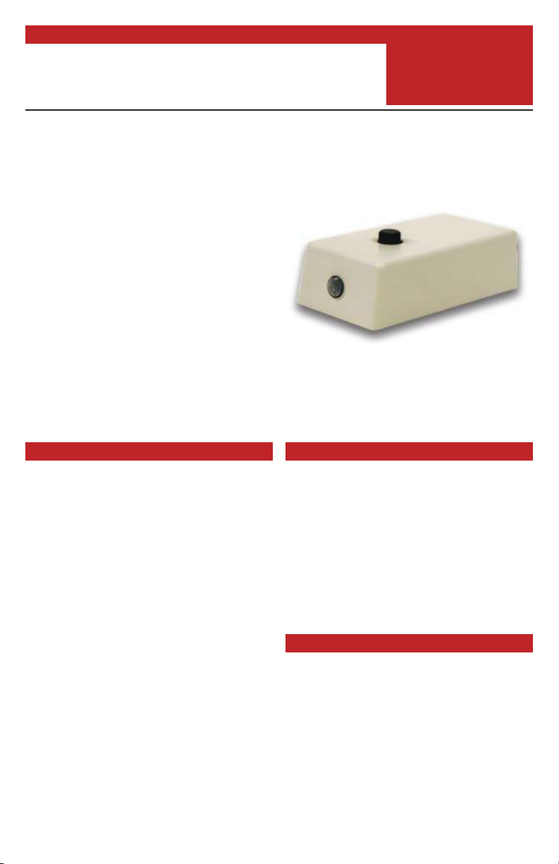
The PB-1 Panic Button Kit connects to
a Viking 1600A or 1600-IP Series
Emergency Phone to provide a one-way
talk path to the pre-programmed
number when used.
The PB-1 will activate the 1600A or
1600-IP Series Emergency Phone and
allows the called party to light a red LED
to indicate that the call is connected.
The called party will be able to hear the
installation site, but the site will not be
able to hear the called party. This makes
it a very effective security measure, as
there is no other indication that the site
is being monitored.
Features
• LED to indicate call connected
• One-way talk path for listening
without audible indication
• Unobtrusive - mount anywhere at any
angle with supplied foam tape
• Provides security and peace of mind
• Switch can be used to trigger inputs
on K-2000-DVA, K-202-DVA, SLP-1,
SLP-4, etc.
www.vikingelectronics.com
Information: (715) 386-8861
Applications
• Courtrooms
• Bank tellers
• Gas stations
• Motel reception desks
• All night restaurants
• Convenience stores
Specifications
Dimensions: 65mm x 35mm x 20mm
(2.56” x 1.38” x 0.79”)
Shipping Weight: 0.05kg (0.1 lbs)
Environmental: 0°C to 32°C (32°F to
90°F) with 5% to 95% noncondensing
humidity
Cord Length: 7 ft
Connections: (1) RJ11 jack, (1) 10-
position JST connector, (6) gel-filled butt
connectors
Installation
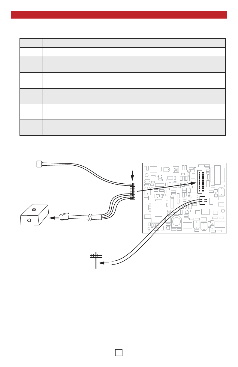
A. Connecting to a Viking 1600A Series Analog Emergency Phone
Step 1. Mount the PB-1 using the supplied foam tape.
Step 2. Connect the RJ11 plug on the supplied cable to the PB-1.
Step 3.
Step 4.
Step 5.
Step 6.
Step 7.
Disconnect the installed white connector from the 1600A Series
Emergency Phone board.
Remove the 1600A Series Emergency Phone board and then remove the
installed mic by carefully pulling it out of the black plastic mic mount.
Place the mic from the PB-1 cable into the mic mount and replace the
1600A Series Emergency Phone board.
Connect the white connector on the PB-1 cable to the 1600A Series
phone board.
Connect the phone line to the red and green wires from the 1600A Series
Emergency Phone board.
Mic
PB-1
to PB-1
Connect to
phone line
White
Connector
Red
Green
1600A Series Circuit Board
2

B. Connecting to a Viking 1600A-EWP Series Analog Emergency Phone
Step 1. Mount the PB-1 using the supplied foam tape.
Step 2. Connect the RJ11 plug on the supplied cable to the PB-1.
Step 3.
Step 4.
Step 5.
Step 6. Attach the red wire from the board to the yellow wire from the PB-1.
Step 7.
Step 8.
Step 9. Cut the two white wires leading to the speaker from the 1600A board.
Step 10. Connect the phone line to the red and green wires from the PCB.
Cut the PB-1 cable at the white connector, discard the connector and
mic.
Cut the black and red wires leading to the LED from the 1600A Series
board, leaving at least 1 inch of wire at the connector.
Attach the black wire from the board to the black wire from the PB-1
using a gel-filled butt connector (do not strip prior to inserting).
Cut the two black wires leading to the switch from the 1600A Series
board, leaving at least 1 inch of wire at the connector.
Attach one black wire to the red wire, and one to the green wire from the
PB-1 (non-polarity sensitive).
Speaker
Cut
PB-1
C.O. Line
to PB-1
OR
Analog
PABX/KSU
Station
Yellow
Black
Switch Wires
Green
Red
+ Yellow
- Black
LED Wires
Green
Red
3
Black
Black
+ Red
- Black
White
White
1600A-EWP
Series
Circuit Board
 Loading...