

Page 1
Designed, Manufactured and Supported in the USA
PA-IP
SIP / Multicast Paging
VIKING
PRODUCT MANUAL
SECURITY & COMMUNICATION SOLUTIONS
PoE Powered VoIP Endpoint Interfaces Analog Paging
Systems with SIP and Multicast Paging Sources
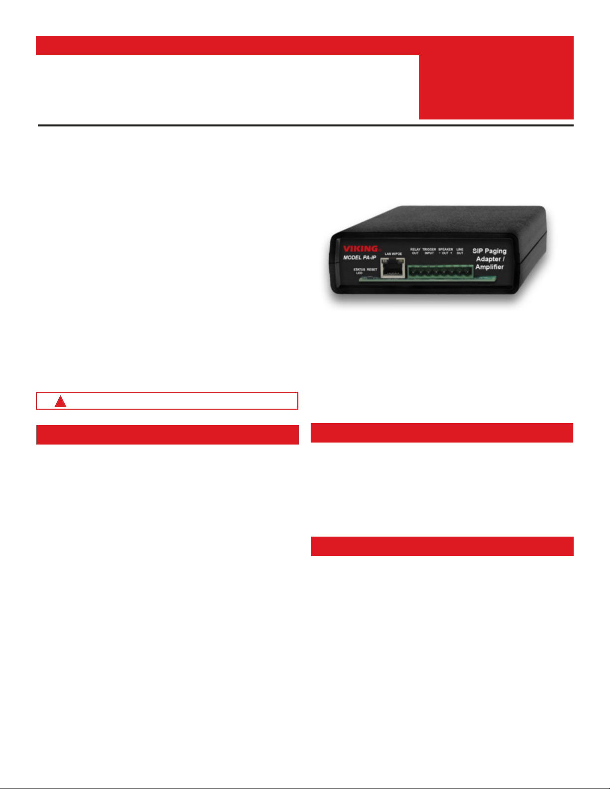
The Viking model PA-IP SIP / Multicast Paging Adapter
provides an interface between new VoIP phone systems
(hardware or hosted/cloud based) and analog paging systems,
eliminating the need for an ATA or FXS port. The PA-IP can
be used for standard SIP endpoint paging or multicast paging
and multicast background music.
The unit easily connects with a single CAT5/6 cable from your
PoE switch. The night ring feature is programmable for time
of day and day of week to enable loud ringing for after hour
incoming calls. Alternatively the night ring feature can be
enabled by a contact closure across the trigger input terminals.
Line-level audio output connections are provided for
connecting to an external amplifier.
A built-in 6 Watt class D amplifier with speaker output
connections are also provided to drive up to six analog
speakers. A programmable relay output is provided for
triggering external amplifiers, etc.
Adapter with Amplifier
July 16, 2019
Installation requires a Network Administrator / IT Technician
!
Features
• SIP compliant (See page two for list of compatible SIP servers and IP
phone systems)
• PoE powered (class 3, <13 Watts)
• Paging prioritization
• Plays audio from multicast
• SIP endpoint or multicast group member
• Supports up to ten multicast paging groups
• Red “Page/Status” LED indicator
• Network downloadable firmware
• Built-in high efficiency 6 Watt class D amplifier
• Can drive up to 6 external analog speakers
• Relay for activating door locks, strobe lights, external amplifiers, etc.
• SIP/Multicast: SIP page, SIP page and zoned multicast receive
• Support for access code to prevent unwanted SIP calls
• Line-level audio output for connecting to an external amplifier
• Network remote volume control
• Diagnostics (for testing the relay)
• Programmable pre page alert tone
www.VikingElectronics.com
Applications
• Amplified SIP endpoint or multicast IP paging for: schools, hospitals,
retail stores, office spaces, etc.
• Provide multicast background music and sound masking
• IP phone system integration with traditional analog amplifier (e.g.
single zone voice paging)
Specifications
Power: PoE class 3 (<13 Watts)
Dimensions: 5” x 5.25” x 1.5” (127mm x 133mm x 38mm)
Shipping Weight: 1.0 lbs (0.45 kg)
Operating Temperature: -40°F to 140°F (-40° C to 60° C)
Humidity: 5% to 95% non-condensing
Audio Codecs: G711u, G722* and G711a*
Network Compliance: IEEE 802.3 af PoE, SIP 2.0 RFC3261, 100BASE-TX with
auto cross over
Regulatory Compliance: CE, FCC Part 15 and Canada ICES-003 Class A
Frequency Response: 55 – 18,000 Hz (+/- 10 dB)
Connections: (1) RJ45 10/100 Base-T, (1) 8 position terminal block
Amplifier: 6 Watt Class D (capable of driving up to six 8 Ohm speakers connected
in parallel)
Maximum Output Level driving one Viking Model 40AE Ceiling Speaker: 105
dB SPL @ 1M
*NOTE: The PA-IP does not support multicast paging using the G722 or G711a Codec.
Page 2

Viking VoIP SIP System Compatibility List
Note: Exclusion from this list means only that compatibility has not been verified, it does not mean incompatibility.
On-Premise
3COM VCX
3CX
Allworx*
Aastra
Asterisk
Atcom
Avaya Aura Platform
Avaya IP Office Platform
BlueBox
Brekeke
Cisco Unified Communications Manager (CUCM)*
Cisco Unified Communications Manager Express
(CUCME)
Elastix
epygi QX200*
Freeswitch
Grandstream*
Interactive Intelligence
iPECS (Ericsson-LG)*
Iwatsu ECS*
Kamailio
Mitel 3300
NEC
OfficeSIP
OpenSIPS
Panasonic** (with SIP Extension Card)
PolyCom (SIP paging only)
Samsung Communications Manager (SCM)
ShoreTel*
Siemens Communications Server (SCS)
SIP Express Router (SER)
Snom PBX
Sonus
Switchvox
Teksip
Toshiba
Vertical Wave*
Yealink T Series S IP Phones
Cloud Based Service Provider
Callcentric*
iptel.org
MetaSwitch
Ring Central
sip.antisip.com
Switchvox
unify
Vertical Wave*
Voice Carrier
VoIP.MS*
* Note: For vendor specific detailed configuration instructions, see Configuring Viking VoIP Phone and SIP
Servers, DOD 944.
** Note: Relay operation commands are Not compatible with Panasonic Phone Systems (Panasonic does not
transmit DTMF between station ports).
2
Page 3

Definitions
Client: A computer or device that makes use of a server. As an example, the client might request a particular file from the server.
DHCP: Dynamic Host Configuration Protocol. In this procedure the network server or router takes note of a client’s MAC address and
assigns an IP address to allow the client to communicate with other devices on the network.
DNS Server: A DNS (Domain Name System) server translates domain names (ie: www.vikingelectronics.com) into an IP address.
Ethernet: Ethernet is the most commonly used LAN
achieve transmission speeds up to 1Gbps.
Host: A computer or device connected to a network.
Host Name: A host name is a label assigned to a device connected to a computer network that is used to identify the device in various
forms of network communication.
Hosts File: A file stored in a computer that lists host names and their corresponding IP addresses with the purpose of mapping addresses
to hosts or vice versa.
Internet: A worldwide system of computer networks running on IP
IP: Internet Protocol is the set of communications conventions that govern the way computers communicate on networks and on the
Internet
IP Address: This is the address that uniquely identifies a host on a network.
LAN: Local Area Network. A LAN is a network connecting computers and other devices within an office or building.
Lease: The amount of time a DHCP
time, the lease can expire and the address can be assigned to another host.
MAC Address: MAC stands for Media Access Control. A MAC address, also called a hardware address or physical address, is a unique
address assigned to a device at the factory. It resides in the device’s memory and is used by network equipment to send data packets
to the correct IP address. You can find the MAC address of your PA-IP page adapter printed on a white label on the bottom side of the
chassis.
Router: A device that forwards data from one network to another. In order to send information to the right location, routers look at IP
Address, MAC Address and Subnet Mask.
RTP: Real-Time Transport Protocol is an Internet protocol standard that specifies a way for programs to manage the real-time transmission
of multimedia data over either unicast or multicast network services.
Server: A computer or device that fulfills requests from a client. This could involve the server sending a particular file requested by the
client.
Session Initiation Protocol (SIP): Is a signaling communications protocol, widely used for controlling multimedia communication sessions
such as voice and video calls over Internet Protocol (IP
which govern establishment, termination and other essential elements of a call.
Static IP Address: A static IP Address has been assigned manually and is permanent until it is manually removed. It is not subject to the
Lease
Subnet: A portion of a network that shares a common address component. On TCP/IP networks, subnets are defined as all devices
whose IP addresses have the same prefix. For example, all devices with IP addresses
same subnet. Dividing a network into subnets is useful for both security and performance reasons. IP networks are divided using a subnet
mask.
TCP/IP: Transmission Control Protocol/Internet Protocol is the suite of communications protocols used to connect hosts on the Internet.
TCP/IP uses several protocols, the two main ones being TCP and IP. TCP/IP is built into the UNIX operating system and is used by the
Internet, making it the de facto standard for transmitting data over networks.
TISP: Telephone Internet Service Provider
WAN: Wide Area Network. A WAN is a network comprising a large geographical area like a state or country. The largest WAN is the
Internet
Wireless Access Point (AP): A device that allows wireless devices to connect to a wired network using Wi-Fi, or related standards. The
AP usually connects to a router (via a wired network) as a standalone device, but it can also be an integral component of the router itself.
Wireless Repeater (Wireless Range Extender): takes an existing signal from a wireless router or access point and rebroadcasts it to
create a second network. When two or more hosts have to be connected with one another over the IEEE 802.11 protocol and the distance
is too long for a direct connection to be established, a wireless repeater is used to bridge the gap.
.
server reserves an address it has assigned. If the address isn’t used by the host for a period of
limitations of a Dynamic IP Address assigned by the DHCP Server. The default static IP Address is: 192.168.154.1
.
technology. An Ethernet Local Area Network typically uses twisted pair wires to
protocol which can be accessed by individual computers or networks.
) networks. The protocol defines the messages that are sent between endpoints,
that start with 100.100.100. would be part of the
3
Page 4
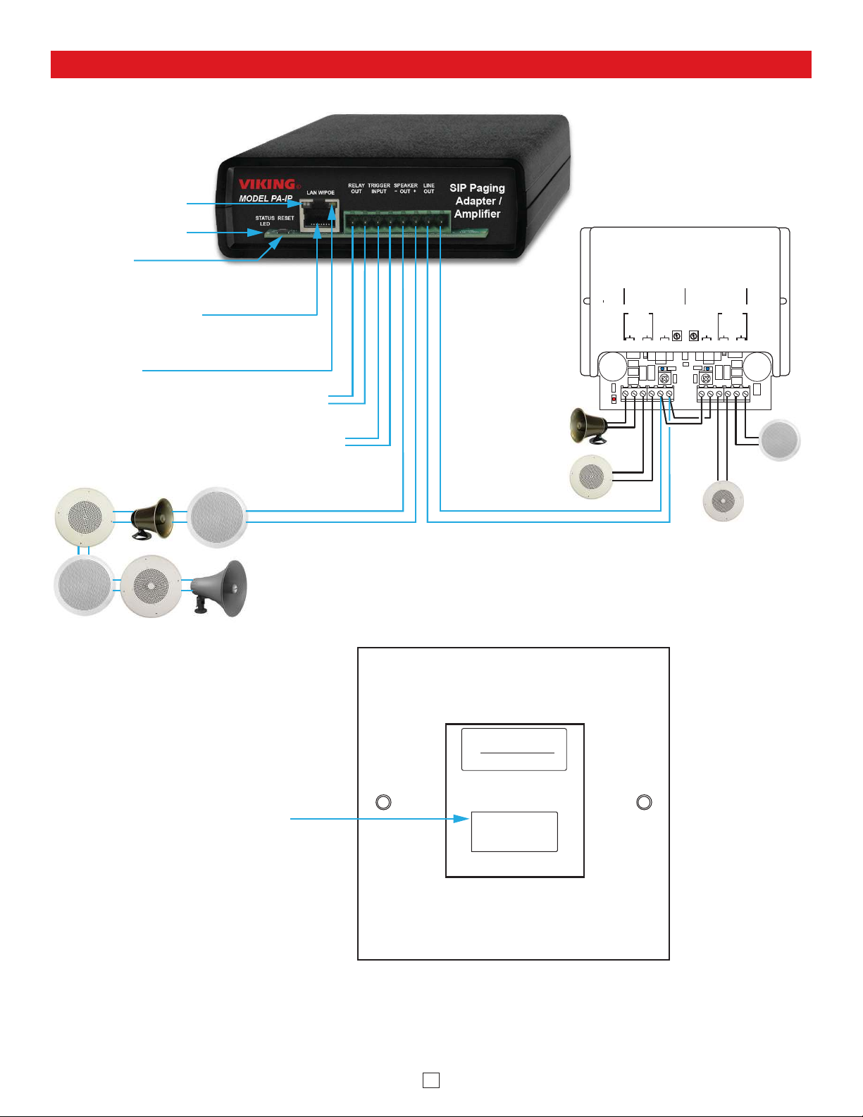
Features Overview
Switch or Contact Input: To Enable Night Ring Feature
Relay Output Contact (2A@30VDC / 250VAC max):
Connect to trigger input of amplifier, etc.
MAC Address Label:
The MAC address is a unique 12 digit
number used by network equipment to send
data packets to the correct IP address.
PoE LAN Port 10/100, PoE Class 3 (<13 Watts):
Connect to your LAN via RJ45 plug and CAT5
or greater twisted pair wire.
Yellow Network Status LED: Lights steady to
indicate power and data link. Blinks to indicate
network activity.
Green Unit Status LED
VIKING©
VIKING
ELECTRONICS
HUDSON,
WI
54016
60 WATT 2 ZONE
POWER AMPLIFIER
PWR 60 W
+/ 24 VDC
MODEL PA-60
SPKRS
PWR
LED
SPKRS
LINE LEVEL AUDIO INPUT
GAIN GAIN
70V OUT
SPKRS
SPKRS
LINE LEVEL
AUDIO INPUT
70V OUT
CHANNEL 2 CHANNEL 1
2315 7101112
46
8
9
Up to (15)
8 Ohm Speakers
(30AE shown,
not included)
Up to (15)
8 Ohm Speakers
(35AE shown,
not included)
Up to (15)
8 Ohm Speakers
(40AE shown,
not included)
Line Out
600 Ohm
Paging
Audio
Optional Paging Amplifier
Viking model PA-60 shown (DOD 493)
Bottom View
VIKING
Model:
xxxxxx
Viking Electronics, Inc. (715) 386-8861
1531 Industrial St., Hudson, WI 54016
www.vikingelectronics.com DOD#
S/N: XXXXXXXX
P/N: DEV:
xxxxxxxx
MAC: 18E80FXXXXXX
Speaker Out
30AE
25AE
35AE
Up tp (6) Optional Viking Analog
Speakers, see DOD 497 and 498
(not Included)
+
_
300AE
40AE
Up to (15)
8 Ohm Speakers
(25AE shown,
not included)
40AE
Red Page / Status LED
Reset Button
4
Page 5
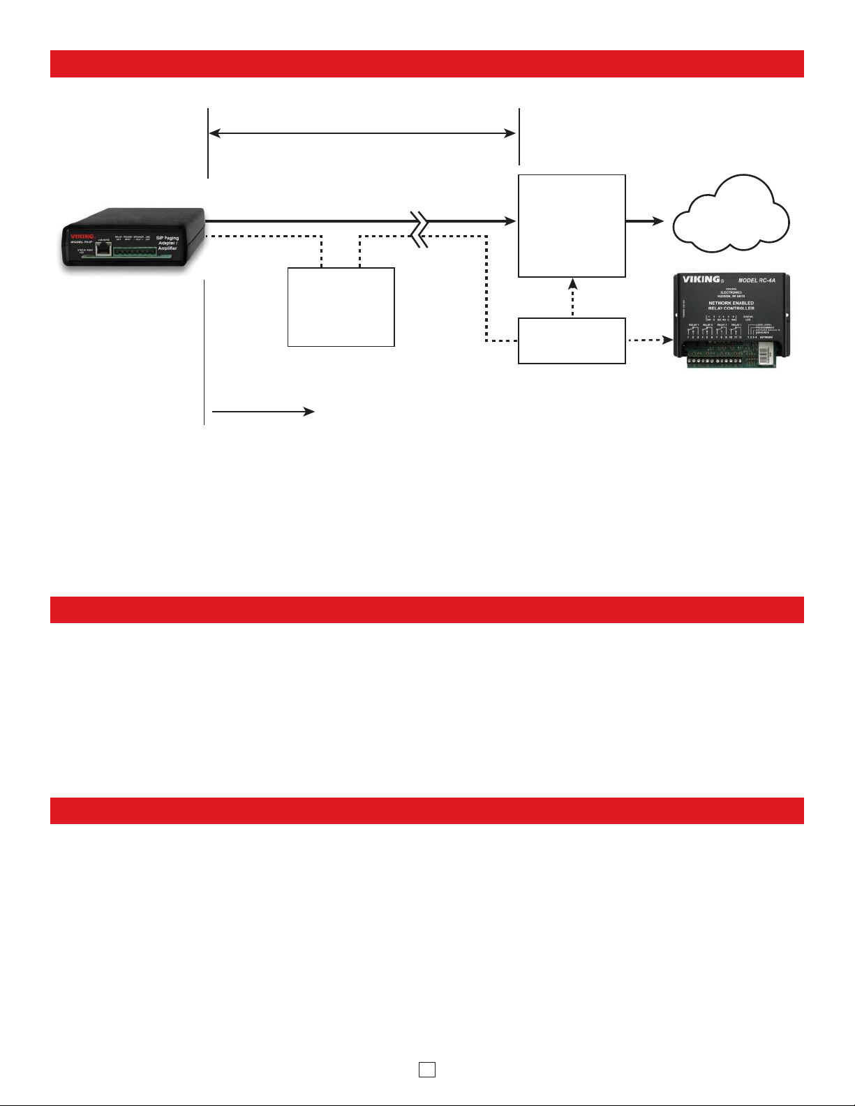
Typical Installation on SIP Based VoIP Phone System
100m (328 ft) maximum*
Viking
PA-IP
10/100 Mbps
Maximum
SIP VoIP PBX
or
PC with
SIP Server
Software
Optional
PoE Injector
(If VoIP PBX does
not have PoE)
**Optional
Switch / Hub
Viking
supplies
* Note: A PoE extender can be used for an additional 100 meters per extender. For longer
runs (up to 2 km / 1.2 miles) a ethernet to fiber media converter can be used.
** Network Port Settings
• Make sure the port is not in trunk mode
• Make sure port is capable of 100mbps full duplex
• Disable Spanning Tree Protocol (STP) or enable Portfast
Customer’s
Responsibility
(Extends range of cable, keeps
1 Gbps network speed for other
equipment on network)
Internet
Optional Viking model RC-4A
Secure Remote Relay
Controller, see Programming
section 12 (DOD 582)
PC Requirements
• IBM compatible personal computer with:
Windows 7, 8 or 10
• Adobe Acrobat Reader 8 or higher
• PA-IP hardware
• Available LAN with PoE (class 3, <13 Watts)
• Ethernet cable (CAT5 minimum)
• 1 MB
minimum free hard drive space for installation
• 16MB of free physical RAM
PC Programming
Download and install the programming software
1. Go to www.vikingelectronics.com and enter PA-IP in the search box
2. Click PA-IP in the search results
3. Scroll down the page to Downloads, click IP Programming Software
4. Install the programming software by saving or opening the file and then clicking on setup Viking IP
Programming.exe
5. Follow the prompts on your screen to complete software installation
6. To start the Viking IP Programming application, click on the Viking IP Programming icon on your desk
top. The Main screen will appear, allowing the user to program any PA-IP connected to that LAN.
Note: PC must be connected to the same LAN as the PA-IP.
5
Page 6
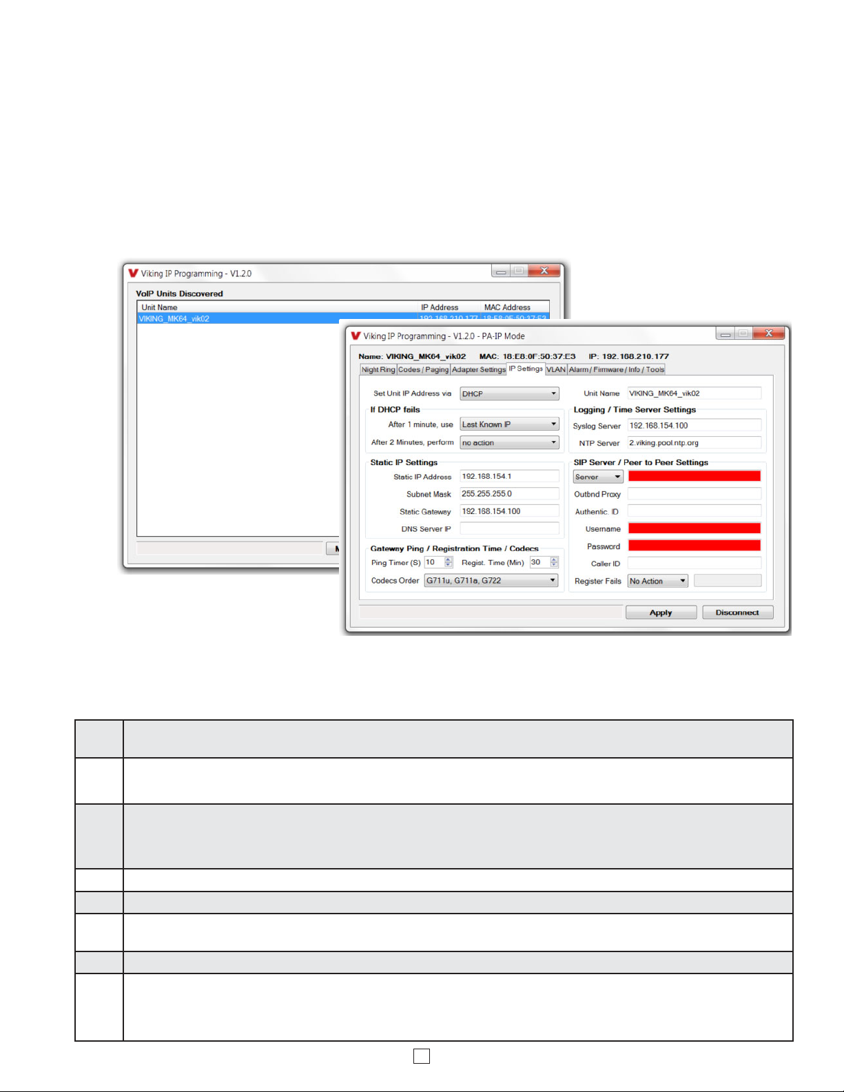
A. Connect/Disconnect
Open the “Viking IP Programming” software on the PC and the start screen shown below will appear. Any Viking IP
products that are connected to the network will appear on the list. Simply select the PA-IP on the list and click on the
“Connect” button at the bottom or double click the selected unit. If no username and password have been programmed
and the security code of the selected unit is still set to default (845464), the PC software will not require entering a
username, password or security code to connect to the PA-IP. If the PA-IP has been programmed with a username
and password, a pop up window will ask for the username followed by the password. If the unit’s security code has
been changed from “845464”, it will then prompt for the correct security code. PA-IP’s have a default name of
“uCMK64_40TB-IP”, so if many PA-IP’s are connected to the same network and all have the default name, MAC
addresses must be used to identify each PA-IP. When finished programming, click on the “Disconnect” button at the
bottom. Closing the program will also automatically disconnect the unit.
B. Configuring the PA-IP Network Settings
Step 1.
Step 2.
Step 3.
Step 4. The program will then read and display the PA-IP’s IP and programming settings.
Step 5. Click on the “IP Settings” tab.
Step 6.
Step 7. Set the “Unit Name”, “Logging / Time Server Settings” as needed.
Step 8.
Open the “Viking IP Programming” software on a windows PC that is connected to the same LAN as the PA-IP speaker to be
programmed.
The window in the upper left corner of the menu will show you each PA-IP that is connected to that LAN. Select the unit with the same
MAC address shown on the label located on the top of the Ethernet connector on the PA-IP or the matching label that can be found on
the bottom of the Black Box.
Click on the “connect” button. A default PA-IP has no username or password programmed, the security code is set to “845464” and
when configured this way, you are instantly connected to the PA-IP. If the PA-IP has been programmed with a username and
password, a pop up window will ask for the username followed by the password. If the unit’s security code has been changed from
“845464”, it will then prompt for the correct security code, then click “retry”.
Select the appropriate value Static IP Settings or DHCP for “Set Unit IP Address via”. Note: Changing the IP address will cause you to
have to reconnect to the unit. Enter the values for the fields in “if DHCP fails” or “Static IP Settings” as needed.
Select Peer-Peer in the “SIP Server / Peer to Peer Settings” to use the unit in Peer to Peer mode or for Multicast paging only. Select
Server to register with a SIP registrar server and fill in the “Outbnd Proxy” (SIP Outbound Proxy Server Address, “ip:port”), “Authentic. ID”
(SIP Authentication ID), “Username” (SIP Username, <string>), “Password” (SIP Password), and “Caller ID” (SIP Caller ID) with values
from your VoIP provider. Required fields will be red when the unit is not registered.
6
Page 7

C. Configuring PA-IP VLAN Settings
Step 1. Click on the “VLAN” tab
Step 2. Disable or enable VLAN tagging by setting the value of “VLAN Tagging”.
Step 3. Set the VLAN tag ID by selecting an integer (1 to 4094) in “ID for all packets”.
Step 4.
Set the Priority Code Point (PCP) value for all not SIP and RTP packets in the “PCP for all packets” input (0 is default, priorities are
from low to high: 0, 1, 2, 3, 4, 5, 6, 7). Set the “PCP for SIP packets” (3 is default). Set the “PCP for RTP packets” (5 is default).
D. Manually Resetting the Security Code to Enter Programming
Note: This procedure will not erase a username and password used to access the PA-IP program mode. Only the security code is set to default.
Step 1. Power down the PA-IP by disconnecting the LAN Cable (RJ45 plug).
Step 2. Press and hold the Reset button, then reconnect the LAN Cable (RJ45 plug).
Step 3.
Step 4. The security code is now reset to 845464 (factory default).
Step 5. You can now enter programming by following the steps in section A.
Continue to hold the Reset button until you hear 2 beeps, (approximately 6 seconds). Then release the button. The Status LED will
remain off for the first 3 seconds, flash slowly for 3 seconds then fast flash (after 2 beeps), indicating when to release button.
E. Manually Resetting All Network Parameters to Factory Default
Note: This procedure will erase a username and password that are used to access the PA-IP program mode.
Step 1. Power down the PA-IP by disconnecting the LAN Cable (RJ45 plug).
Step 2. Press and hold the Reset button, then reconnect the LAN Cable (RJ45 plug).
Step 3.
Step 4. You can now enter programming by following the steps in section A.
Continue to hold t he Reset button until you hear 2 beeps, (approximately 6 seconds). Continue to hold Reset button until you hear 4
more beeps, (approximately 6 seconds later), then release the button. The Status LED will remain off for the first 3 seconds, flash
slowly for 3 seconds (2 beeps), fast flash for 6 seconds (4 beeps), then light steady indicating when to release button.
7
Page 8

Programming Features Index
DESCRIPTION Section Page
Connect/Disconnect A 6
VLAN Settings C 7
Unit Name 1 9
SIP Server 2 9
Peer to Peer Settings 3 9
Outbound Proxy 4 9
Authentication ID 5 9
Register Fails (Re-Resolve or Alternate Server) 6 9
Security code (factory set to 845464) 7 10
Access Code (1 - 6 digits, blank = disabled, factory set to 123456) 8 10
SIP Page Priority over Multicast Page 9 10
Multicast Paging 10 11
Multicast Paging Volume (0 - 19, factory set to 1) 11 11
Internal / External Relay (factory set to internal) 12 11
Relay Mode (Door Strike, Paging, Alarm, Ring, Ring Flash, factory set to Door Strike) NOTE: Normally closed
modes can also be programmed.
Relay Activation Command (1 or 2 digits, factory set to QQ) NOTE: Relay Mode must be set to Door Strike
Relay Activation Time (0.5 - 99 seconds, factory set to 5 seconds) 15 12
Relay Buzz Volume (1 - 3 or Disabled, factory set to 3) 16 12
Relay Latch Commands (Enabled or Disabled, factory set to Enabled) NOTE: Relay Mode must be set to Door
Strike
SIP Paging Volume (0 - 19, factory set to 1) 18 12
Ring Volume (0 - 19, factory set to 5) 19 12
SIP Page Length Time Out (disabled or 1 - 9 minutes, factory set to 3 minutes) 20 12
Multicast Page Length Time Out ( 1 to 255 seconds or Disabled, factory set to 180 seconds) 21 13
Inbound Call Mode (Disabled, Auto Answer, Auto Answer-Secure or Ring, factory set to Auto Answer) 22 13
Ring Cadence (factory set to Normal, 2 seconds on 4 seconds off) 23 13
LED Mode (OFF, ON or Paging, factory set to Paging) 24 13
Line Out Control 25 13
DTMF Regeneration 26 13
Pre Page Tone 27 13
Mute Current / Next Alarm 28 14
Permanent Alarm Mute 29 14
Programming User name and Password 30 14
IP Firmware 31 14
Unit Firmware 32 14
Import/Export 33 15
Clear Adapter Settings 34 15
Clear IP Settings 35 15
Diagnostics 36 15
Night Ring Timed Operation 37 15
Time Zone Settings/daylight Saving Time 38 15
13 12
14 12
17 12
8
Page 9

Programming Features
1. Unit Name
Up to a 31 character unit name can be assigned to the PA-IP being programmed.
2. SIP Server
Enter the IP address or URL of your SIP server or service provider in this field. The SIP server IP address is limited to
74 characters. Note: If an alternate SIP server IP address is programmed, the IP address for the SIP server and
alternate SIP server will be limited to 31 characters. Note: If outbound proxy is not required, enter the SIP server IP
address into the Outbnd Proxy field.
3. Peer to Peer Settings
When set to Peer to Peer mode a SIP server is not used. The unit should be programmed with a Static IP Address and
Username, a password is not used. Caller ID can be programmed if needed. Simply call the unit by entering the
programmed “username@192.168...(Static IP address for the unit)”. The static IP address is normally programmed into
a page button on the VoIP telephones. Note: Peer to Peer mode does not affect Multicast paging.
4. Outbound Proxy
If your SIP provider requires an outbound proxy IP address enter it in the “Outbnd Proxy” field. Note: If Outbound
Proxy is not required, leave this field blank.
5. Authentication ID
If your SIP provider requires Authentication ID, enter it in the Authentic. ID field. If Authentication ID is not required,
leave this field blank.
6. Register Fails (Re-Resolve or Alternate Server)
When registered to a SIP server in the event that registration is lost you can program the unit to re-resolve using the
current SIP server IP address or route pages through an alternate SIP server. With Alternate Server selected enter the
IP address of the alternate SIP server in the field next to the Register Fails drop down box. Note: With an alternate
SIP server IP address programmed, the IP address for the SIP server and alternate SIP server will be limited to 31
characters.
9
Page 10

7. Security Code
The security code allows the user/installer to program the PA-IP with a PC and the required ‘Viking IP Programming”
software. If the security code is left as default, the PC software won’t require entering a security code when connecting
to the PA-IP. It is recommended that the factory set security code be changed. The security code can be set back to
default by holding the Reset button while the PA-IP powers up. See section D on page 7 for details. It can also be
defaulted by connecting to the unit with the IP Programming Software and clicking on the “Clear Adapter Settings” button
on the “Alarm / Firmware” tab. Factory Setting: 845464
Note: The security code must be 6 digits and cannot include a Q or #.
8. Access Code
The Access Code is primarily used along with the “Auto Answer Secure” Inbound Call Mode to force inbound SIP page
callers to dial the Access Code before they can make a SIP page. The Access Code also comes into play when using
the relay of the PA-IP to open a door or gate. When you call the PA-IP and the unit automatically answers the call (see
Programming section 22), you must dial the Access Code before you are allowed to operate the door strike relays, as
extra security on inbound calls. Once a tenant has entered the correct Access Code, 2 beeps are heard and the user
can now enter any “Operation Commands” (see Operation section C). The Access Code can be disabled if this basic
security is not required. Factory Setting: 123456
Note: The Access Code can be 1 - 6 digits in length and cannot include a Q or # or match the numbers used for the
Security Code.
9. SIP Page Priority over Multicast Page
Incoming PA-IP SIP call audio streams can be programmed to have priority over any of the 10 Multicast paging groups.
Simply Use the “Sip Page Priority Level” drop down menu to select which Multicast group you want SIP calls to have
priority over. Factory Setting: 0 (highest priority)
10
Page 11

10. Multicast Paging
The PA-IP is designed and tested to be compatible with FreeSwitch Multicast Paging. Up to 10 multicast paging groups
can be programmed into each PA-IP page adapter. Each multicast group is defined by a multicast address and port
number. Each multicast group is assigned a priority, allowing simultaneously arriving pages to be serviced based on
importance. A timeout check box can be selected for each paging group. See Multicast Page Length Time Out under
Speaker Settings to adjust the timeout from 1 to 255 seconds. Only one timeout time can be programmed for all
Multicast groups. By default groups 0-8 have the timeout enabled, group 9’s timeout is disabled. This is useful for
background music.
Assigning Priority
The PA-IP will prioritize simultaneous Multicast audio streams according to their priority in the Paging Sources list.
Group 0 will have the highest priority while group 9 will have the lowest priority. Group 9 is useful for a low priority
stream such as background music. Group 0 is useful for high priority streams such as emergency messages.
The multicast paging groups can also be used for up to ten different paging zones for receiving audio streams. A paging
zone can consist of one or many PA-IP multicast page adapters. There is no limit to how many page adapters can be
in a given paging zone. Each multicast group is defined by a multicast address and port number. Each multicast group
is assigned a priority, allowing simultaneously arriving pages to be serviced based on importance.
11. Multicast Paging Volume
The volume of each individual multicast page can be adjusted from 0 - 19. Factory Setting: 1
12. Relay Internal / External
With the relay set to “Internal” the PA-IP will activate its on board relay for amplifier signaling, door strike, gate control,
etc. The Relay must be set to “External” when using a Viking remote model RC-4A relay controller to activate external
relays instead. Factory Setting: Internal
11
Page 12

13. Relay Mode
Door Strike Mode (Factory Setting): When programmed for Door Strike Mode the relay is intended for door strike,
maglock or gate control. Select NC Door Strike Mode to provide normally closed contacts.
Paging Mode: When programmed for Paging the relay will activate whenever a page is active. This mode is useful
for triggering an external Amp. Select NC Paging Mode to provide normally closed contacts.
Alarm Mode: When programmed in Alarm Mode the relay will activate continuously while the unit is powered and
registered to the SIP server. In the event the unit loses power and/or SIP registration the relay will turn off, which can
be used to signal an alarm device. Note: Alarm mode cannot be used with external relay control (RC-4A). Select NC
Alarm Mode to provide normally closed contacts.
Ring Mode: When programmed for Ring Mode the relay will continuously activate while the PA-IP’s extension is called
and the PA-IP is set to loud ring (see Programming sections 22 and 37). This mode is useful for activating a Viking
model SL-2 strobe light, etc. Select NC Ring Mode to provide normally closed contacts.
Ring Flash Mode: When programmed for Ring Flash Mode the relay will momentarily turn on and off in a 400ms
on/off cadence while the PA-IP’s extension is called and the PA-IP is set to loud ring (see Programming sections 22
and 37). This mode is useful for activating a Viking LPL-1 Remote Visual Indicator, etc. Select NC Ring Flash Mode to
provide normally closed contacts.
14. Relay Activation Command (Relay Mode must be set to “Door Strike”)
The one or two digit code stored in the Relay Activation Command is the touch tone command that the person calling
the PA-IP must enter on their phone in order to momentarily activate the relay. The code can contain the characters 0
- 9, # or Q. The code cannot match a relay latching command. The code must be entered while the remote phone is
communicating with the PA-IP. If an access code is set it will need to be entered first. This can be disabled by leaving
the access code blank. Factory Setting: QQ
15. Relay Activation Time (Relay Mode must be set to “Door Strike”)
The value stored in the Relay Activation Time is the amount of time the relay will be energized after a correct momentary
touch tone command is entered. This number can range from 0.5 to 99 seconds. Factory Setting: 5 seconds
16. Relay Buzz Volume (Relay Mode must be set to “Door Strike”)
The relay activation tone is a buzzing sound that is heard over the audio outputs when the door strike relay is activated.
After the calling party enters the correct relay activation command, the calling party and audio outputs will hear 2 short
confirmation beeps followed by a buzzing sound (relay activation tone) while the door strike relay is activated. The tone
(buzz) length will match the relay activation time up to a maximum of 5 seconds. The tone (buzz) can be programmed
to three different volume settings 1 = Low, 2 = Medium, 3 = High or it can be disabled. When set to “Disabled” the
confirmation beeps will not be heard. Factory Setting: 3
17. Relay Latch Commands (Relay Mode must be set to “Door Strike”)
When set to “Enabled” the Operation Commands (Q0 to Q1) to Un-Latch or Latch the relay are enabled.
When set to “Disabled” the Operation Commands (Q0 to Q1) to Un-Latch or Latch the relay are disabled. Disabling the
Latch commands can be useful in applications where you want to eliminate the possibility of inadvertently entering a
latch command leaving a gate open/closed, etc. Note: The momentary relay cammand is still allowed.
Factory Setting: Enabled
18. SIP Paging Volume
The SIP Paging volume can be set from 0 - 19. 0 = lowest volume setting, 19= highest volume setting. Adjusting this
will set the volume level for SIP Paging. Factory Setting: 1
19. Ring Volume
When the Inbound Call Mode (see Programming section 22) is set to Ring, the PA-IP will output a loud ring when it is
called. The volume level of the loud ring can be adjusted from 0 - 19. Factory Setting: 5
20. SIP Page Length Timeout
This feature selects the maximum length of time that incoming SIP calls can be connected. Programmable in increments
of 1 minute up to a maximum of 9 minutes or disabled. With the call length disabled, the PA-IP must rely on a call
ended signal or Touch tone # to hang-up. Factory Setting: 3 minutes
12
Page 13

21. Multicast Page Length Timeout
The Multicast Page Length Timeout can be programmed from 1 to 255 seconds in one second increments.The Time
Out can also be disabled, allowing any length of Multicast page or continuous background music. The multicast timeout
can be individually enabled or disabled for each multicast page group using a checkbox provided for each paging
source (on the “Codes / Paging” tab). The same timeout time applies to all multicast page groups that have the multicast
timeout enabled. Factory Setting: 180 seconds.
22. Inbound Call Mode
The Inbound Call Mode determines how the PA-IP handles incoming SIP calls. One option is to generate a loud ring
sound. The PA-IP can also auto answer the call, to allow SIP paging or remote control of the relay. The “secure” option
for auto answer require the callers to dial the access code in order to transmit a page. Factory Setting: Auto Answer
Disabled – Inbound SIP calls are not allowed.
Auto Answer – Inbound SIP calls are auto answered on the first ring and can page over the audio outputs.
Auto Answer Secure – Inbound SIP calls are auto answered and the caller must dial the access code in order to
make a page.
Ring: In the “Ring” mode the unit will not automatically answer an incoming SIP call but will output a loud ring signal
in a factory programmed 2 seconds on, 4 seconds off ring pattern (pattern / cadence is selectable).
23. Ring Cadence
When the PA-IP is set to loud ring on incoming SIP calls, you can select the ring cadence of the loud ring sound. It
can be programmed to one of four different cadences. Factory Setting: Normal Ring
Normal Ring (single ring: 2 seconds ON, 4 seconds OFF) factory setting
Double Ring (double ring: 1 second ON, 0.5 second OFF, 1 second ON, 3.5 seconds OFF)
Short-Short-Long (triple ring: 0.5 second ON, 0.5 second OFF, 0.5 second ON, 0.5 second OFF, 1 second ON, 3 seconds OFF)
Short-Long-Short (triple ring: 0.5 second ON, 0.5 second OFF, 1 second ON, 0.5 second OFF, 0.5 second ON, 3 seconds OFF)
24. LED Mode
The “Page / Status” LED on the PA-IP can be programmed to one of three different modes.
Factory Setting: Paging Mode
OFF Mode: In this mode the LED will not light during normal operation. It will only light (blink) if it cannot register with
the programmed SIP server or while manually resetting all network parameters to factory default.
On Mode: The LED will remain ON when the unit is powered and registered. The LED will flash if registration is lost
and alarm is active.
Paging Mode: The LED will remain OFF in the idle state, light steady when the page is active, then turn OFF when
the call is completed. The LED will also light steady during Multicast paging.
25. Line Out Control
When Line Out Control is set to enabled, SIP page audio will be heard from the Line Level Output. When this feature
is disabled, the Line Level Output is muted during SIP page calls. The Line Level Output still receives multicast audio
and the speaker output still receives SIP page audio when the Line Out control is disabled. Factory Setting: Enabled
26. DTMF Regeneration
When DTMF Regeneration is Enabled, any touch tones entered by the caller (in band or out of band) will be passed
along to the line out and speaker out. These tones are used by a zone controller or external amplifier to choose which
zone to send the page audio to. Factory Setting: Disabled
27. Pre Page Tone
When enabled, a short beep will be heard prior to SIP or Multicast paging audio. The volume of the Pre Page Alert
Tone will match the volume setting of the SIP or Multicast page. Factory Setting: Enabled
13
Page 14

28. Mute Current / Next Alarm
A network failure alarm will be indicated by providing 3 beeps over both audio outputs every 30 seconds but only when
Permanent Alarm Mute is set to Alarm Tones Enabled (Permanent Alarm Mute is set to Alarm Tones Disabled by default). A
network failure indicates the unit is not registered to the SIP server or there is a communication failure with the gateway. The
three beeps can be muted by clicking on “Mute Current / Next Alarm” button in the IP Programming software or pressing and
holding the Reset button for five seconds. The Status LED will continue to flash to assist troubleshooting. The alarm beeps
can also be permanently disabled. See Permanent Alarm Mute below. Factory Setting: Disabled
29. Permanent Alarm Mute
Permanent Alarm Mute is set to Alarm Tones Disabled by default, so network failure alarms will not be indicated over the
audio outputs. Only the status LED will flash to indicate the network failure. To enable alarm tones over the audio outputs,
select Alarm Tones Enabled.
30. Programming a Username and Password to Restrict Access to Programming
To increase security, a username and password can be programmed to limit access to the PA-IP using Viking IP Programming
software. When no username and password are programmed and the security code is still set to default (845464), the PC
software will not require a username, password or security code when connecting to the PA-IP. If the PA-IP has been
programmed with a username and password, a pop up window will ask for the username followed by the password. If the unit’s
security code has been changed from default (845464), it will then prompt for the correct security code.
If the username and password are unknown, they can only be erased by resetting all network parameters to default with the
Reset button (see section E on page 7). If the username and password are known but you wish to erase them, that can be
accomplished by exporting the data from the PA-IP, resetting all network parameters to default with the Reset button (see
section E on page 7) or clicking on “Clear IP Settings” and then importing the data back into the PA-IP.
31. IP Firmware
Update IP is currently not available. The ability to update IP firmware will be made available in a later release of Viking IP
Programming software. If an IP firmware update is needed, Viking Technical Support will assist in updating the IP firmware.
32. Unit Firmware
If new Unit firmware is available, after opening the programming software a pop up window will ask if you would like to update
the firmware. Another way to update is accomplished by clicking the “Update Unit” button. You can then browse to the folder
that contains the HEX file for updating the unit’s firmware. This method is typically only used when Viking Technical Support
has sent you updated firmware.
14
Page 15

33. Import / Export
The Import/Export feature is useful for backing up all the PA-IP’s programming or for importing programming when
installing multiple units with a majority of the same programming.
34. Clear Adapter Settings
Clicking on the “Clear Speaker Settings” button in programming will reset all of the programming features back to their
factory default settings, including setting the unit’s security code back to the default value (845464).
Note: This command will not change or reset your IP settings or Multicast paging settings.
35. Clear IP Settings
Clicking on the “Clear IP Settings” will reset all of the IP settings back to their factory default settings. This also clears
Multicast IP address / port settings and erases any username and password programmed in the unit to restrict access
to programming.
36. Diagnostics
The Diagnostics section in the Viking IP Programming can be used to test the functionality of the relay. Note: This will
not work when relay mode is set to external or Alarm.
37. Night Ring Timed Operation
When Night Ring Timed Operation is enabled, if a SIP call is received during the programmed Start and Stop times,
the PA-IP will output loud ring on the “Line Out“ and “Speaker Out” terminals. This is selectable for each day of the
week. When outside of the Night Ring timing window, the Inbound Call Mode setting will determine how SIP calls are
handled. The Night Ring feature can also be enabled by providing a contact closure to the trigger input on the PA-IP.
All inbound SIP calls will cause the PA-IP to loud ring when the trigger input is shorted. Note: For timed Night Ringing
the unit must be synced with a time server. If the Night Ringing feature is enabled in the software you will be asked to
use Viking’s Time Server when changes are applied. The address will be entered by the software automatically.
38. Time Zone Settings
When using the Night Ring Timed Operation, the PA-IP must be synced with the network time. Set the Time Zone
Settings to match the settings on the network the unit is connected to for proper timed operation.
15
Page 16

Operation
A. Inbound SIP Calls
How inbound SIP calls are handled depends on the Inbound Call Mode selected (see Programming section 22), the
current programming for Night Ring Timed Operation if enabled (see Programming section 37), the current time of day
and day of week. If Night Ring Timed Operation is disabled and the Inbound Call Mode is set to Auto Answer, the
PA-IP will automatically answer inbound calls, provides a Pre Page Alert Tone if enabled and allows paging. When the
Inbound Call Mode is set to Auto Answer – Secure, the PA-IP auto answers inbound calls but the party must dial the
Access Code before they are allowed to page. The Inbound Call Mode also has a Ring option that allows the unit to
output a loud ring on any inbound SIP calls and the volume of the ring is adjustable (see Programming section 19).
The Night Ring feature can also be enabled by providing a contact closure across the trigger input screw terminals. If
Night Ring Timed Operation is enabled and an inbound SIP call is received between the programmed start and stop
times and the current day is a programmed active day, the unit will automatically output a loud ring instead of following
the Inbound Call Mode programming. This allows for loud ring at certain times of the day/days of the week and paging
all other times/days of the week.
B. Multicast
The PA-IP is compatible with FreeSwitch Multicast paging (see Programming section 10). Up to 10 multicast paging
groups can be programmed into each unit and each group is assigned a priority level allowing simultaneous arriving
multicast pages to be handled based on importance. Low priority groups are often used for low priority streams like
background music and high priority groups are used for high priority streams such as emergency messages. Additionally
a timeout limit can be set and either enabled or disabled for each multicast group. The volume of each group can be
programmed and SIP calls can be assigned either higher or lower priority than all or some of the multicast groups (see
Programming section 9).
C. Operation Commands (Relay Mode must be set to “Door Strike”)
The following commands can be entered after an inbound SIP call to the PA-IP, when the Inbound Call Mode is set to
auto answer. After the unit auto answers the call, one beep will be heard if Pre Page Alert Tone is enabled. If the
Access Code has been disabled, you can now enter the Operation Commands listed below. If an Access Code has
been programmed, enter the Access Code digits. Once the correct code has been entered, two beeps will be heard
and you can now enter the Operation Commands listed below.
Feature
Activate
Relay
Un-Latch
Relay
Latch
Relay
Disconnect # Disconnects or forces the PA-IP page adapter to hang up.
* Note: Latching commands must be enabled in programming.
Tone Tone
Command
QQ or
___ ___
Q0
Q1
Description
Momentarily activate relay (1 or 2 digits, factory set to QQ).
Un-latch* (deactivate) the relay.
Latch* (continuously activate) the relay.
16
Page 17

Troubleshooting
If the unit cannot register with the programmed SIP server, the Status LED will blink on and off every second until
communication is restored. This alerts a potential user of a problem with the device that will prevent a page from being
made.
Related Products
Viking IP Speakers
The Viking model 40TB-IP Talk-Back Ceiling/Wall Speaker
enables two-way conversations via SIP and also allows for
standard paging and background music via multicast. The
Talk-Back Speaker easily connects with a single CAT5/6
cable from your PoE switch. Its shallow depth allows the
speaker to be conveniently mounted in a standard 2” x 4”
stud wall or ceiling.
40TB-IP
An auxiliary switch input allows a hard wired wall button to
initiate a SIP call. Alternately, an optional wireless Bluetooth
remote call button can be used (Viking model BTR-3, sold
separately). A momentary button press will initiate a standard
call, and holding the button for 3 or more seconds will initiate
an emergency call. The remote can also be used to adjust
the speaker volume. The LED on the 40TB-IP can be
programmed to blink when there is call activity.
The integrated microphone enables talk-back and also
monitors room noise to automatically increase speaker
volume when necessary. Line-level audio output connections
are provided for connecting to an external amplifier. Speaker output connections are also provided to directly drive additional
analog speakers. A programmable relay output is provided for activating door locks, strobe lights, external amplifiers, etc.
For more info, see DOD 502.
40-IP
The Viking model 40-IP Ceiling/Wall Speaker enables SIP
endpoint paging and also allows for standard paging and
background music via multicast. The speaker easily
connects with a single CAT5/6 cable from your PoE switch.
Its shallow depth allows the speaker to be conveniently
mounted in a standard 2” x 4” stud wall or ceiling.
Line-level audio output connections are provided for
connecting to an external amplifier. Speaker output
connections are also provided to directly drive additional
analog speakers. The LED on the 40-IP can be programmed
to light during paging. For more info, see DOD 503.
17
Page 18

Related Products
Viking Analog Speakers
The 25AE, 30AE, 35AE, and 40AE paging speakers provide additional economical paging coverage to existing Viking paging
units (40-IP, PA-2A, PA-15, PA-30, PA-60, HF-3W, M2W) or to any system with an 8 Ohm output.
In outdoor, factory or warehouse environments, 25AE paging horns are the best method of producing understandable sound.
In these environments the directional design allows the installer to focus the sound cone down aisles and toward work areas.
In office and restaurant environments, it is best to distribute sound more evenly. Ceiling mounted 30AE, 35AE, or 40AE
speakers in close proximity offer the best distribution and are cost effective. The 35AE speakers include a volume control.
30AE/35AE Ceiling Speakers
• Metal white grill for flush mounting in
office ceilings
• Mounting hardware included
• Excellent frequency response
• The 35AE includes a volume control
40AE Ceiling Speakers
• Attractive with a modern look
• Flush mounts into a 9.5” to 10”
diameter hole
• Integral mounting system
• Excellent sound quality
25AE Paging Horn
• Adjustable base for easy
mounting and directional
adjustment
• Compact design for
discreet mounting
Control Relay Contacts Across a Local Area Network
The RC-4A Network Enabled Relay Controller provides networked control of four relays via an easyto-use web interface. The same interface can be used to check the status of four contact closure
inputs. Relays can be toggled on or off, or user-programmed timed closures can be activated.
The RC-4A can be configured to work as a remote relay for Viking VoIP series entry phones,
controlling door strikes and gates when a remote relay is required for security reasons. It can also be
programmed to send an email or text message in response to a change in one or more of the sensor
inputs. Two RC-4A’s can be set up so that activity on a sensor input of one unit will automatically
send a message across the network to activate one of the relays on the other unit. Two levels of user
access permit selected users to have full operational and programming rights while others have
operational control but not programming capability.
For more info, see DOD# 582
Tile Bridge for Ceiling Speakers
The SA-TBA is a tile bridge designed to mount 8 inch loud
speaker and bridges both 2 ft x 2 ft and 2 ft x 4 ft ceiling tiles.
It is compatible with the Viking models SA-1S, 30AE, 35AE,
and 40AE speakers. The SA-TBA tile bridge is constructed
of 24 gauge cold rolled steel with an electro galvanized rustresistant finish.
300AE Paging Horn
• 30 Watt 8 Ohm / 70V
Paging Horn
18
Page 19

Related Products
Add Paging, Loud Ringing and Background Music to Centrex, PABX, IP, or Key Systems
The PA-15 interfaces with virtually any telephone system to provide 15 Watts of paging power - enough
to drive fifteen 8-Ohm paging horns or speakers. This small and light weight chassis design is possible
by utilizing new amplifier technology that is 300% less inefficient than old designs competitors use.
High efficiency means much less heat disipation, smaller size, higher reliability, and lower cost.
The PA-15 provides 36V talk battery for interfacing with an FXO or unused analog line input/trunk
port. With the flip of a switch, the unit can connect to a FXS or PABX/Centrex station ring trip port or
connect to a 600 Ohm paging port. When interfacing with systems that do not provide a paging contact
closure, the built-in voice activation (VOX) is in control.
After paging, the PA-15 auto disconnects on CPC, busy signal, silence, or default disconnect timer
(helps prevent accidental paging system lock-up if phone is hung-up incorrectly). The unit will generate
adjustable loud ringing from an independent ringing analog FXS/PABX/Centrex station or from a dry
contact closure. The PA-15 can provide background music (muted during page) if connected to an
external music source.
Add Paging and Loud Ringing with Background Music to Any Phone System
The PA-30 can directly drive up to thirty (30) 8 Ohm paging speakers or fifty (50) 70 volt or 25 volt paging
speakers. This small and light weight chassis design is possible by utilizing new amplifier technology
that is 300% less inefficient than old designs competitors use. High efficiency means much less heat
disipation, smaller size, higher reliability, and lower cost.
The PA-30 provides loud ringing and paging to electronic key systems, 1A2 Key systems, PABX’s as
well as No-KSU phones and multi-line phones.
Paging is accomplished by connecting the PA-30 to a paging port or unused telephone line input (trunk
port) of nearly any phone system.
The PA-30 will also generate adjustable loud ringing from a ringing analog line or from a dry contact
closure. Either a loud electronic warble, or one of three other soft chime sounds may be selected. An
external “night transfer” switch can be added to turn loud ringing on or off in night bell applications.
The PA-30 eliminates the installation of multiple bells, relays and paging cards. The unit comes complete
with a power supply, and integrated 30 Watt amplifier.
60 Watt Compact Two Zone Amplifier to Drive up to 60 Paging Speakers
The PA-60 can directly drive up to sixty (60) 8 Ohm paging speakers or one hundred (100) 70 volt or
25 volt paging speakers. Both channels can be fed the same input so the PA-60 can be used as a
single large amplifier, or each channel can be fed different inputs so the PA-60 can be used as a two
zone amplifier.
This small and lightweight chassis design is possible by utilizing new amplifier technology that is 300%
less inefficient than old designs competitors use. High efficiency means much less heat disipation,
smaller size, higher reliability, and lower cost.
Since each input has its own gain adjustment, one zone can be turned up louder for warehouse paging
horn speakers, and the other zone can be turned down for office ceiling speakers. Two zones can also
be helpful for installations in which one group of speakers is connected to a source that provides
background music using the Viking PI-1A Paging Interface unit, and the other zone provides only
paging.
The Viking models CTG-1A or CTG-2A can be used to add clock controlled tones with paging to both
zones, or one zone can have just paging and be free of the time scheduled alert tones. The same can
be done with the Viking model MTG-10 in which one zone can have just paging, and the other zone
can have paging plus the 10 different siren, warble, and chime tones that the MTG-10 can provide.
One or two PA-60’s can be added to the Viking model ZPI-4 four zone paging interface to provide
either 60 Watts or 120 Watts of total paging power in four zones. The PA-60 can also be used to add
additional paging power to other Viking paging products such as the PA-2A, PA-15, and PA-30.
The PA-60’s inputs are transformer coupled so they are floating and isolated. Because of this they can
be connected to any line level audio signal, or by turning down the input gain control to unity gain, can
be connected directly to the output of another amplifier. This allows the PA-60 to be connected directly
to an existing paging system speaker wire run to extend the run, with up to 60 more speakers.
19
Page 20

Warranty
IF YOU HAVE A PROBLEM WITH A VIKING PRODUCT, CONTACT: VIKING TECHNICAL SUPPORT AT 715-386-8666
Our Technical Support Department is available for assistance Monday through Friday 8:00am to 5:00pm central time. So that we can give you better
service, before you call please:
1. Know the model number, the serial number and what software version you have (see serial label).
2. Have your Product Manual in front of you.
3. It is best if you are on site.
RETURNING PRODUCT FOR REPAIR
The following procedure is for equipment that needs repair:
1. Customer must contact Viking's Technical Support Department at 715-386-8666 to obtain a Return Authorization (RA) number. The customer MUST
have a complete description of the problem, with all pertinent information regarding the defect, such as options set, conditions, symptoms, methods to
duplicate problem, frequency of failure, etc.
2. Packing: Return equipment in original box or in proper packing so that damage will not occur while in transit. Static sensitive equipment such as a
circuit board should be in an anti-static bag, sandwiched between foam and individually boxed. All equipment should be wrapped to avoid packing
material lodging in or sticking to the equipment. Include ALL parts of the equipment. C.O.D. or freight collect shipments cannot be accepted. Ship
cartons prepaid to: Viking Electronics, 1531 Industrial Street, Hudson, WI 54016
3. Return shipping address: Be sure to include your return shipping address inside the box. We cannot ship to a PO Box.
4. RA number on carton: In large printing, write the R.A. number on the outside of each carton being returned.
RETURNING PRODUCT FOR EXCHANGE
The following procedure is for equipment that has failed out-of-box (within 10 days of purchase
1. Customer must contact Viking’s Technical Support at 715-386-8666 to determine possible causes for the problem. The customer MUST be able to
step through recommended tests for diagnosis.
2. If the Technical Support Product Specialist determines that the equipment is defective based on the customer's input and troubleshooting, a Return
Authorization (R.A.) number will be issued. This number is valid for fourteen (14) calendar days from the date of issue.
3. After obtaining the R.A. number, return the approved equipment to your distributor, referencing the R.A. number. Your distributor will then replace the
Viking product using the same R.A. number.
4. The distributor will NOT exchange this product without first obtaining the R.A. number from you. If you haven't followed the steps listed in
1, 2 and 3, be aware that you will have to pay a restocking charge.
):
Viking warrants its products to be free from defects in the workmanship or materials, under normal use and service, for a period of two years from the date of purchase
TWO YEAR LIMITED WARRANTY
from any authorized Viking distributor. If at any time during the warranty period, the product is deemed defective or malfunctions, return the product to Viking Electronics,
Inc., 1531 Industrial Street, Hudson, WI., 54016. Customer must contact Viking's Technical Support Department at 715-386-8666 to obtain a Return Authorization (R.A.)
number.
This warranty does not cover any damage to the product due to lightning, over voltage, under voltage, accident, misuse, abuse, negligence or any damage caused by
use of the product by the purchaser or others. This warranty does not cover non-EWP products that have been exposed to wet or corrosive environments. This warranty
does not cover stainless steel surfaces that have not been properly maintained.
NO OTHER WARRANTIES. VIKING MAKES NO WARRANTIES RELATING TO ITS PRODUCTS OTHER THAN AS DESCRIBED ABOVE AND DISCLAIMS ANY
EXPRESS OR IMPLIED WARRANTIES OR MERCHANTABILITY OR FITNESS FOR ANY PARTICULAR PURPOSE.
EXCLUSION OF CONSEQUENTIAL DAMAGES. VIKING SHALL NOT, UNDER ANY CIRCUMSTANCES, BE LIABLE TO PURCHASER, OR ANY OTHER PARTY,
FOR CONSEQUENTIAL, INCIDENTAL, SPECIAL OR EXEMPLARY DAMAGES ARISING OUT OF OR RELATED TO THE SALE OR USE OF THE PRODUCT SOLD
HEREUNDER.
EXCLUSIVE REMEDY AND LIMITATION OF LIABILITY. WHETHER IN AN ACTION BASED ON CONTRACT, TORT (INCLUDING NEGLIGENCE OR STRICT LIABILITY)
OR ANY OTHER LEGAL THEORY, ANY LIABILITY OF VIKING SHALL BE LIMITED TO REPAIR OR REPLACEMENT OF THE PRODUCT, OR AT VIKING'S OPTION,
REFUND OF THE PURCHASE PRICE AS THE EXCLUSIVE REMEDY AND ANY LIABILITY OF VIKING SHALL BE SO LIMITED.
IT IS EXPRESSLY UNDERSTOOD AND AGREED THAT EACH AND EVERY PROVISION OF THIS AGREEMENT WHICH PROVIDES FOR DISCLAIMER OF
WARRANTIES, EXCLUSION OF CONSEQUENTIAL DAMAGES, AND EXCLUSIVE REMEDY AND LIMITATION OF LIABILITY, ARE SEVERABLE FROM ANY OTHER
PROVISION AND EACH PROVISION IS A SEPARABLE AND INDEPENDENT ELEMENT OF RISK ALLOCATION AND IS INTENDED TO BE ENFORCED AS SUCH.
If trouble is experienced with the PA-IP page adapter, for repair or warranty information, please contact:
Viking Electronics, Inc., 1531 Industrial Street, Hudson, WI 54016 (715) 386-8666
WHEN PROGRAMMING EMERGENCY NUMBERS AND (OR) MAKING TEST CALLS TO EMERGENCY NUMBERS:
Remain on the line and briefly explain to the dispatcher the reason for the call. Perform such tests in off-peak hours, such as early morning or late evenings.
PART 15 LIMITATIONS
This equipment has been tested and found to comply with the limits for a Class A digital device, pursuant to Part 15 of the FCC Rules. These limits are
designed to provide reasonable protection against harmful interference when the equipment is operated in a commercial environment. This equipment
generates, uses, and can radiate radio frequency energy and, if not installed and used in accordance with the instruction manual, may cause harmful
interference to radio communications. Operation of this equipment in a residential area is likely to cause harmful interference in which case the user will
be required to correct the interference at his own expense.
CANADA
This class A digital apparatus complies with Canadian ICES-003. Cet appareil numerique de la classe A est conforme a la norme NMB-003 du Canada.
Product Support: 715-386-8666
Due to the dynamic nature of the product design, the information contained in this document is subject to change without notice. Viking Electronics, and its affiliates and/or subsidiaries
assume no responsibility for errors and omissions contained in this information. Revisions of this document or new editions of it may be issued to incorporate such changes.
DOD 505
Printed in the U.S.A. ZF303990 REV A
20
 Loading...