

Viking E-60-SS-IP, E-60-BN-IP, E-60-WH-IP, E-60-BK-IP Product Manual
PRODUCT MANUAL
Designed, Manufactured and Supported in the USA
COMMUNICATION & SECURITY SOLUTIONS
E-60-IP Series
Double Gang Mount
VoIP Entry Phones
October 29, 2015
VIKING
Features
Applications
Specifications
www.vikingelectronics.com
Information: (715) 386-8861
VoIP Entry Phones in 4 Attractive Finishes that
Mount in Standard Double Gang Electrical Boxes
• Compact: Front panel is the size of a typical double gang mid-size wall plate
• Mounting: Flush mounts in a double gang electrical box (2.25” deepx 3.65”
wide x 2.84” tall minimum) or surface mounts in a Viking VE-5x5 (not included, see DOD# 424) for mounting to a wall, post or VE-GNP Gooseneck
Pedestal (EWP recommended)
• Available in 4 standard faceplate finishes: Brushed Stainless Steel, Oil
Rubbed Bronze, Textured Black and Satin White
• PNL-60 faceplates: Replacement faceplates with matching screws available
in all four standard finishes
• Self diagnostic reports via email (testing com, mic, speaker & switch)
• Automatic polling and programming software included
• 2 Amp relay contacts for door/gate or SL-2 strobe light control
• Blue LED indicator
• SIP compliant (see pg 2 for list of compatible IP-PBX phone systems)
• PoE powered (class 1, <4 watts)
• Automatic Noise Canceling (ANC) feature for proper operation in noisy
environments
• VoIP eliminates the need for “Push to Talk” mode
• Network downloadable firmware
• Handsfree operation
• 304 stainless steel prevents corrosion on the stainless steel models
• Programmable to dial up to 5 numbers on busy or ring no answer
• Cycles through backup phone numbers on busy or no-answer
• Optional Enhanced Weather Protection (EWP), EWP products are designed
to meet IP66 Ingress Protection Rating, see DOD# 859
• Hangs up on busy signal, time-out or touch tone command
• Remotely programmable
• Extended temperature range (-40°F to 140°F)
• Volume adjustments for microphone and speaker
• Optional PB-100 Polling System available (DOD# 232)
• Optional SL-2 or BLK-4-EWP strobe light kit available (DOD# 242/653)
Power: PoE class 1 (<4 watts)
Dimensions: Faceplate: 123.8mm x 125.4mm x 4.3mm (4.875” x
4.938” x 0.17”), Phone: 72mm x 46mm x 42mm (2.84” x 1.8” x
1.65”)
Shipping Weight: 0.55 kg (1.2 lbs)
Operating Temperature: -40°C to 60°C (-40°F to 140°F)
Humidity - Standard Products: 5% to 95% non-condensing
Humidity - EWP Products: Up to 100%
Audio Codecs: G711u, G711a, G722
Network Compliance: IEEE802.3af PoE, SIP 2.0 RFC3261,
100BASE-TX with auto cross over
Connections: (1) RJ45 10/100 Base-T, (3) gel-filled butt connectors
Installation requires the assistance of a Network Administrator / IT Technician.
!
The E-60-IP Series are compact, vandal resistant VoIP Entry Phones designed to
provide quick and reliable handsfree communication for SIP VoIP phone systems
with PoE. The E-60-IP Series entry phones can be programmed from any Touch
Tone phone or PC on the same LAN. The entry phones can dial up to 5 programmable numbers.
The E-60-IP’s compact size allows it to be mounted in a standard double gang
electrical box. The E-60-IP is available in four different attractive finishes to match
your door hardware, light fixtures, etc. Replacement E-60 faceplates (PNL60) can
be purchased separately and are available in all four standard finishes. The E-60-
IP’s blue LED continually provides light for locating the push button in dark locations, flashes during dialing and automatically lights again when the call is
answered. All programming parameters, including phone numbers and location
numbers, are stored in non-volatile memory, requiring no batteries. All units are
PoE powered.
For outdoor installations where the unit is exposed to precipitation or condensation, the E-60-IP Series entry phones are available with Enhanced Weather Protection (EWP). EWP products feature foam rubber gaskets and boots, sealed
connections, gel-filled butt connectors, as well as urethane or thermal plastic potted circuit boards. For more information, see DOD# 859.
• Gate Entrance
• Parking ramps/lots
• ATM machines
• Medical centers
• Lobbies
• Entryways
• Stadiums
• Convention centers
• Public access areas
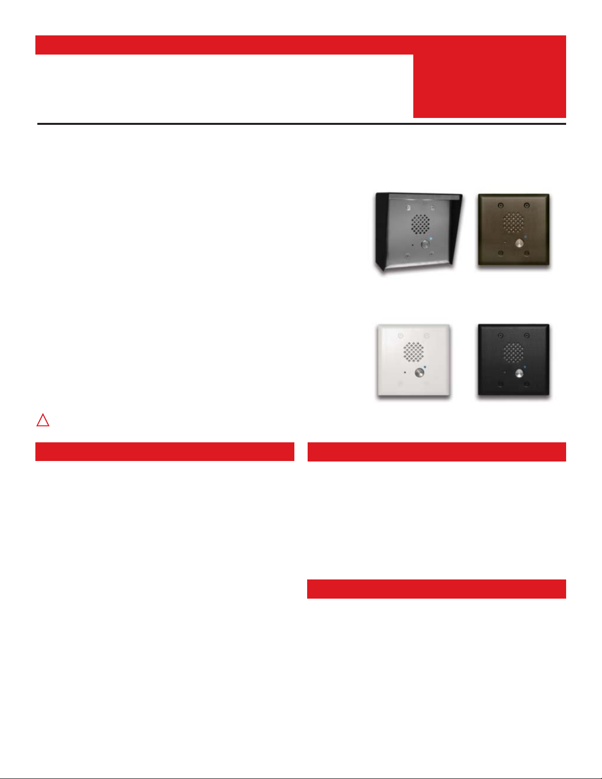
E-60-SS-IP
“Brushed Stainless Steel”
(similar to brushed nickel)
Shown with optional VE-5x5 surface
mount box & VE-LIGHT (not included)
E-60-BN-IP
“Oil Rubbed Bronze”
(satin dark brown powder
paint with fine copper metallic)
E-60-WH-IP
“White”
(satin white powder paint)
E-60-BK-IP
“Black”
(fine texture black powder paint)
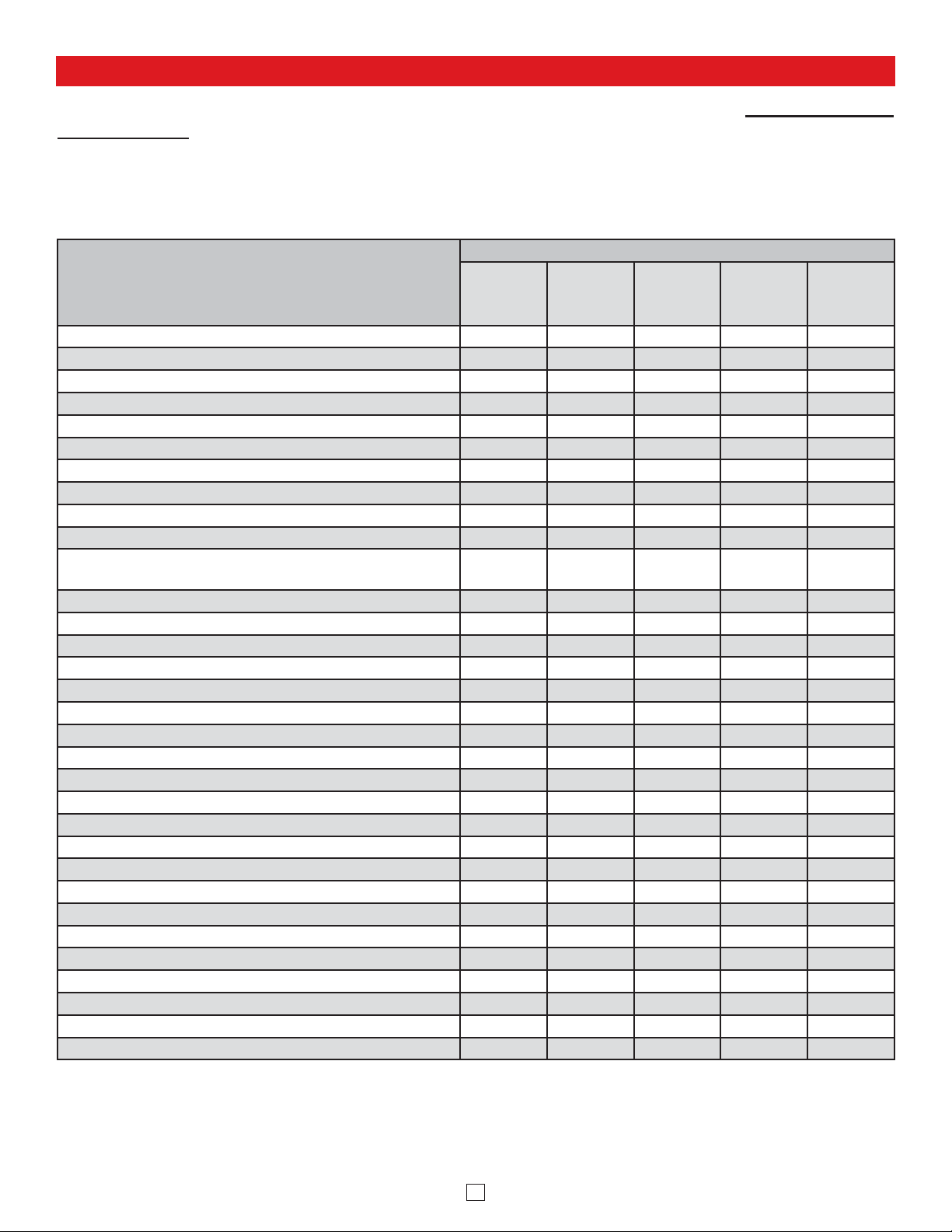
Viking VoIP SIP System Compatibility List
NOTE: Exclusion from this list means only that compatibility has not been verified, it does not mean
incompatibility.
2
For detailed configuration instructions for certain vendors below, see Configuring Viking VoIP Phone
and SIP Servers, DOD# 944.
Vendor
Infrastructure Class
Softswitch
PBX Proxy
SBC
(session border
controller)
Service
Provider
3COM VCX X
3CX X
Aastra X
Asterisk X
Atcom X
Avaya IP Office X
BlueBox X
Brekeke X
Callcentric X
Cisco Unified Communications Manager (CUCM) X X
Cisco Unified Communications Manager Express
(CUCME)
XX
Freeswitch X
Grandstream X
Interactive Intelligence X X
iptel.org X
Kamailio X X
MetaSwitch XX
NEC X
OfficeSIP X
OpenSIPS X
Panasonic (with SIP Extension Card) X
Samsung Communications Manager (SCM) X X
ShoreTel X
Siemens Communications Server (SCS) X
SIP Express Router (SER) X X
sip.antisip.com X
Snom PBX X
Sonus X
Switchvox X X
Teksip X
Toshiba X
VoIP.ms X

Definitions
3
Client: A computer or device that makes use of a server. As an example, the client might request a particular file from the server.
DHCP: Dynamic Host Configuration Protocol. In this procedure the network server or router takes note of a client’s MAC address and
assigns an IP address to allow the client to communicate with other devices on the network.
DNS Server: A DNS (Domain Name System) server translates domain names (ie: www.vikingelectronics.com) into an IP address.
Ethernet: Ethernet is the most commonly used LAN
technology. An Ethernet Local Area Network typically uses twisted pair wires to
achieve transmission speeds up to 1Gbps.
Host: A computer or device connected to a network.
Host Name: A host name is a label assigned to a device connected to a computer network that is used to identify the device in various
forms of network communication.
Hosts File: A file stored in a computer that lists host names and their corresponding IP addresses with the purpose of mapping addresses
to hosts or vice versa.
Internet: A worldwide system of computer networks running on IP
protocol which can be accessed by individual computers or networks.
IP: Internet Protocol is the set of communications conventions that govern the way computers communicate on networks and on the Internet.
IP Address: This is the address that uniquely identifies a host on a network.
LAN: Local Area Network. A LAN is a network connecting computers and other devices within an office or building.
Lease: The amount of time a DHCP
server reserves an address it has assigned. If the address isn’t used by the host for a period of
time, the lease can expire and the address can be assigned to another host.
MAC Address: MAC stands for Media Access Control. A MAC address, also called a hardware address or physical address, is a unique
address assigned to a device at the factory. It resides in the device’s memory and is used by routers to send network traffic to the correct
IP address. You can find the MAC address of your E-60-IP phone printed on a white label on the top surface of the PoE LAN port.
Router: A device that forwards data from one network to another. In order to send information to the right location, routers look at IP Ad
-
dress, MAC Address and Subnet Mask.
RTP: Real-Time Transport Protocol is an Internet protocol standard that specifies a way for programs to manage the real-time transmission
of multimedia data over either unicast or multicast network services.
Server: A computer or device that fulfills requests from a client. This could involve the server sending a particular file requested by the
client.
Session Initiation Protocol (SIP): Is a signaling communications protocol, widely used for controlling multimedia communication sessions
such as voice and video calls over Internet Protocol (IP
) networks. The protocol defines the messages that are sent between endpoints,
which govern establishment, termination and other essential elements of a call.
Static IP Address: A static IP Address has been assigned manually and is permanent until it is manually removed. It is not subject to the
Lease
limitations of a Dynamic IP Address assigned by the DHCP Server. The default static IP Address is: 192.168.154.1
Subnet: A portion of a network that shares a common address component. On TCP/IP networks, subnets are defined as all devices
whose IP addresses have the same prefix. For example, all devices with IP addresses
that start with 100.100.100. would be part of the
same subnet. Dividing a network into subnets is useful for both security and performance reasons. IP networks are divided using a subnet
mask.
TCP/IP: Transmission Control Protocol/Internet Protocol is the suite of communications protocols used to connect hosts on the Internet.
TCP/IP uses several protocols, the two main ones being TCP and IP. TCP/IP is built into the UNIX operating system and is used by the
Internet, making it the de facto standard for transmitting data over networks.
TISP: Telephone Internet Service Provider
WAN: Wide Area Network. A WAN is a network comprising a large geographical area like a state or country. The largest WAN is the In
-
ternet.
Wireless Access Point (AP): A device that allows wireless devices to connect to a wired network using Wi-Fi, or related standards. The
AP usually connects to a router (via a wired network) as a standalone device, but it can also be an integral component of the router itself.
Wireless Repeater (Wireless Range Extender): takes an existing signal from a wireless router or access point and rebroadcasts it to
create a second network. When two or more hosts have to be connected with one another over the IEEE 802.11 protocol and the distance
is too long for a direct connection to be established, a wireless repeater is used to bridge the gap.
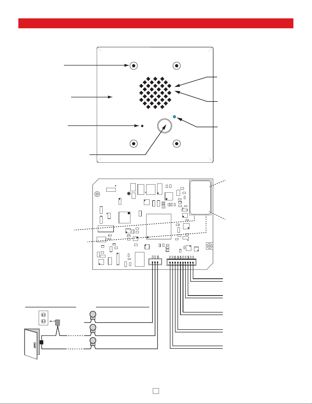
Features Overview
Mounting Screws: (4) 6-32 x
Note: The gel-filled (water-tight) butt connectors are designed for insulation displacement on 19-26 gauge wire with a maximum insulation of 0.082 inches. Cut off stripped wire ends before terminating.
4
3/4" Marine grade 316 stainless
steel, flat head, 5/64" hexdrive
screws (included).
Front View of the E-60-IP Entry Phone
Faceplate Material: 18 gauge
304 stainless steel. The SS model
has a #4 brushed finish, the BK,
BN and WH models have a
powder painted finish.
Microphone: Omni-directional
microphone with protective
water-resistant cloth.
Push Button Switch: Push to
initiate call, push again to
disconnect. Solid 316 stainless
steel internally sealed per IP67.
Green Unit Status LED
Yellow Network Status LED:
Lights steady to indicate power
and data link. Blinks to indicate
network activity.
Rear (PCB) View of E-60-IP Entry Phone
asdesaxtff
Speaker: Mylar speaker with
rubber gasket to maintain
water-tight seal and eliminate
water deterioration.
Speaker Screen: Speaker
screen with 0.018" wide slots to
prevent punctures from
paperclips, etc.
Blue Call LED: Lights steady to
help locate the button in low light,
flashes during dialing, then lights
steady when answered.
18E80FXXXXXX
MAC:
PoE LAN Port 10/100, PoE
Class 1 (<4 Watts): Connect
to your LAN via RJ45 plug
and CAT5 or greater twisted
pair wire.
MAC Address Label: The
MAC address is aunique 12
digit number used by routers
to send network traffic to the
correct IP address.
Connect to Optional
Doorstrike, Mag Lock,
Gate Controller, etc.
120V AC
(not
connected)
Doorstrike /
Magnetic Lock
(Power typically not
required for gate controllers)
Optional 2 Amp Relay
Output Contacts
(2A@30VDC/ 250VAC max)
N.C. (Gray)
COM. (Blue)
N.O. (Yellow)
3 Gel-Filled Butt
Connectors (included)
- Black
+ Red
Black
Black
White
White
- Black
+ Red
LED
Help Switch
Red
Info Switch (optional)
Red
Speaker
Microphone
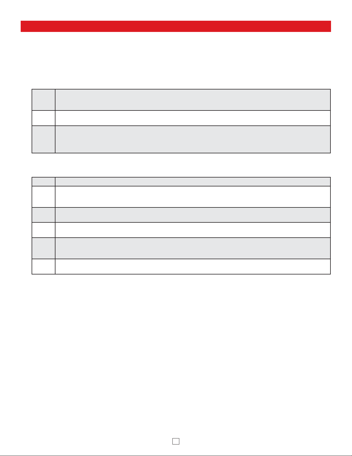
Installation
The E-60-IP is designed to be flush mounted into a standard double gang rough-in box with minimum inside dimensions of
2.25” deep x 3.65” wide x 2.84” tall. The E-60-IP can also be surface mounted using a Viking VE-5x5 for mounting to a wall,
post or Viking model VE-GNP gooseneck pedestal, EWP model recommended (not included, see DOD# 424). WARNING:
Do NOT use a typical “wet location box” as not all styles seal properly with the E-60-IP faceplate.
Step 1.
Front of box should stick out approximately ½" from front surface of wall stud (this may vary depending on the walls
sheathing and siding thickness). Caution: Rough-In box must be mounted LEVEL and must NOT stick out beyond the
front surface of siding.
Step 2.
To maintain a vapor barrier on outside wall applications (EWP model), caulk around the box, filling any gaps between
the box and the rough opening. Apply caulk to any holes in the box around wires, etc.
Step 3.
When installing siding cut a hole just large enough for the Rough-In box opening. Caution: Too large of a hole can cause
plate misalignment and compromise the gasket seal. Note: When mounting to 4 inch or less horizontal lap siding, a
siding mounting block can be used. Contact siding installer for the correct mounting block. Note: A side mounting block
is recommended when mounting to vinyl siding.
Step 1. Make sure mounting location is free of wall studs, wires, etc.
Step 2.
Place rough-in box LEVEL against siding. Trace outline of box onto siding. Note: When mounting to 4 inch or less horizontal lap siding, a siding mounting block can be used. Contact your siding Installer for the correct mounting block part
number. Note: A siding mounting block is recommended when mounting to vinyl siding.
Step 3.
Cut a hole through the siding and wall sheathing just large enough for the rough-in box. Caution: Too large of a hole can
cause plate misalignment and compromise the gasket seal.
Step 4.
The front surface of the Rough-In box can be mounted flush against wood siding or can be recessed and mounted flush
against wall sheathing when mounting on aluminum, steel or vinyl siding.
Step 5.
When mounting to 5/8 inch thick or less wall sheathing the two attached screws with wing brackets can be used to secure
the rough-in box. When mounting to surfaces thicker than 5/8 inch, four standard flat head dry wall screws can be used
to secure the Rough-In box through its mounting ears.
Step 6.
To maintain a vapor barrier on outside wall applications (EWP model), caulk around the box, filling any gaps between
the box and the rough opening. Apply caulk to any holes in the box around wires, etc.
A. New Construction Flush Mounting
B. Old Work / Remodel Flush Mounting (Using an Allied Molded 9312 Rough-In Box)
A Viking model VE-5x5 can be used to surface mount an E-60-IP to a wall, post or Viking model VE-GNP Gooseneck
Pedestal (EWP model recommended), see DOD# 424 for more information on the VE-5x5 and VE-GNP. Drill a small
wire exit hole in wall. Pull wire through and seal hole around wire with putty or caulking. Route wire into the VE-5x5
box, securely screw it to wall or post and seal hole in box around wire with putty or caulking. Attach (2) junction box to
double gang adapter plates (included with E-60-IP) to top and bottom holes of the VE-5x5 prior to mounting the E-60-
IP. Note: Conduit may also be used when surface mounting wire, but should not enter through the top of the VE-5x5.
When routing wiring from above, a drip loop is required. WARNING: Do NOT use a typical “wet location box” as not all
styles seal properly with the E-60-IP faceplate.
C. Surface Mounting
5
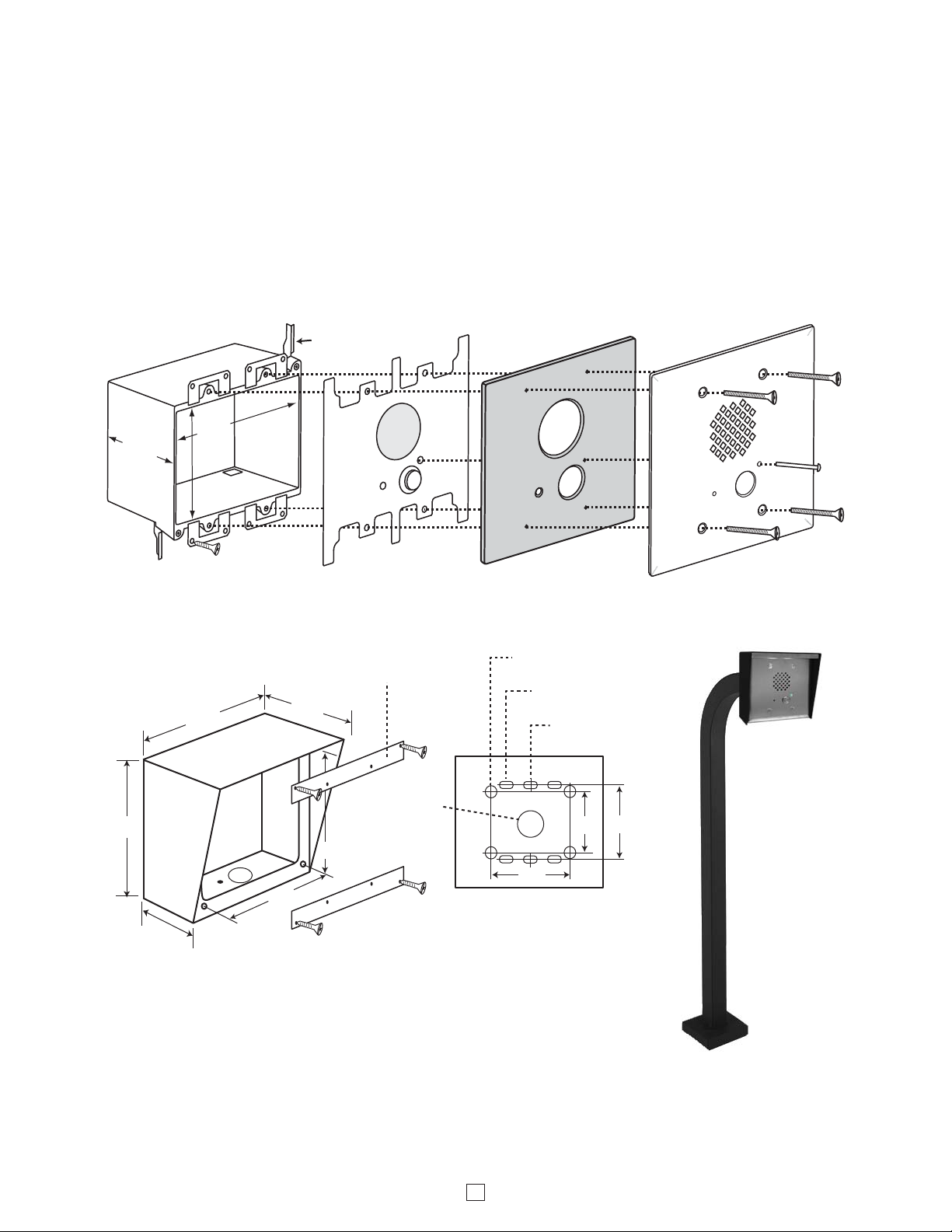
After the rough-in box or VE-5x5 is securely mounted, caulking between the box and rough opening is completed (if required), and wires are connected, remove paper liner from faceplate gasket. While firmly holding the LED light pipe in
the faceplate, carefully slide the faceplate gasket over the back of the light pipe and press gasket to the back of the
faceplate. Push the 1-1/4" 6-32 screws through faceplate holes and small holes in gasket, the faceplate gasket should
retain the screws. Position circuit board mounting plate over screws. Align screws with double gang box bosses and
tighten face plate until gasket is fully collapsed and the push button is protruding through the clearance hole in the face
plate. Included 1/4" thick gasket will provide an adequate seal for most siding surfaces; however for rough surfaces (ie:
brick, stucco, etc.) additional caulking may be required.
D. Mounting the Faceplate
* CAUTION: Excessive wire length and/or using a rough-in box with inadequate depth can apply force to the circuit board causing
physical damage.
** IMPORTANT: Push LED light pipe into faceplate hole, then place faceplate upside down on a clean flat surface and push down
on back side of plate until light pipe is fully seated and straight. WARNING: Inserting the light pipe more than one time can cause
a loose fit.
6
"Old Work" Double Gang
Rough-In Box (Allied Molded
9312 box shown, not included)
WARNING: Do NOT use a wet
*2.25"
deep
min.
location box.
3.65"
wide
min.
2.84"
tall min.
Circuit Board
Mounting Plate
(included)
1/4" Thick Foam
Faceplate Gasket
(included)
Facplate
(included)
Light Pipe
(included)
** LED
(4) Optional Dry Wall
Screws (not included)
|
OR
|
5.22”
5.14”
2.25”
Optional VE-5x5 Surface Mount Box with
black satin powder paint finish, not included
(DOD# 424). Optional VE-LIGHT kit can be
used to illuminate the faceplate when used
with a VE-5x5 (DOD# 428).
WARNING: Do NOT use a wet location box.
(2) Junction Box to Double Gang
Adapter Plates and (4) 5/64 Hex
Drive Flat Head Screws
(included with the E-60-IP)
3.25”
3.63”
3.63”
(4) 0.38” diameter holes
for gooseneck mounting
(4) 0.2 x 0.43 slots
for double gang box
(2) 0.2 x 0.43 slots
for single gang box
(1) .74"
diameter
3.0” 3.3”
3.0”
Rear View of VE-5x5
Surface Mount Box
(not included)
The optional VE-5x5 Surface Mount Box
(above) is designed to be surface mounted
to a single gang box, double gang box or
VE-GNP Gooseneck Pedestal (shown right).
For more information on the VE-5x5 and
VE-GNP, see DOD# 424.
(4) 6-32 x 1.25" Long 5/64"
Hexdrive Flathead Screws
(included)
Model E-60-SS-IP
shown in an optional
VE-5x5 Surface
Mount Box and
VE-LIGHT mounted
to a VE-GNP
Gooseneck Pedestal
Other pedestal
options available,
see DOD# 424
 Loading...