

Viking E-35-IP Product Manual
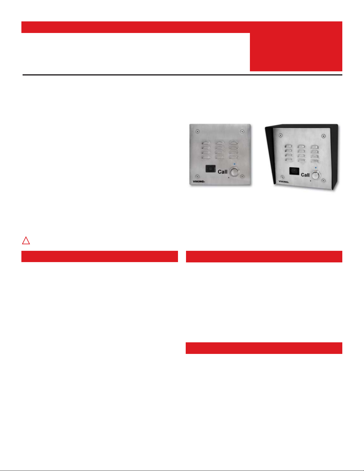
The E-35-IP VoIP Entry Phone is designed to provide quick
and reliable handsfree communication for SIP VoIP phone
systems with PoE. The E-35-IP Entry Phone can be programmed from any Touch Tone phone or PC on the same
LAN. The Entry phone can dial up to 5 programmable numbers and provide color analog CCTV video of who is at your
door or gate.
The E-35-IP Entry Phone will flash the “Call” LED during dialing and automatically light the LED when the call is answered. All programming parameters, including phone
numbers and location numbers, are stored in non-volatile
memory, requiring no batteries. The unit is PoE powered.
For outdoor installations where the unit is exposed to precipitation or condensation, the E-35-IP Entry Phones are available
with Enhanced Weather Protection (EWP). EWP products feature foam rubber gaskets and boots, sealed connections, gelfilled butt connectors, as well as urethane or thermal plastic potted circuit boards. For more information, see DOD# 859.
PRODUCT MANUAL
Designed, Manufactured and Supported in the USA
COMMUNICATION & SECURITY SOLUTIONS
E-35-IP/EWP
VoIP Entry Phones with
Analog Color Video Camera
September 21, 2015
VIKING
Features
Applications
Specifications
www.vikingelectronics.com
Information: (715) 386-8861
VoIP Entry Phones with
Built-In Analog Color Video Camera
• Built-In high resolution analog NTSC color video camera with wide viewing angle,
tilt/swivel adjustments and wide operating temperature
• Self diagnostic reports via email (testing com, mic, speaker & switch)
• Automatic polling and programming software included
• 2 Amp relay contacts for door/gate or SL-2 strobe light control
• Blue “Call” LED indicator
• SIP compliant (see pg 2 for list of compatible IP-PBX phone systems)
• PoE powered (class 1, <4 watts)
• Automatic Noise Canceling (ANC) feature for proper operation in noisy environments
• VoIP eliminates the need for “Push to Talk” mode
• Network downloadable firmware
• T-10 Torx security screws for added security
• Handsfree operation
• Marine grade 316 stainless steel prevents corrosion
• Laser Etched graphics on stainless steel models
• Programmable to dial up to 5 numbers on busy or ring no answer
• Cycles through backup phone numbers on busy or no-answer
• Optional Enhanced Weather Protection (EWP), EWP products are designed to meet
IP66 Ingress Protection Rating, see DOD# 859
• Hangs up on busy signal, time-out or touch tone command
• Remotely programmable
• Extended temperature range (-40°F to 140°F)
• Replacement board available
• Volume adjustments for microphone and speaker
• E-35-IP is flush mountable using the included rough-in box or can be surface mounted
using an optional VE-5x5 Surface Mount Box (DOD# 424)
• Optional PB-100 Polling System available (DOD# 232)
• Optional SL-2 or BLK-4-EWP strobe light kit available (DOD# 242/653)
Power: PoE class 1 (<4 watts)
Dimensions: Overall-127mm x 127mm x 57mm (5” x 5” x 2.25”),
Plastic Electrical Box-102mm x 102mm x 54mm (4” x 4” x 2.12”)
Shipping Weight: 0.9 Kg (2 lbs)
Operating Temperature: -40° C to 60° C (-40°F to 140°F)
Humidity - Standard Products: 5% to 95% non-condensing
Humidity - EWP Products: Up to 100%
Audio Codecs: G711u, G711a, G722
Network Compliance: IEEE 802.3 af PoE, SIP 2.0 RFC3261,
100BASE-TX with auto cross over
Connections: (1) RJ45 10/100 Base-T, (6) gel-filled butt connectors (3M Scotchlok UR2)
(See page 3 for camera specifications)
Installation requires the assistance of a Network Administrator / IT Technician.
!
• Gate Entrance
• Parking ramps/lots
• ATM machines
• Medical centers
• Lobbies
• Entryways
• Stadiums
• Convention centers
• Public access areas
Standard
Flush Mount
Shown in Optional
VE-5x5 Surface Mount Box
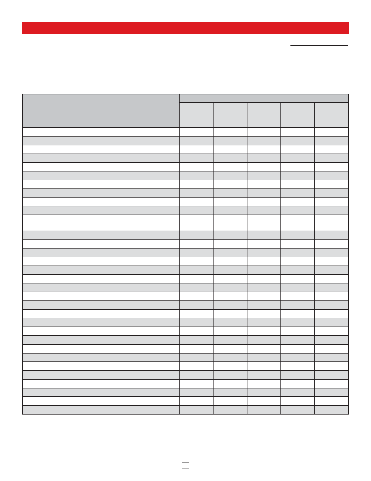
Viking VoIP SIP System Compatibility List
NOTE: Exclusion from this list means only that compatibility has not been verified, it does not mean
incompatibility.
For detailed configuration instructions for certain vendors below, see Configuring Viking VoIP Phone
and SIP Servers, DOD# 944.
2
Vendor
Infrastructure Class
Softswitch
PBX Proxy
SBC
(session border
controller)
Service
Provider
3COM VCX X
3CX X
Aastra X
Asterisk X
Atcom X
Avaya IP Office X
BlueBox X
Brekeke X
Callcentric X
Cisco Unified Communications Manager (CUCM) X X
Cisco Unified Communications Manager Express
(CUCME)
XX
Freeswitch X
Grandstream X
Interactive Intelligence X X
iptel.org X
Kamailio X X
MetaSwitch XX
NEC X
OfficeSIP X
OpenSIPS X
Panasonic (with SIP Extension Card) X
Samsung Communications Manager (SCM) X X
ShoreTel X
Siemens Communications Server (SCS) X
SIP Express Router (SER) X X
sip.antisip.com X
Snom PBX X
Sonus X
Switchvox X X
Teksip X
Toshiba X
VoIP.ms X
Definitions
Power: 6-22V DC 150mA (12V DC UL Listed adapter included)
Image Sensor: 1/4” color CMOS
Video Output: 1 VP-P composite, NTSC, 75 ohms
Resolution: 420 lines (640 x 480 @ 30fps / 307,200 pixels)
Sensitivity: 0.025 LUX (50 IRE) F 1.2 3200K
Lens: 2.1mm, conical pinhole
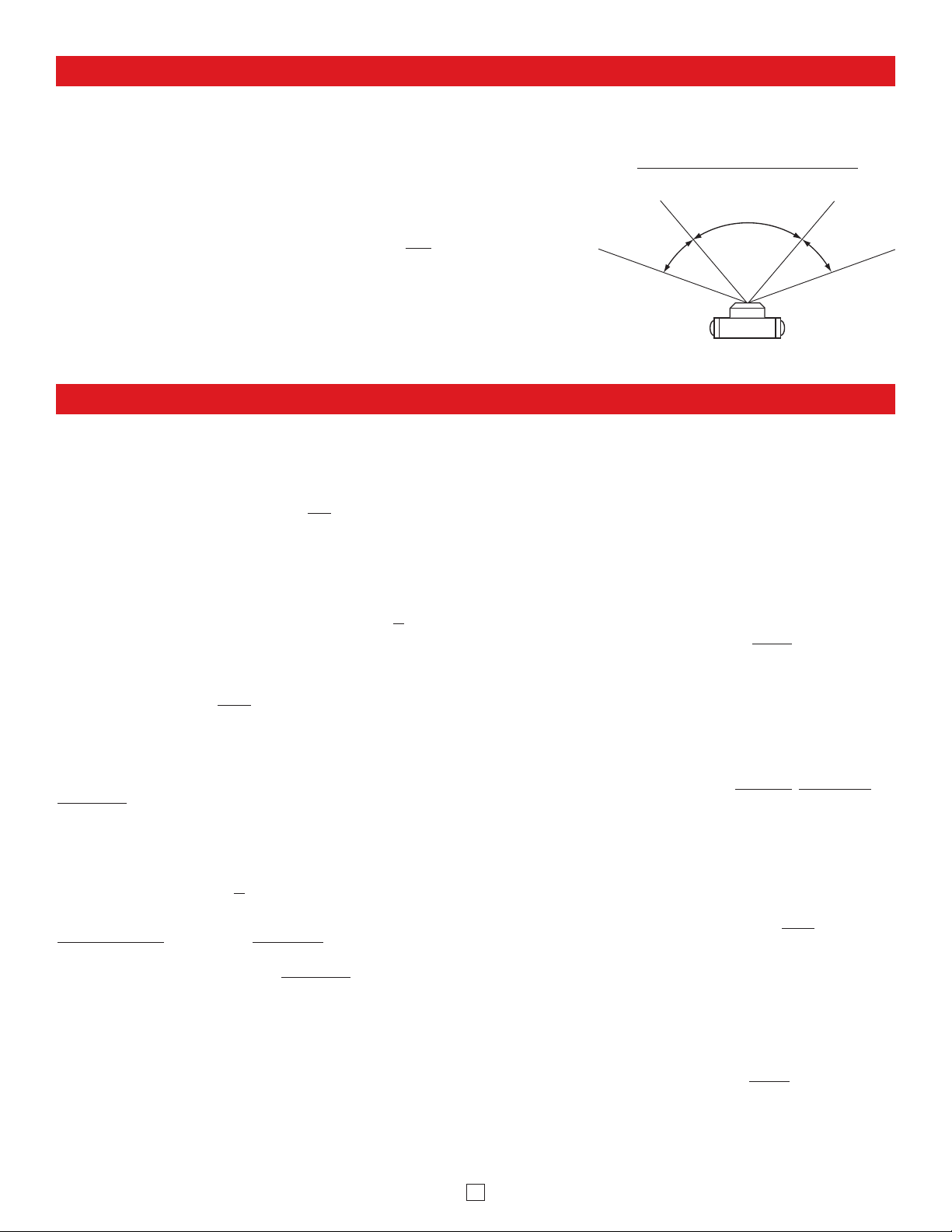
FOV (Field of View): 80° Horizontal, 60° Vertical, 100° Diagonal
Tilt/Swivel Adjustment: Vertical +/- 20°, horizontal +/- 30° (see Diagram A)
IR Compatibility: This camera is equipped with an OLP (Optical Low Pass) filter to maintain cor-
rect video color in outside applications. The standard camera is NOT
compatible with IR illumina-
tors. If IR illumination is required, you will need to replace the existing camera with a Viking model
VCAM-1IR. For more information, see DOD# 190.
Maximum Wire Run Length: 1000 ft with *RG59/RG6 for video and CAT5 for power (1 pair) and
entry phone audio (1 pair). 150 ft with CAT5E for video, power and entry phone audio (longer
video runs are possible by using video balun transceivers, see Installation C, 2, page 5).
* Note: RG59 or RG6 with solid center conductor and 95% bare copper braid shield.
80° Lens FOV
Rotate
Left 30°
Rotate
Right 30°
Camera Lens
Diagram A
Camera Horizontal Field of View:
Camera Specifications
3
Client: A computer or device that makes use of a server. As an example, the client might request a particular file from the server.
DHCP: Dynamic Host Configuration Protocol. In this procedure the network server or router takes note of a client’s MAC address and assigns an IP address to
allow the client to communicate with other devices on the network.
DNS Server: A DNS (Domain Name System) server translates domain names (ie: www.vikingelectronics.com) into an IP address.
Ethernet: Ethernet is the most commonly used LAN
technology. An ethernet Local Area Network typically uses twisted pair wires to achieve transmission speeds
up to 1Gbps.
Host: A computer or device connected to a network.
Host Name: A host name is a label assigned to a device connected to a computer network that is used to identify the device in various forms of network commu-
nication.
Hosts File: A file stored in a computer that lists host names and their corresponding IP addresses with the purpose of mapping addresses to hosts or vice versa.
Internet: A worldwide system of computer networks running on IP protocol which can be accessed by individual computers or networks.
IP: Internet Protocol is the set of communications conventions that govern the way computers communicate on networks and on the Internet
.
IP Address: This is the address that uniquely identifies a host on a network.
LAN: Local Area Network. A LAN is a network connecting computers and other devices within an office or building.
Lease: The amount of time a DHCP server reserves an address it has assigned. If the address isn’t used by the host for a period of time, the lease can expire
and the address can be assigned to another host.
MAC Address: MAC stands for Media Access Control. A MAC address, also called a hardware address or physical address, is a unique address assigned to a
device at the factory. It resides in the device’s memory and is used by routers to send network traffic to the correct IP address. You can find the MAC address of
your E-35-IP phone printed on a white label on the top surface of the PoE LAN port.
Router: A device that forwards data from one network to another. In order to send information to the right location, routers look at IP Address, MAC Address and
Subnet Mask
.
RTP: Real-Time Transport Protocol is an Internet protocol standard that specifies a way for programs to manage the real-time transmission of multimedia data
over either unicast or multicast network services.
Server: A computer or device that fulfills requests from a client. This could involve the server sending a particular file requested by the client.
Session Initiation Protocol (SIP): Is a signaling communications protocol, widely used for controlling multimedia communication sessions such as voice and
video calls over Internet Protocol (IP
) networks. The protocol defines the messages that are sent between endpoints, which govern establishment, termination and
other essential elements of a call.
Static IP Address: A static IP Address has been assigned manually and is permanent until it is manually removed. It is not subject to the Lease limitations of a
Dynamic IP Address
assigned by the DHCP Server. The default static IP Address is: 192.168.154.1
Subnet: A portion of a network that shares a common address component. On TCP/IP networks, subnets are defined as all devices whose IP addresses have the
same prefix. For example, all devices with IP addresses that start with 100.100.100. would be part of the same subnet. Dividing a network into subnets is useful
for both security and performance reasons. IP networks are divided using a subnet mask.
TCP/IP: Transmission Control Protocol/Internet Protocol is the suite of communications protocols used to connect hosts on the Internet. TCP/IP uses several protocols, the two main ones being TCP and IP. TCP/IP is built into the UNIX operating system and is used by the Internet, making it the de facto standard for transmitting data over networks.
TISP: Telephone Internet Service Provider
WAN: Wide Area Network. A WAN is a network comprising a large geographical area like a state or country. The largest WAN is the Internet.
Wireless Access Point (AP): A device that allows wireless devices to connect to a wired network using Wi-Fi, or related standards. The AP usually connects to
a router (via a wired network) as a standalone device, but it can also be an integral component of the router itself.
Wireless Repeater (Wireless Range Extender): takes an existing signal from a wireless router or access point and rebroadcasts it to create a second network.
When two or more hosts have to be connected with one another over the IEEE 802.11 protocol and the distance is too long for a direct connection to be established,
a wireless repeater is used to bridge the gap.
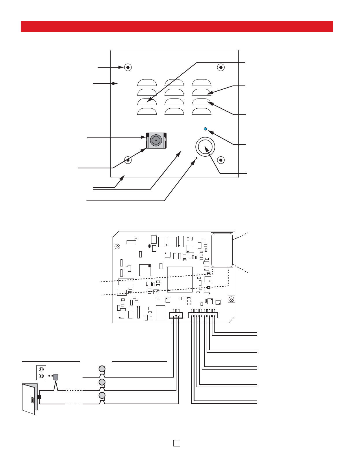
Features Overview
Note: The gel-filled (water-tight) butt connectors are designed for insulation displacement on 19-26 gauge wire with a maximum insulation of 0.082 inches. Cut off stripped wire ends before terminating.
4
Mounting Screws:
(4) 6-32 X
3/4” Marine grade 316 stainless
steel, flat head, T-10 Torx security
screws and drive bit (included)
Faceplate: 14 gauge Marine grade
316 stainless steel faceplate
with #4 brushed finish.
Color Video Camera: Wide
operating temperature range of
-30°F to 150°F, NTSC composite
video output with 420 lines of
resolution, 70° wide viewing angle
lens, tilt and swivel adjustments
for aiming towards visitors.
Protective Camera Window:
Impact resistant polycarbonate
lens with scratch resistant coating
and water-tight gasket.
Laser Etched Graphics: For long
lasting easy to read graphics.
Condensation Drain Hole
Front View of the E-35-IP Entry Phone
Call
VIKING©
Microphone: Omni-directional
microphone with protective
water-resistant cloth.
Speaker: Mylar speaker with
rubber gasket to maintain
water-tight seal and eliminate
water deterioration.
Speaker Screen: Stainless steel
speaker screen with 0.018"
diameter holes to prevent
punctures from paperclips, etc.
Blue LED: Lights steady to help
locate the button in low light,
flashes during dialing, then lights
steady when answered.
Push Button Switch: Push to
initiate call, push again to
disconnect. Solid 316 stainless
steel internally sealed per IP67.
Green Unit Status LED
Yellow Network Status LED:
Lights steady to indicate power
and data link. Blinks to indicate
network activity.
Connect to Optional
Doorstrike, Mag Lock,
Gate Controller, etc.
120V AC
(not
connected)
Doorstrike /
Magnetic Lock
(Power typically not
required for gate controllers)
Rear (PCB) View of E-35-IP Entry Phone
Optional 2 Amp Relay
Output Contacts
(2A@30VDC/ 250VAC max)
N.C. (Gray)
COM. (Blue)
N.O. (Yellow)
3 Gel-Filled Butt
Connectors (included)
18E80FXXXXXX
asdesaxtff
MAC:
- Black
+ Red
Black
Black
White
White
- Black
+ Red
PoE LAN Port 10/100, PoE
Class 1 (<4 Watts): Connect to
your LAN via RJ45 plug and CAT5
or greater twisted pair wire.
MAC Address Label: The MAC
address is a unique 12 digit
number used by routers to send
network traffic to the correct IP
address.
LED
Help Switch
Red
Info Switch (optional)
Red
Speaker
Microphone
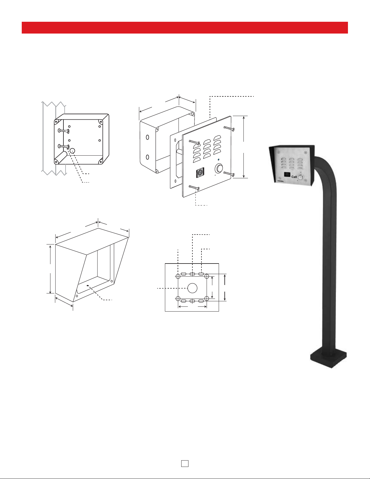
Installation
A. Mounting the E-35-IP
The E-35-IP is designed to be flush mounted to the included 4” x 4” x 2” deep plastic rough in box or surface mounted
using an optional Viking model VE-5x5. Important: The E-35-IP will NOT mount to a standard double gang box. The
plastic rough in box (part # 259576) may be purchased separately. Go to www.vikingelectronics.com and click on
“Spare Parts”.
5
5.14”
Front View of
Plastic Rough-In
Box (included)
Wall Stud
5.22”
2.25”
Front View of Optional
VE-5x5 (not included)
Wire knock out
(2) Standard flat head
dry wall (sheet rock)
screws (not included)
3.25”
Condensation
Drain Hole
4.0"
(4) 0.38” diameter
(for gooseneck
pedestal mounting)
(1) 0.74"
diameter
VE-5x5 (not included)
2.1”
©
VIKING
3.0”
Rear View of
Peel paper liner and adhere gasket
to back of panel, centering over
mounting holes. Caution: For rough
surfaces (ie: brick, stucco, etc.)
additional caulking may be required.
5.0”
Typical
Call
(4) 6-32 X 3/4” Marine grade 316
stainless steel, flat head, T-10 Torx
security screws and drive bit (included)
(2) 0.2 x 0.43 slots for
single gang box
(4) 0.2 x 0.43 slots for
double gang box
Model E-35-IP shown
in an optional VE-5x5
Surface Mount Box
mounted to a
3.0” 3.3”
VE-GNP Gooseneck
Pedestal
Other pedestal
options available,
see DOD# 424
Optional VE-5x5 Surface Mount Box with
black satin powder paint finish, not included
(DOD# 424). Optional VE-LIGHT kit can be
used to illuminate the faceplate when used
with a VE-5x5 (DOD# 428).
WARNING: Do NOT use a wet location box.
The optional VE-5x5 Surface Mount Box
(above) is designed to be surface mounted
to a single gang box, double gang box or
VE-GNP Gooseneck Pedestal (shown right).
For more information on the VE-5x5 and
VE-GNP, see DOD# 424.
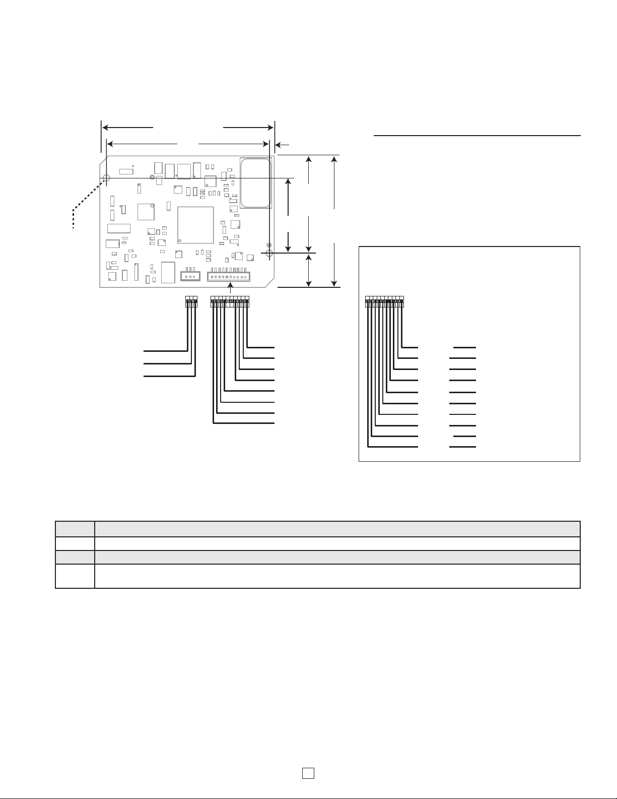
B. Replacement IP Board Kit (Model E-1600-53A-IP)
This is a board (PCB) only kit, no chassis is included. This kit can be used to convert any Viking E-35 analog phone to
a VoIP version. The kit can also be used to replace a damaged IP board in the field. This kit comes in standard and
EWP version. The optional EWP version features foam rubber gaskets and boots, sealed connections, gel-filled butt
connectors, as well as urethane or thermal plastic potted circuit boards, see DOD# 859 for more information.
Step 1. Cut wires from J1 (10 pin connector) and J2 (2 pin connector).
Step 2. Remove the two #6 phillips screws fastening the circuit board.
Step 3. Cut off any stripped wire ends from the replacement cable.
Step 4.
Using the supplied gel-filled butt connectors, connect corresponding wires from replacement cable to the previously cut
wires from the LED, Call switch, Speaker and Microphone. See FIGURE 1 above for wire color and polarity.
How to Replace Analog E-35 or E-35-EWP Circuit Boards:
E-1600-53A-IP Board Specifications
Shipping Weight: .45 kg (1 lb)
Connections: (1) RJ45 10/100 Base-T, (3)
optional gel-filled butt connectors, (10) additional gel-filled butt connectors included with
EWP version only.
Note: The gel-filled (water-tight) butt connectors are designed for insulation displacement on 19-26 gauge wire with a maximum insulation of 0.082 inches. Cut off stripped wire ends before terminating.
** Note: These two red wires are only used on units with an Info button. When
installing on a single button unit, cut off these two red wires and discard.
6
3.50 (3.58 EWP)
(2) 0.156
diameter
type 2
mounting
holes
Optional 2 Amp Relay
Output Contacts Connector
Connect to doorstrike,
mag lock, gate controller, etc.
Gray (N.C.)
Blue (COM)
Yellow (N.O.)
3.20
10 1
31
18E80FXXXXXX
asdesaxtff
Connector and Wires
from Existing Standard
E-35 Analog
Entry Phone
0.15 (0.19 EWP)
MAC:
1.5
0.63
(0.67
EWP
Black
Red
Black
Black
White
White
Black
Red
2.0
(2.04
EWP)
2.63
(2.71
EWP)
- OR -
FIGURE 1
Replacement Cable Assembly (included )
Replacement connectors, wires and
butt connectors for use when replacing
E-35-EWP analog circuit boards.
- Black
+ Red
Black
Black
Red**
Red**
White
White
- Black
+ Red
LED
Call Switch
Info Switch
Speaker
Mic
(not used)
 Loading...