


PRODUCT MANUAL
Designed, Manufactured and Supported in the USA
SECURITY & COMMUNICATION SOLUTIONS
Provide Reliable and Intelligent
Communication In Noisier Locations
Features
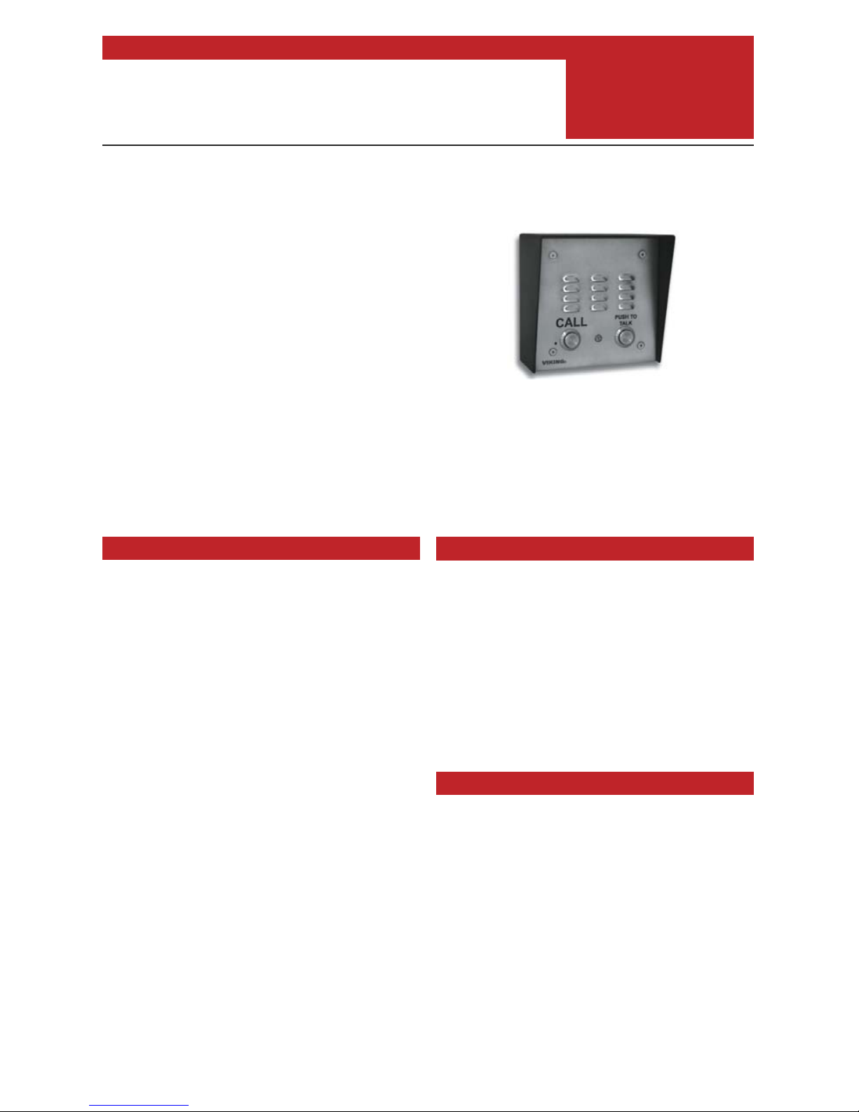
The E-30-PT is designed to provide quick and reliable
communication in noisier areas. The mic sensitivity is set
to a low level until the TALK button is pressed then it is
raised to a normal level. In this way, the E-30-PT assures
that the called party’s voice will be broadcast over the
speaker. In applications where the background noise
can be louder than the person calling, a handset type
phone is recommended.
The E-30-PT features non-volatile memory, a built in
dialer, and intelligent call progress detection for automatic
hang-up when the call is completed. The E-30-PT can be
programmed to dial up to 5 different numbers on ring no
answer or busy and can be configured to dial these
numbers until answered.
The E-30-PT-EWP shares all of the features of the
E-30-PT in addition to Enhanced Weather Protection
(EWP) for outdoor installations where the unit is exposed
to precipitation or condensation. EWP products feature
foam rubber gaskets and boots, silicon sealed
connections, gel-filled butt connectors, as well as
urethane or thermal plastic potted circuit boards with
internally sealed, field-adjustable trim pots and DIP
switches for easy on-site programming.
• Vandal Resistant Features: 14 gauge louvered 316
stainless steel faceplate with permanent laser etched
graphics, speaker/mic screen, heavy duty metal “Call”
button and T-10 Torx security mounting screws
• Weather Resistant Features: Marine grade 316
stainless steel faceplate, T-screws and push button
switch. Switch internally sealed per IP67. Mylar
speaker. Self-draining mic mount. Faceplate, mic and
speaker gaskets. Weather resistant powder paint on
optional VE-5x5 (DOD 424).
• E-30-PT-EWP is designed to meet IP66 Ingress
Protection Rating (see DOD 859 for more information)
• Push to talk button
• Telephone line powered
• Non-volatile E
2
memory (no batteries required)
• Programmable to dial up to 5 numbers on busy or ring
no answer
• Blue off-hook LED indicator
• Volume adjustments for microphone and speaker
• Advanced call progress detection: disconnects on
busy signal, return to dial tone, CPC, reorder tone,
maximum call time out and programmable silence
time out
• Selectable auto-answer feature for monitoring
• Selectable push button disconnect
• Extended temperature range (-30°F to 150°F)
• Flush mountable using included plastic rough-in box
• Optional VE-5x5 surface mount back box (DOD 424)
Non-ADA Hot-Line Phones for:
• Terminals • Parking lots/ramps
• Stadiums • Convention centers
• ATM machines
Gate and Door Entry Phones for:
• Business lobbies • Residences
• Vehicular and Pedestrian gates
Power: Telephone line powered. Minimum 24V DC talk
battery voltage, with a minimum loop current of 20mA
loop. Loop current may be boosted on low current lines
with a Viking Model TBB-1B talk battery booster (see
DOD 632).
Minimum Ring Voltage: 90VAC RMS
Dimensions: Overall-5” x 5” x 2.25” (127mm x 127mm x
57mm), Plastic Electrical Box-4” x 4” x 2.12” (102mm x
102mm x 54mm )
Shipping Weight: 2.2 lbs (1 Kg)
Operating Temperature: -30°F to 150°F (-34°C to 65° C)
Humidity - E-30-PT: 5% to 95% non-condensing
Humidity - E-30-PT-EWP: Up to 100% condensing
Connections - E-30-PT: RJ11 jack
Connections - E-30-PT-EWP: Gel-filled butt connectors
E-30-PT/EWP
Speaker Phone with
Push to Talk Button
February 5, 2018
Applications
Specifications
VIKING
E-30-PT/E-30-PT-EWP
Brushed 316 Stainless steel
shown with optional VE-5x5
CAUTION - When installing on an analog extension of a phone
system: Some phone systems do not conform to analog telecom
standards and might not be compatible with the E-30-PT speaker
phones. For a detailed description of the telephone line
specifications required for any of the E-30-PT phones, see DOD#
869.
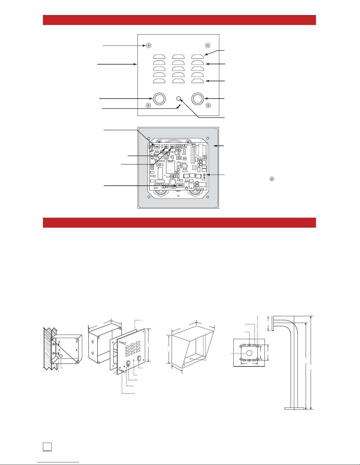
Features Overview
Installation
IMPORTANT: Electronic devices are susceptible to lightning and power station electrical surges from both the AC
outlet and the telephone line. It is recommended that a surge protector be installed to protect against such surges.
Caution: When warm air comes in contact with cold surfaces, such as outside walls, it causes condensation. To help
prevent condensation from accumulating inside the E-30-PT, bring conduit into the bottom of the unit. If this is not
possible, drill a 1/4” diameter hole in the bottom of the plastic rough-in box.
*Note: Peel off paper liner and adhere gasket to the back of the faceplate, centering it over the four corner mounting
holes. Be careful to position the modular jack inside the chassis as not to damage the components on the circuit
board.
A. Mounting
2
1
2
ON
CALL
VIKING
©
PUSH TO TALK BUTTON: Raises microphone
volume to normal level when pressed.
Speaker Screen: Stainless steel speaker
screen with 0.018" diameter holes to prevent
punctures from paperclips, etc.
Faceplate: 14 gauge Marine grade 316
stainless steel faceplate and push button
switch (sealed per IP67).
Speaker: Mylar speaker with rubber gasket to
maintain water-tight seal and eliminate water
deterioration.
Condensation Drain Hole
Mounting Screws: (4) 6-32 x 3/4" Marine
grade 316 stainless steel, flat head, 5/64"
hexdrive, screws (included).
LED: Lights Blue for "In-Use" indication.
Faceplate Gasket: 1/8" thick closed cell PVC
to provide a water-tight seal.
Earth Ground: To increase surge protection,
loosen the screw labeled (as shown) and
fasten a wire with ring terminal (included) from
the mounting screw to Earth Ground (grounding
rod, water pipe, etc.)
Microphone Volume
Speaker Volume
DIP Switches (see page 7):
1: Push Button Feature (connect / disconnect)
2: Auto Answer Feature (on/off)
3: Programming Switch (normal/programming)
Microphone: Omni-directional microphone
with protective water-resistant cloth.
DIP Switches (see page 7):
1: Normal Audio Detection
2: Increased Audio Detection
PUSH TO
TALK
CALL Button: Push to initiate call, push again
to disconnect. Solid 316 stainless steel
internally sealed per IP67.
Front View of Optional
VE-5x5 (not included)
2.25”
Condensation
Drain Hole
5.14”
5.22”
3.25”
Rear View of VE-5x5
(not included)
(4) 0.38” diameter
(for gooseneck mounting)
(4) 0.2 x 0.43 slots
for double gang box
(2) 0.2 x 0.43 slots
for single gang box
(1) .74" dia
3.0” 3.3”
3.0”
Wall Stud
Front View of
Plastic Rough-In
Box (included)
Wire knock out
39.5”
41.41”
3.81”
* Adhere gasket to front panel,
centering over mounting holes
CALL
PUSH TO
TALK
CALL
CONNECTED
4.0"
"Push to Talk"
Button
Call Connected Red LED
"Call" Button
5.0”
2.1”
Marine grade 316 stainless steel faceplate
and push button switches (sealed per IP67)
(4) 6-32 X 3/4” Marine grade 316 stainless steel, flat
head, 5/64" T-10 Torx Security Screws (included)
Side View of
VE-GNP
(not included)
(2) Standard flat head dry wall
(sheet rock) screws (not included)
Condensation
Drain Hole
Important: The E-30-PT will
NOT mount to a standard
double gang box.
Note: The plastic rough-in box (part # 259576) may be purchased separately in advance. Go to
www.vikingelectronics.com and click on “Spare Parts”.
Programming
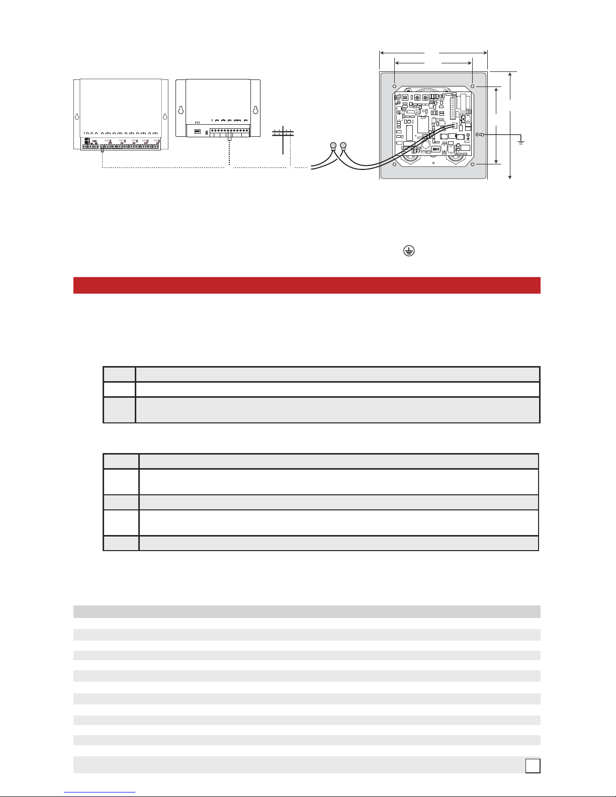
B . Wiring the E-30-PT Phone Board
** Note: The gel-filled (water-tight) butt connectors are designed for insulation displacement on 19-26 guage wire
with a maximum insulation of 0.082 inches. Cut off stripped wire ends prior to terminating.
** * Note: To increase surge protection, loosen the PCB mounting screw labeled (as shown above) and fasten
a wire with spade terminal (included) from the mounting screw to Earth Ground (grounding rod, water pipe, etc.)
LED3
LED1 LED2
LED4
LED5
LED6
LED7
C
CCCC
C C
J11-
1
2
3
J10-
12
3
J9-
1
2
3
J8-
1
2
3
J7-
1
2
3
1 2 3
on
on
4 5
VIKING
©
MODEL C-2000B
VIKING
ELECTRONICS
HUDSON, WI 54016
ADVANCED DOOR/GATE AND
ENTRY PHONE CONTROLLER
1 2 3 4 5 6 789101 1 12 13 151617 1819 20 21 22 23 24 25 26 27 28 29 30 31 32
PWR 13.8 VAC
EARTH GND
ENTRY PHONE 1
DOOR STRIKE 1
ENTRY PHONE 2
DOOR STRIKE 2
ENTRY PHONE 3
DOOR STRIKE 3
ENTRY PHONE 4
DOOR STRIKE 4
DOORBELL SWITCH /
AUX. INPUT
AUX. CONTACT
OUTPUT
PHONE LINE
INPUT
LINE OUT
TO PHONES
ANALOG STATION
INPUT
1
2
ON
5.0”
3.63”
5.0”
3.63”
** Gel-Filled
Butt Connectors
or
* C.O. Line
or Analog
PABX/KSU
Station
Ring
Terminal
(included)
*** Earth
Ground
(optional)
Red (Ring)
Green (Tip)
or
SINGLE ENTRY PHONE
CONTROLLER
VIKING
©
MODEL C-200
P
W
R
1
3
.8
V
A
C
A
U
X
R
E
L
A
Y
C
O
N
T
A
C
T
S
12345 89
10
EARTH
GND
PHONE LINE
INPUT
LINE OUT
TO PHONES
67
TO ENTRY
PHONE
VIKING
ELECTRONICS
HUDSON, WI 54016
EARTH
GND
C.O. LINE
INPUT
OUT TO
PHONES
ENTRY
PHONE
N.O. COM N.C.
AUX CONTACTS
ON
1 2 3
11 12
AUX POWER
OUTPUT
AUX POWER
OUTPUT
RING COUNT
RELAY MODE
DOORBELL MODE
Optional C-2000B Advanced Door
Entry Controller (not included)
Optional C-200 or C-250 Single Entry
Phone Controller (not included)
Rear View of
the E-30-PT
* Note: When installing a line powered phone on a low voltage and/or low loop current phone system extension, a
TBB-1B Talk Battery Booster may be required, see DOD# 632.
Step 1.
Move DIP switch 2 to the ON position (sets unit to answer incoming calls - see section H).
Step 2.
From a Touch Tone phone call the line attached to the E-30-PT.
Step 3.
When the E-30-PT answers, enter the 6-digit security code (factory set to 845464 - see section C).
A double beep should be heard indicating you have entered the programming mode.
A. Accessing the Programming Mode
The E-30-PT phone can be programmed from any Touch Tone phone using a C.O. line, analog PABX/KSU station,
or a DLE-200B Line Simulator. For more information on the DLE-200B, see DOD 605.
1. With the Security Code
2. Without the Security Code
Step 1 Move DIP switch 2 to the ON position (sets unit to answer incoming calls- see section H).
Step 2
Move DIP switch 3 to the OFF position (incoming calls enter programming without security code,
see section H).
Step 3 From a touch tone phone call the line attached to the E-30-PT.
Step 4
When the E-30-PT answers, a double beep should be heard indicating you have entered the
programming mode.
Step 5 When finished programming, move DIP switch 3 back to the ON position.
Warning: Failure to do Step 5. above will cause the E-30-PT phone to call Viking Technical Support instead
of your programmed phone numbers.
Note: If a valid memory position is entered, a double beep will be heard, four beeps indicate an error.
B. Quick Programming Features Enter Digits+Location
First speed dial number ..............................................................................................................
0-20 digits + #00
............................................................................................................................................................
0-20 digits + #01
Third speed dial number............................ ......................................................................................... 0-20 digits + #02
Forth speed dial number...................................................................................................................... 0-20 digits + #03
Fifth speed dial number .................................................................................................................... 0-20 digits + #04
To add a Q at any point in the dialing string ........................................................................................ QQ
To add a # at any point in the dialing string ........................................................................................
Q#
To add a 4 second pause at any point in the dialing string ................................................................
Q7
Toggle between Touch Tone and Pulse Dialing ...................................................................................
Q6
Miscellaneous options (factory set to 000210) ................................................................................... 6 digits (0-9) + #17
Timing/Dialing options (factory set to 234111) ..................................................................................... 6 digits (0-9) + #18
Change Security Code (factory set to 845464) .................................................................................. 6 digits (0-9) + #19
Hang up from programming .................................................................................................................. ##7
Reset all programming to factory default settings ............................................................................... ###
3