

Viking E-1600-BLTIPEWP, E-1600BLT2IPEWP, E-1600AST2IPEW, E-1600-ASTIPEWP Product Manual
PRODUCT MANUAL
Designed, Manufactured and Supported in the USA
COMMUNICATION & SECURITY SOLUTIONS
VoIP Tower Phones
ADA Compliant VoIP
Emergency Tower Phones
February 26, 2019
VIKING
Features
Applications
Specifications
www.VikingElectronics.com
Information: 715-386-8861
ADA Compliant VoIP Tower Phones with
Blue LED Beacon and Strobe Light
• Automatic polling and programming software included
• SIP compatible (see page 2 for list of compatible IP-PBX phone systems)
• Outbound Proxy, Authentication ID, Peer to Peer, VLAN Tagging
• PoE powered (class 1, <4 Watts)
• Automatic Noise Canceling (ANC) for operation in noisy environments
• VoIP eliminates the need for “Push to Talk” mode
• Network downloadable firmware
• Meets ADA requirements for Emergency Phones:
- Automatically lights the “Call Connected” LED
- Transmits a location I.D. or voice announcement
- Grade 2 Braille label for the visually impaired
• Non-volatile digital voice announcer with 28 seconds of voice memory
• Handsfree operation
• Marine grade 316 stainless steel prevents faceplate / push button corrosion
• Dials up to 5 emergency numbers
• E-1600BLT2IPEWP and E-1600AST2IPEWP can also dial up to 5 additional
non-emergency “INFO” numbers
• Cycles through backup phone numbers on busy or no-answer
• Comes standard with Enhanced Weather Protection (EWP), EWP products
are designed to meet IP66 Ingress Protection Rating, see DOD 859
• Hangs up on busy signal, time-out or touch tone command
• Remotely programmable
• Extended temperature range of -40°F to 140°F
• Optional PB-100 Polling System available (DOD 232)
• Diagnostics for testing microphone, speaker, and relay
• Campus Security Sites
• Area of Refuge sites
• Parking Ramps/Lots
• Automated Tellers (ATM)
• Entryways
• Roadside Emergency Sites
• Stairwells in Public Buildings
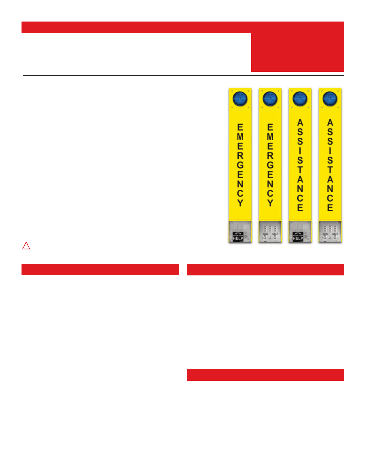
The E-1600-BLTIPEWP, E-1600BLT2IPEWP, E-1600-ASTIPEWP and E-1600AST2IPEWP ADA
Compliant VoIP Emergency Tower Phones are designed to provide quick and reliable handsfree
communication for SIP VoIP phone systems with PoE. The tower phones meet ADA requirements for
emergency telephones, and can be programmed from any touch tone phone or PC on the same LAN
or remotely using a static IP address. The phones can dial up to 5 programmable emergency numbers.
In addition, the E-1600BLT2IPEWP and E-1600AST2IPEWP feature a second "INFO" button that will
dial up to 5 non-emergency numbers.
At the simple push of a button, the Tower Phone will initiate a call to your emergency personnel and
send a digital announcement to identify the location of the emergency call. In addition, the tower phone’s
bright LED strobe light will instantly begin flashing to deter further activity and make it fast and easy for
Police or Security personnel to locate the site of the emergency. The strobe light can also be programmed
to provide a continuous-on lower intensity beacon when the emergency phone is not in use.
All four Tower Phone Models are equipped with Enhanced Weather Protection (EWP) for outdoor
installations where the unit is exposed to precipitation or condensation. EWP products feature foam
rubber gaskets, sealed connections, gel-filled butt connectors, as well as urethane or thermal plastic
potted circuit boards with internally sealed, field-adjustable trim pots and DIP switches for easy on-site
programming. For more information on EWP, see DOD 859.
Installation requires the assistance of a Network Administrator / IT Technician.
!
E-1600-BLTIPEWP E-1600-ASTIPEWPE-1600BLT2IPEWP E-1600AST2IPEWP
Phone Power: PoE class 1 (<4 Watts)
Beacon/Strobe Power: 120VAC / 12VDC power adapter (included)
Maximum Sound Pressure: 90 dB SPL @ 1m
Dimensions: See Installation and Specifications
Operating Temperature: -40°F to 140°F (-40° C to 60° C)
Humidity: Up to 100%
Audio Codecs: G711u, G711a, G722
Network Compliance: IEEE 802.3 af PoE, SIP 2.0 RFC3261,
100BASE-TX with auto cross over
Connections: (1) RJ45 10/100 Base-T, (3) gel-filled butt connectors

2
Viking VoIP SIP System Compatibility List
NOTE: Exclusion from this list means only that compatibility has not been verified, it does not mean incompatibility.
For detailed configuration instructions for certain vendors below, see Configuring Viking VoIP Phone and SIP
Servers, DOD 944.
* Note: Relay operation commands are Not compatible with Panasonic Phone Systems (Panasonic does not transmit DTMF between station ports).
On-Premise
More information
available, see
DOD 944
3COM VCX
3CX
Allwork
4
Aastra
Asterisk
Atcom
Avaya Aura Platform V6.2.9 or earlier
Avaya IP Office Platform
BlueBox
Brekeke
Cisco Unified Communications
Manager (CUCM)
Cisco Unified Communications
Manager Express (CUCME)
Elastix
epygi QX200
4
Freeswitch
Grandstream
4
Interactive Intelligence
iPECS (Ericsson-LG)
4
Iwatsu ECS
4
Kamailio
Mitel 3000
NEC
OfficeSIP
OpenSIPS
Panasonic* (with SIP Extension Card)
PolyCom (SIP paging only)
Samsung Communications Manager
(SCM)
ShoreTel
4
Siemens Communications Server (SCS)
SIP Express Router (SER)
Snom PBX
Sonus
Switchvox
Teksip
Toshiba
Vertical Wave
4
Yealink T Series S IP Phones
Cloud Based Service Provider
More information
available, see
DOD 944
Callcentric
4
iptel.org
MetaSwitch
Ring Central
sip.antisip.com
Switchvox
unify
Vertical Wave
4
Voice Carrier
VoIP.MS
4

3
Definitions
Client: A computer or device that makes use of a server. As an example, the client might request a particular file from the server.
DHCP: Dynamic Host Configuration Protocol. In this procedure the network server or router takes note of a client’s MAC address and
assigns an IP address to allow the client to communicate with other devices on the network.
DNS Server: A DNS (Domain Name System) server translates domain names (ie: www.vikingelectronics.com) into an IP address.
Ethernet: Ethernet is the most commonly used LAN
technology. An Ethernet Local Area Network typically uses twisted pair wires to
achieve transmission speeds up to 1Gbps.
Host: A computer or device connected to a network.
Host Name: A host name is a label assigned to a device connected to a computer network that is used to identify the device in various
forms of network communication.
Hosts File: A file stored in a computer that lists host names and their corresponding IP addresses with the purpose of mapping addresses
to hosts or vice versa.
Internet: A worldwide system of computer networks running on IP
protocol which can be accessed by individual computers or networks.
IP: Internet Protocol is the set of communications conventions that govern the way computers communicate on networks and on the
Internet.
IP Address: This is the address that uniquely identifies a host on a network.
LAN: Local Area Network. A LAN is a network connecting computers and other devices within an office or building.
Lease: The amount of time a DHCP
server reserves an address it has assigned. If the address isn’t used by the host for a period of
time, the lease can expire and the address can be assigned to another host.
MAC Address: MAC stands for Media Access Control. A MAC address, also called a hardware address or physical address, is a unique
address assigned to a device at the factory. It resides in the device’s memory and is used by routers to send network traffic to the correct
IP address. You can find the MAC address of your E-1600-BLTIPEWP/E-1600BLT2IPEWP phone printed on a white label on the top
surface of the PoE LAN port.
Router: A device that forwards data from one network to another. In order to send information to the right location, routers look at IP
Address, MAC Address and Subnet Mask.
RTP: Real-Time Transport Protocol is an Internet protocol standard that specifies a way for programs to manage the real-time transmission
of multimedia data over either unicast or multicast network services.
Server: A computer or device that fulfills requests from a client. This could involve the server sending a particular file requested by the
client.
Session Initiation Protocol (SIP): Is a signaling communications protocol, widely used for controlling multimedia communication sessions
such as voice and video calls over Internet Protocol (IP
) networks. The protocol defines the messages that are sent between endpoints,
which govern establishment, termination and other essential elements of a call.
Static IP Address: A static IP Address has been assigned manually and is permanent until it is manually removed. It is not subject to the
Lease
limitations of a Dynamic IP Address assigned by the DHCP Server. The default static IP Address is: 192.168.154.1
Subnet: A portion of a network that shares a common address component. On TCP/IP networks, subnets are defined as all devices
whose IP addresses have the same prefix. For example, all devices with IP addresses
that start with 100.100.100. would be part of the
same subnet. Dividing a network into subnets is useful for both security and performance reasons. IP networks are divided using a subnet
mask.
TCP/IP: Transmission Control Protocol/Internet Protocol is the suite of communications protocols used to connect hosts on the Internet.
TCP/IP uses several protocols, the two main ones being TCP and IP. TCP/IP is built into the UNIX operating system and is used by the
Internet, making it the de facto standard for transmitting data over networks.
TISP: Telephone Internet Service Provider
WAN: Wide Area Network. A WAN is a network comprising a large geographical area like a state or country. The largest WAN is the
Internet
.
Wireless Access Point (AP): A device that allows wireless devices to connect to a wired network using Wi-Fi, or related standards. The
AP usually connects to a router (via a wired network) as a standalone device, but it can also be an integral component of the router itself.
Wireless Repeater (Wireless Range Extender): takes an existing signal from a wireless router or access point and rebroadcasts it to
create a second network. When two or more hosts have to be connected with one another over the IEEE 802.11 protocol and the distance
is too long for a direct connection to be established, a wireless repeater is used to bridge the gap.
4
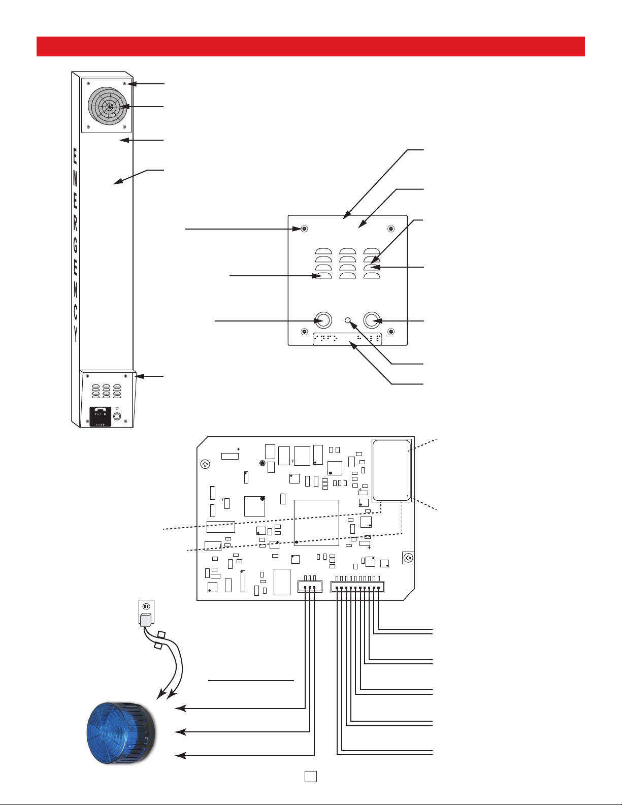
Features Overview
E
M
E
R
G
E
N
C
Y
Mounting Screws: (4) T-10 Torx head stainless steel,
flat head, security screws and drive bit included.
SL-2 Strobe/Beacon: Blue shatter resistant polycarbonate
lens. Designed to meet IP66 ingress Protection Rating.
Tower Chassis: 8 gauge (0.125” thick) aluminum with
weather-resistant high-visibility yellow powder paint.
EMERGENCY lettered in black on
three sides of the tower chassis.
Mounting Screws: (4) T-10 Torx
head stainless steel, flat head,
security screws and drive bit
included.
Microphone: Omni-directional
microphone with protective
water-resistant cloth.
“INFO” Push to Call Button
E-1600BLT2IPEWP
(
316 stainless steel internally
sealed per IP67.
only): Solid
EMERGENCY
PHONE
INFO HELP
CALL
CONNECTED
VIKING
©
Faceplate: Marine grade 316
stainless steel.
Laser Etched Graphics
Speaker: Mylar speaker with
rubber gasket to maintain
water-tight seal and eliminate
water deterioration.
Speaker Screen: Speaker
screen with 0.018" wide slots to
prevent punctures from
paperclips, etc.
“HELP” Push to Call Button:
Solid 316 stainless steel
internally sealed per IP67.
EMERGENCY
PHONE
CALL
CONNECTED
PUSH FOR
HELP
VIKING
©
Green Unit Status LED
Yellow Network Status LED:
Lights steady to indicate power
and data link. Blinks to indicate
network activity.
12V DC Adapter
120V AC
(included)
Rain Guard (included)
-
+
Connect to SL-2
Strobe Light,
included (see pg 6
for proper wiring)
Rear (PCB) View of the Phone Panel
asdesaxtff
2 Amp Relay
Output Contacts
(2A@30VDC/ 250VAC max)
N.C. (Gray)
COM. (Blue)
N.O. (Yellow)
Red Call Connected LED
Grade 2 Braille Label
18E80FXXXXXX
MAC:
- Black
+ Red
Black
Black
White
White
- Black
+ Red
LED
Help Switch
Red
Info Switch (model
E-1600BLT2IPEWP only)
Red
Speaker
Microphone
PoE LAN Port 10/100, PoE
Class 1 (<4 Watts): Connect
to your LAN via RJ45 plug
and CAT5 or greater twisted
pair wire.
MAC Address Label: The
MAC address is aunique 12
digit number used by routers
to send network traffic to the
correct IP address.
5
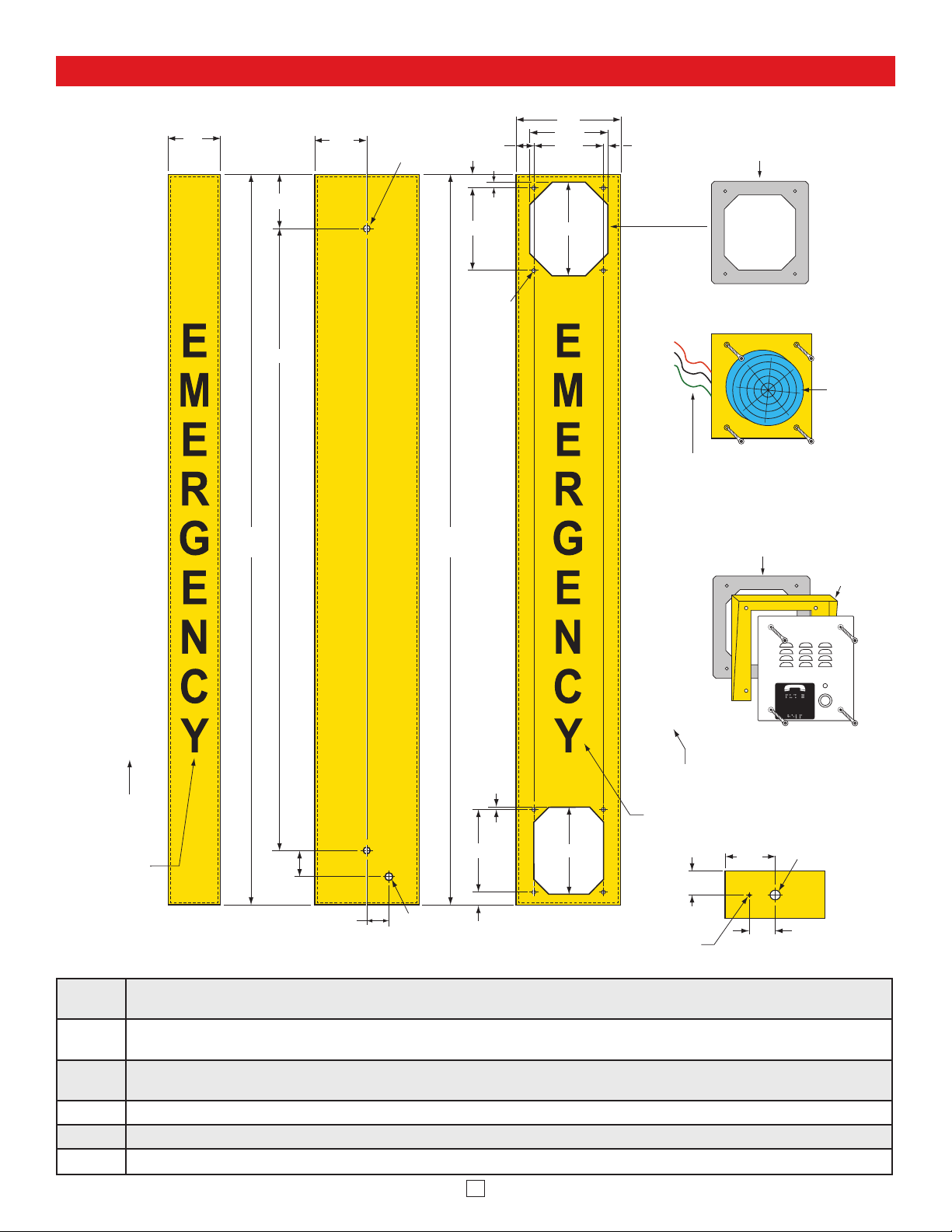
Installation and Specifications
Step 1.
Mount the tower phone approximately 42” above the floor to a flat, sturdy surface using 5/16 hardware. Note: Flat
washers should be used on the main mounting bolts for additional strength.
Step 2.
Locate the strobe light panel and attach red, black and green 42” wire extensions with butt connectors then pass the red,
black and green wires from the strobe panel through the gasket and the upper hole in the tower.
Step 3.
Mount the strobe panel to the tower using the four security screws provided. Attention: To make sure water drain notch
between stobe and panel is facing down, attach strobe panel with wires exiting left side of panel.
Step 4.
Locate the phone panel. Using the gel-filled butt connectors, wire the Strobe Light to the Phone panel as shown on Page 6.
Step 5. Connect CAT 5 or greater Ethernet cable to RJ45. (See Page 8)
Step 6. Mount the phone panel to the tower using the remaining four security screws.
A
S
S
I
S
T
3.0
42.0 in.
(± 0.1)
3.12
35.760
3.00
0.35 Diameter
(2 places)
Use 5/16" bolt
and flat washer
(included)
42.0 in.
Self-clinching
(± 0.1)
1.000
0.75
0.325
4.750
nut 6-32
(8 places)
6.0
4.500
4.000
5.400
0.250
Adhere gasket to chassis,
centering over mounting holes
Strobe Panel
A
S
S
Attention: To make sure water drain
notch between stobe and panel is
facing down, attach strobe panel with
I
wire exiting left side of panel.
S
Adhere gasket to chassis,
centering over mounting holes
T
SL-2
Strobe/
Beacon
Rain Guard
(included)
A
N
C
E
“ASSISTANCE”
on models
E-1600-ASTIPEWP
E-1600AST2IPEWP
or
“EMERGENCY”
on models
E-1600-BLTIPEWP
E-1600BLT2IPEWP
Side View
1.50
1.25
Back View
0.875 Dia.
4.750
0.75
0.125
5.000
Front View
A
N
C
E
“ASSISTANCE” on models
E-1600-ASTIPEWP
E-1600A-AST2IPEWP
“EMERGENCY” on models
0.125 Diameter
Condensation
Drain Hole
or
E-1600-BLTIPEWP
E-1600BLT2IPEWP
1.37
2.87
1.50
CALL
CONNECTED
PUSH FOR
HELP
VIKING©
Phone
Panel
Knockout for
1/2 inch conduit
Bottom
View
6
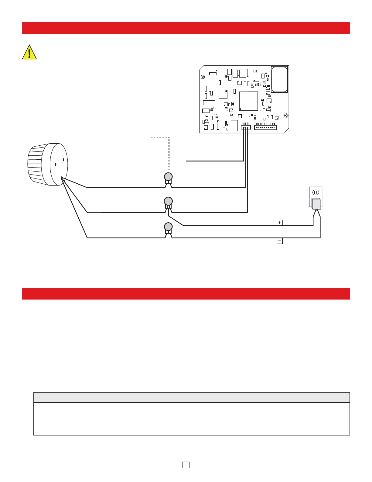
Wiring
IMPORTANT: Electronic devices are susceptible
to lightning and power station electrical surges
from both the AC outlet and the telephone line. It
is recommended that a surge protector be
installed to protect against such surges.
The SL-2 can be user programmed as a Beacon only, Strobe only or Beacon/Strobe. The brightness setting can be
programmed separately for the Strobe or Beacon and one of 4 different Flash Patterns can be programmed for the strobe
(see Strobe Flash Patterns, on page 7). Note: The SL-2 is factory default programmed as a steady on beacon with a
single flash strobe when activated. The beacon and strobe are set to their brightest settings. All programming should be
done prior to connecting to the 2 amp relay contacts on the 1600-IP PCB.
(Optional, the SL-2 is factory programmed to the Beacon/Strobe Mode and brightest Beacon/Strobe settings).
Step 1. Apply 10-15 VDC power to the Red (+) and Black (-) wires.
Step 2.
Touch and hold the Green (Control) wire to the Black (-) wire for 3 seconds. The strobe should flash twice.
You are now in Programming mode. Note: Once in the programming mode, if a programming command
has not been entered for 20 seconds the strobe will flash 3 times indicating the unit has exited programming
and returned to the Run Mode.
Programming the SL-2 Stobe / Beacon
A. Accessing the Programming Mode
Connect to SL-2
Strobe Light
(included)
Gel-Filled Butt
Connectors (included)
Green
(see section A
below)
Red (+)
Black (-)
Rear (PCB) View of the
VoIP Tower Phone Panel
N.C. (Gray)
not connected
COM. (Blue)
N.O. (Yellow)
Important: Polarity Sensitive!
Black with White stripe
Black
18E80FXXXXXX
asdesaxtff
MAC:
(Positive)
(Negative)
120V AC
12V DC
Adapter
(included)
7
Select the Feature: Momentarily touch the Green (Control) wire to the Black (-) wire 1 to
10 times to select which feature to program, see Programming Features List to the right.
The strobe should momentarily flash each time the Green (Control) wire has touched the
Black (-) wire.
Features 1-3 & 6-10: After selecting Programming Features 1-3 or 6-10, wait 3 seconds
and the strobe should flash 2 times indicating that feature has been programmed. You can
now exit programming or move on to programming the Beacon or Strobe brightness settings.
Setting Strobe Brightness (factory set to 6/Brightest): After selecting Programming Feature
4 (Strobe Brightness), wait 3 seconds and the strobe should begin flashing in the
preprogrammed flash pattern. Touch and hold the Green (Control) wire to the Black (-) wire.
The SL-2 will begin flashing the strobe cycling through 6 different brightness settings from
lowest to highest. When the SL-2 flashes at the desired brightness level immediately remove
the Green wire from the Black. The SL-2 should flash twice indicating the selected brightness
level has been set.
Setting Beacon Brightness (Factory set to 6/Brightest): After selecting Programming
Feature 5 (Beacon Brightness), wait 3 seconds and the beacon will light at its
preprogrammed beacon brightness setting. Touch and hold the Green (Control) wire to the
Black (-) wire. The SL-2 will begin stepping through 6 different beacon brightness settings
from lowest to highest. When the SL-2 lights at the desired beacon brightness level
immediately remove the Green wire from the Black. The SL-2 should flash twice indicating
the selected brightness level has been set.
Exiting Programming: To exit programming simply wait 20 seconds from the last
programming command and the unit will flash 3 times. This indicates the SL-2 has exited
the programming mode and is now in the Run mode. Note: To eliminate waiting 20 seconds,
you can also exit programming after the last programming command by touching and holding
the Green (Control) wire to the Black (-) for 3 seconds. The strobe will flash 3 times indicating
the unit has exited the programming mode and is now in the Run mode.
B. Programming Desired Features (after accessing the Programming Mode as shown on page 6)
Feature
Number
Description
1
Beacon/Strobe
(factory default)
2 Strobe Only
3 Beacon Only
4
Strobe Brightness 1-6
(factory default = 6,
brightest setting)
5
Beacon Brightness 1-6
(factory default = 6,
brightest setting)
6
Single Flash Strobe
(factory default)
7 Double Flash Strobe
8 Quad Flash Strobe
9 Flicker Flash Strobe
10
Reset to Factory
Default Settings
Programming Features List
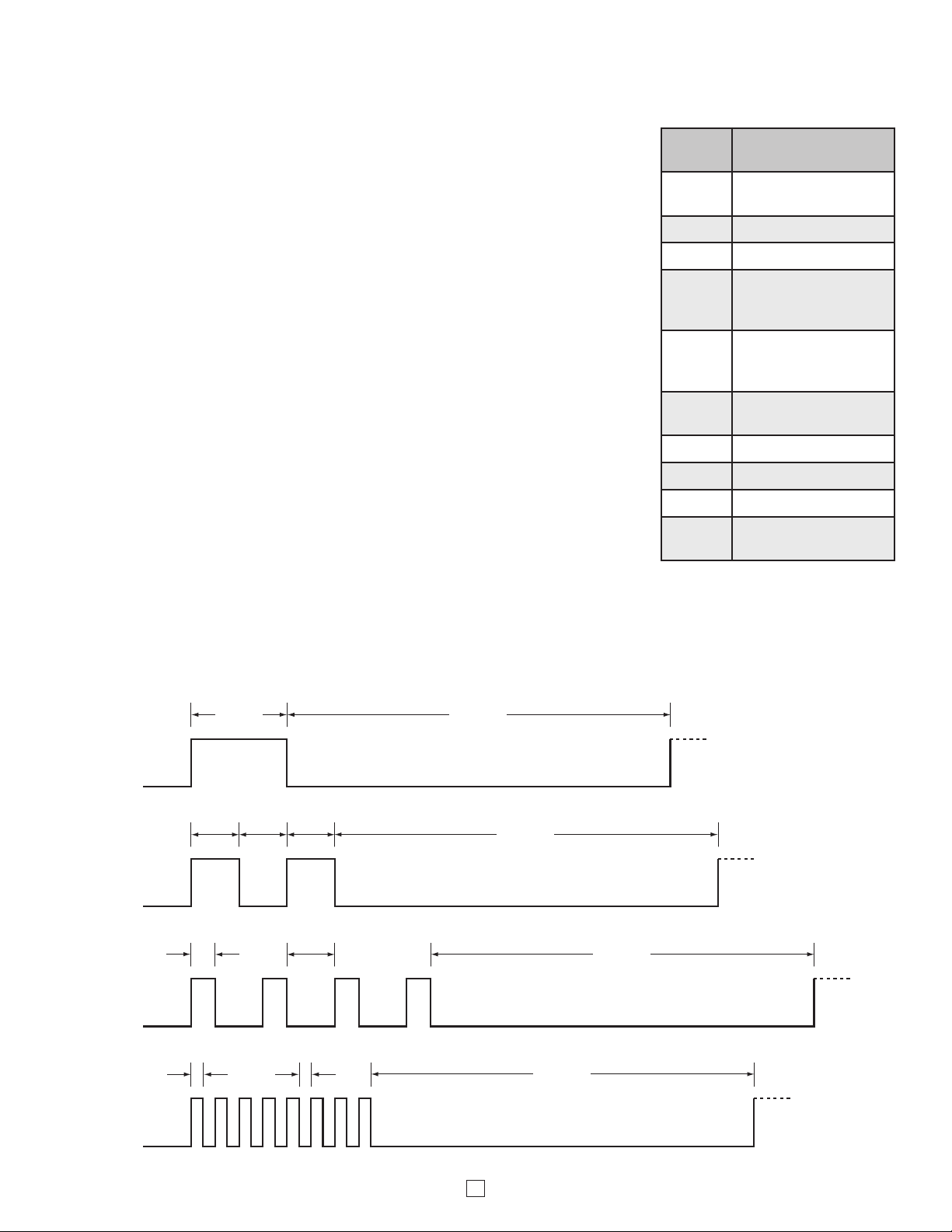
C. Strobe Flash Patterns
0.20 sec
Single
Flash:
Double
Flash:
Quad
Flash:
Flicker
Flash:
0.025
sec
Typ .
ON
0.10
sec
0.10
sec
ON ONOFF
0.05
sec
ON OFF ON ON ONOFF OFF
0.025
sec
Typ .
ON
OFFONOFFONOFFONOFFONOFFONOFFONOFF
0.10
sec
0.10
sec
ON
0.80 sec
Repeat
OFF
0.80 sec
Repeat
OFF
0.80 sec
Repeat
OFF
0.80 sec
Repeat
OFF
8 Pulses
 Loading...