

Page 1
Many new building codes require emergency communication in elevators and
“Area of Refuge” sites. Now you can provide added safety for your patrons,
employees, and students with the addition of High Visibility, ADA Compliant
emergency communication. At the simple push of a button, the E-1600-BLT will
initiate a call to your emergency personnel and send a digital announcement to
identify the location of the emergency call. In addition, the tower phone’s bright
(1million candle power) strobe light will instantly begin flashing to deter further
activity and make it fast and easy for Police or Security personnel to locate the
site of the emergency.
Though the strobe requires external power to operate, rest assured that communication is ALWAYS possible, even during power failures! All phone numbers,
location numbers and programming parameters are stored in non-volatile E
2
memory. No batteries are required to hold the memory.
The E-1600-BLT is equipped for outdoor or harsh environments with Enhanced
Weather Protection (EWP). EWP features rubber gaskets and boots, hand soldered silicon sealed connections, gel filled tip and ring connectors, as well as urethane potted circuit boards with internally sealed, field-adjustable trim pots and
DIP switches for
easy on-site programming.
PPhhoonnee......771155..338866..8888661
1
PPrraaccttiicce
e
T
T
EELLEECCOOM
M
S
S
OOLLUUTTIIOONNSSFFOORRTTHHE
E
221
1
SST
T
C
C
EENNTTUURRY
Y
Phone Power: Telephone line powered (24V DC/20mA min)
Strobe Power: 120V AC/12V DC power adapter (included)
Maximum Strobe Power Run: 200 feet using 24 awg wire
Dimensions: 1070mm x 152.4mm x 109.3mm (42” x 6” x 4.5”)
Shipping Weight: 5.9 kg (13 lbs)
Connections: 10 pin screw terminal block
Mounting: Surface mount to rigid wall or post
Environmental: -26ºC to 54ºC (-15ºF to 130ºF) with 5% to 95%
non-condensing humidity
Strobe Output: 1,000,000 candle power
Material: Enclosure - .125 aluminum, 76.2mm x 152.4mm (3” x
6”) tube, powder painted high-visible yellow, Phone - .074 (14 ga)
stainless steel with stainless steel button, Strobe - Vandal resistant polycarbonate plastic
• Enhanced Weather
Protection (EWP)
• Non-volatile digital voice announcer with 10 seconds
of voice memory
• Handsfree operation
• Telephone line powered-communication during power
failure
• Non volatile E
2
memory
• 1 million candle power blue strobe light
• Touch Tone or pulse dialing
• Dials up to 5 different numbers on busy or no answer
• Transmits a unique location I.D. code
• “Call Connected” LED for the hearing impaired
• Grade 2 Braille label for the visually impaired
• Disconnects on CPC, silence, busy signal, dial tone,
time-out or Touch Tone command
• Automatically answers incoming calls
• Remotely programmable
• “Central Station Monitoring” compatible
• High visibility, vandal and weather resistant
• Vandal resistant polycarbonate strobe lens
• Surface mountable
FFeeaattuurrees
s
• Campus Security Sites
• Area of Refuge sites
• Parking Ramps/Lots
• Automated Tellers (ATM)
• Entryways
• Roadside Emergency Sites
• Stairwells in Public Buildings
TECHNICAL
TECHNICAL
AApppplliiccaattiioonns
s
SSppeecciiffiiccaattiioonns
s
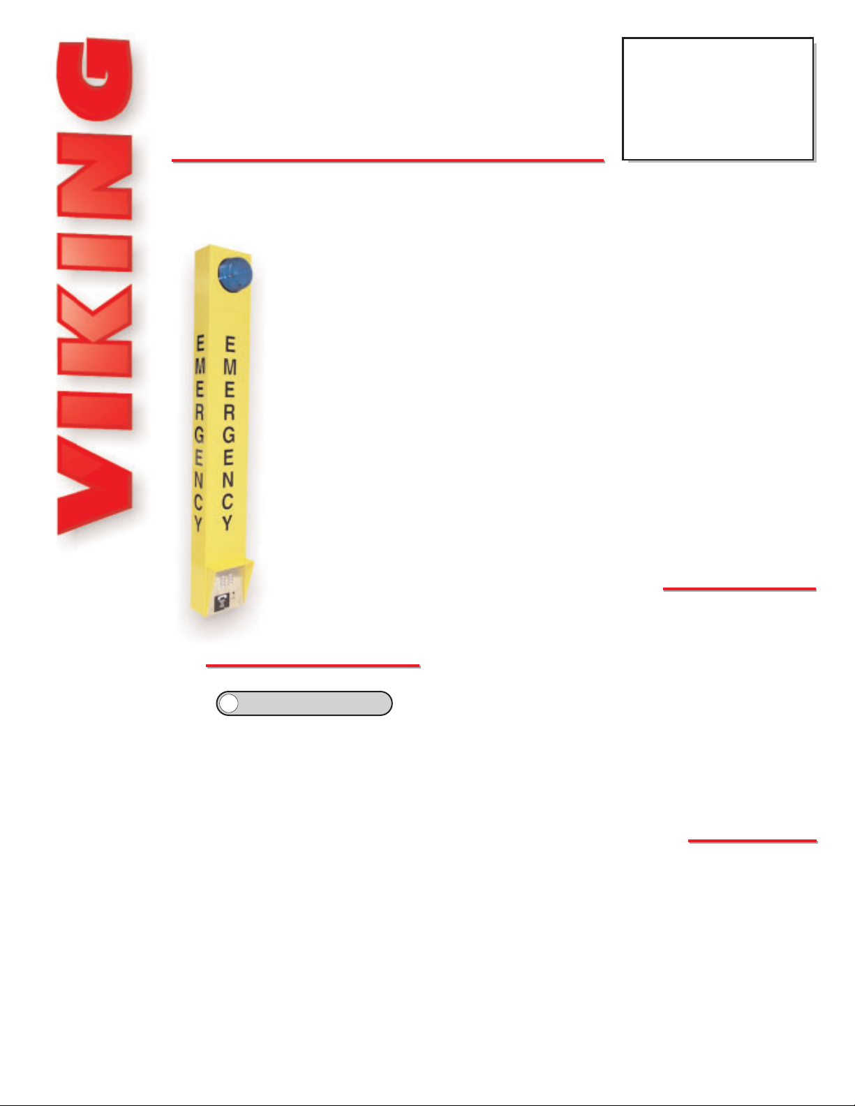
ADA Compliant Emergency Tower Phone with
Blue Strobe Light and Voice Announcer
E-1600-BL
E-1600-BLTT
ADA Compliant
Emergency Tower
Phone with Strobe
December 26, 2001
hhttttpp::////wwwwww..vviikkiinnggeelleeccttrroonniiccss..ccoom
m
?
?
Need More Information on EWP?
Call (715) 386-4345 and select 859.
Page 2
IInnssttaallllaattiioon
n
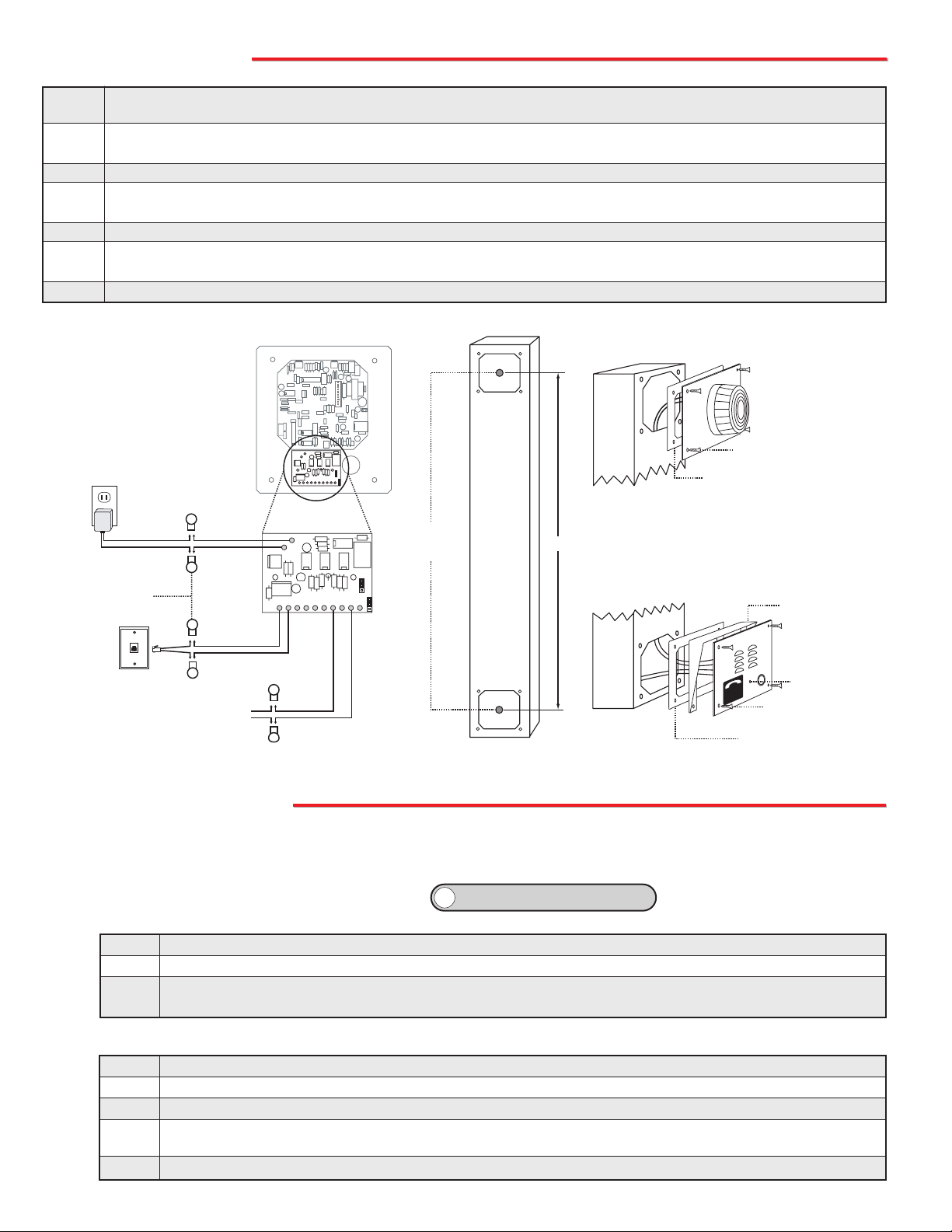
Step 1. Mount the tower phone approximately 42” above the floor to a flat, sturdy surface using 5/16 hardware. Note: Flat
washers should be used on the main mounting bolts for additional strength.
Step 2. Locate the strobe light panel and pass the red and black wires from the strobe panel through the gasket and the upper
hole in the tower.
Step 3. Mount the strobe panel to the tower using the four security screws provided.
Step 4. Locate the phone panel. Using the moisture-proof connectors, connect the red and black wires labelled “Strobe Light” to
the red and black wires on the strobe panel.
Step 5. Connect the phone line to the red and green wires (this connection is not polarity sensitive).
Step 6. Connect the 12V DC adapter wires black (+) and black with white stripe (-) to the black and black with white stripe wires
from the LDB-2 Strobe Control Board.
Step 7. Mount the phone panel to the tower using the remaining four security screws.
The E-1600-BLT emergency phone can be programmed from any Touch Tone phone using a C.O. line, analog
PABX/KSU station, or a DLE-200B Line Simulator.
A. Accessing the Programming Mode
PPrrooggrraammmmiinng
g
Step 1. Move DIP switch 2 to the ON position (sets unit to answer incoming calls, see section K).
Step 2. From a Touch Tone phone call the line attached to the E-1600-BLT phone.
Step 3. When the E-1600-BLT phone answers, enter the 6-digit security code (factory set to 845464, see section C). A
double beep should then be heard indicating you have entered the programming mode.
2. Without the Security Code
1. Using the Security Code
Step 1. Move DIP switch 2 to the ON position (sets unit to answer incoming calls, see section K).
Step 2. Move DIP switch 3 to the OFF position (incoming calls enter Programming without security code, see section K).
Step 3. From a Touch Tone phone call the line attached to the E-1600-BLT phone.
Step 4. When the E-1600-BLT answers, a double beep will be heard and you will automatically enter the programming
mode.
Step 5. When finished programming, move DIP switch 3 back to the ON position (see section K).
?
?
Need More Information on the DLE-200B?
Call (715) 386-4345 and select 605.
120V AC
12V DC
Adapter
(included)
(6) Moisture-proof
Butt Connectors
(included)
Phone
Line
Black with
White Stripe (-)
Black (+)
Black with
White Stripe
Black
Green (ring)
Red (tip)
To Strobe
Light
(included)
Rear View of Phone
LDB-2 Strobe
Control Board (included)
1 2 3 4 5 6 7 8 9 10
Black (-)
Red (+)
Use 5/16" bolt
and flat washer
(included)
E
M
E
R
G
E
N
C
Y
35.76"
Strobe Panel
(4) Stainless steel spanner
head screws (included)
Adhere gasket to front panel,
centering over mounting holes
Phone Panel
LL
CA
T
C
SH
ONNE
U
C
P
O
T
L
L
A
C
Adhere gasket to chassis,
centering over mounting holes
Rain Guard (included)
"Call Connected LED
D
E
(4) Stainless steel spanner
head screws (included)
Page 3
C. Security Code (memory location #19)
The security code allows the user/installer to program the E-1600-BLT phone while DIP switch 3 is in the ON (normal)
position. The factory set security code is 845464 (V-I-K-I-N-G). It is recommended that the factory set security code
be changed. Example: To store 123456 as the security code:
D. Emergency Speed Dial Numbers (memory locations #00 - #04)
The emergency speed dial number programmed in location #00 is the telephone or
extension number that is dialed when the “Push To Call” button is first pressed.
Additional speed dial numbers will be dialed when there is no answer or a busy signal is detected and the next number redial features are activated. The E-1600-BLT
phone will cycle through the programmed speed dial numbers until answered. To
program, enter the desired speed dial number followed by the location number (#00
- #04).
To clear a speed dial location, simply enter the memory location (#00 - #04) alone.
The E-1600-BLT phone is factory set with no speed dial number programmed.
F. Identification Number (memory location #20)
The Touch Tone I.D. number (up to 20 digits) is used by emergency personnel to identify the location of the caller and
is given out when the receiving party presses a Touch Tone
,. The security office can display the number using a Touch
Tone decoder. To program the I.D. number, enter the desired number followed by #20.
Example: To store 333 as the I.D. number, enter: 3 3 3 # 2 0
B. Quick Programming Features
First emergency speed dial number .........................................................................
Second emergency speed dial number ...................................................................
Third emergency speed dial number .......................................................................
Fourth emergency speed dial number .....................................................................
Fifth emergency speed dial number .........................................................................
Central station receiver number ...............................................................................
Central station voice number ...................................................................................
Voice announcer options (factory set to 000000) .....................................................
Timing/Dialing options (factory set to 234111) .........................................................
Security code (factory set to 845464) ......................................................................
Identification number (factory cleared) ....................................................................
Note: A double beep indicates a valid memory position, four beeps indicate an error.
0-20 digits
0-20 digits
0-20 digits
0-20 digits
0-20 digits
0-20 digits
0-20 digits
6 digits
6 digits
6 digits
0-20 digits
#00
#01
#02
#03
#04
#05
#06
#17
#18
#19
#20
Enter Digits
Note: Up to 20 digits can be stored in each dial position. Special features such as pause, mode change, Touch Tone
,
and # count as single digits.
To Program:
,
#
4 second pause
switch to pulse mode
0, 1, 2...9
Enter:
,,
,#
,7
,6
0, 1, 2...9
Enter Your Security Code Here:
#19
then
then
then
then
then
then
then
then
then
then
then
- then -
Enter Memory Location
Step 1. Access programming as shown in Programming section A.
Step 2. Enter 123456 #19..
Step 3. Hang-up.
Note: The security code must be 6 digits and cannot include a ,or a #.
E. Programming Examples
To Program the E-1600-BLT Phone...
...to store 555-1234 as the first emergency speed dial number
...to store a Touch Tone 9, a four second pause and then a pulse
dialed 333-4444 into the second speed dial memory position
...to clear the first emergency speed dial number
Step 2 - Enter Digits:
5 5 5 1 2 3 4 # 0 0
9
,7 ,6 3 3 3 4 4 4 4 # 0 1
# 0 0
Step 1 -
See Section A
Enter Programming
Enter Programming
Enter Programming
Page 4

If enabled and a busy is detected, the E-1600-BLT phone will dial the next pro-
grammed speed dial number, and continue to cycle through the emergency numbers until a call is completed.
* Notes: This feature is disabled in the factory default setting. If the busy signal is
interrupted with a promotional message, contact your central office to have it
removed.
Setting E - Dial Next Number on Busy
Setting F - Pulse Dialing Rate (Pulses per second)
The E-1600-BLT phone is capable of different pulse dialing speeds.
* Note: The factory default setting is 10pps.
Setting C - Silence Time Out
This feature selects the length of time that calls will remain connected without voice activity. Programmable in increments of 10 seconds up to a maximum of 90 seconds (Touch
Tones 1 - 9). To disable the silence time out, program 0 in this location. Use chart at the
far right.
* Note: The factory default is 40 seconds.
Setting D - Dial Next Number on Ring No Answer
If enabled and a ring-no-answer is detected, the E-1600-BLT
phone will dial the next programmed speed dial number, and continue to cycle through the emergency numbers until a call is completed.
* Note: This feature is disabled in the factory default setting.
Touch Tone
1 or 0
2, 3, 4...9
Setting D
Disabled*
Dials second number after
2, 3, 4...9 rings respectively
Setting A - Talk/Listen Delay
This feature selects switching time between talk and listen modes (VOX switching time).
Use chart at the far right.
* Note: The factory default is .2 seconds.
Setting B - Call Length Time Out
This feature selects the maximum length of time that calls can be
connected. Programmable in increments of 1 minute up to a maximum of 9 minutes (Touch Tones 1 - 9). Program 0 in this location to
disable the call length time out. With the call length disabled, the E-
1600-BLT phone must rely on a CPC signal, busy signal, silence or
return to dial tone to hang-up. Use chart at the right.
* Note: The factory default is 3 minutes.
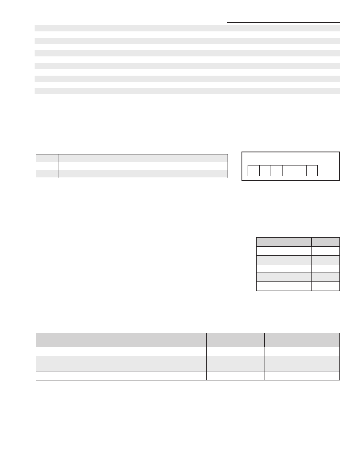
G. Timing/Dialing Options (memory location #18)
There are six positions in the timing/dialing options. To program these options, enter the six desired timing/dialing numbers followed by #18. The six available timing/dialing options are defined as follows:.
Dial:A+B+C+D+E+F+#+1+8
Factory Default Setting: 2 + 3 + 4 + 1 + 1 + 1
Talk/Listen Delay
Call Length
Silence Time Out
Dial Next Number on Ring No Answer
Dial Next Number on Busy
Pulse Dial Speed
Enter Timing/Dialing Settings Here:
A B C D E F
#18
Touch Tone
1
2
Setting F
10 pps*
20 pps
Touch Tone
1
2
Setting E
Disabled*
Enabled
Touch
Tone
1
2
3
4
5
6
7
8
9
Talk/Listen
Delay
.1 sec
.2 sec *
.3 sec
.4 sec
.5 sec
.6 sec
.7 sec
.8 sec
.9 sec
Touch
Tone
0
1
2
3
4
5
6
7
8
9
Call Length
Time Out
Disabled
1 min
2 min
3 min*
4 min
5 min
6 min
7 min
8 min
9 min
Touch
Tone
0
1
2
3
4
5
6
7
8
9
Silence
Time Out
Disabled
10 sec
20 sec
30 sec
40 sec*
50 sec
60 sec
70 sec
80 sec
90 sec
Page 5

The E-1600-BLT can be programmed to play the announcement from 1-9
times, or to continuously repeat the announcement every 8 seconds until
a Touch Tone
, is detected from the distant party. The I.D. number (if pro-
grammed) will be sent and the call connected LED will turn on automatically after the announcement has stopped repeating.
* Note: The factory default for the E-1600-BLT phone is to repeat until a
,
is detected (digit 0).
The E-1600-BLT phone is factory set to automatically start playing the voice
announcement after it has determined the call has been answered.
Alternately, the announcement may be programmed to play after a programmed amount of time, from 1 to 99 seconds after dialing.
* Note: If the announcement delay time is used, it is important to allow enough time for the E-1600-BLT phone to
detect ring-no-answer and busy signals when using the redial features. The factory default is set to play automatically.
I. Recording the Announcement
J. Automating the Call Connected LED
There are two methods of turning on the Call Connected LED. The LED will turn on after a Touch Tone , is detected
from the distant party or after the voice announcer is finished playing a programmed number of times. If you want the
Call Connected LED to light automatically when the call has been answered, but you don’t want a voice announcement
to be played, follow these programming steps:
Settings A and B - Announcement Delay
H. Voice Announcer Options (memory location #17)
The E-1600-BLT phone have a built-in non-volatile digital voice announcer that may be used to identify the location of
the emergency phone call. The 10 seconds of digital record time is recorded remotely from a Touch Tone phone.
Programming options are as follows:
Dial:A+B+C+D+E+F+#+1+7
Factory Default Setting: 0 + 0 + 0 + 0 + 0 + 0
Two Digit Announcement Delay {
Repeat Announcement Setting
Future Use (enter “0”)
Enter Settings Here:
A B C D E F
0 0 0 #17
Touch Tone
00
01-99
Setting A/B
Play automatically
1-99 seconds*
Touch Tone
0
1-9
Setting C
Repeat every 8 secs*
Repeat 1-9 times
Step 1:
Access Programming as shown in section A
Step 3:
Enter digits: 001000#17
Step 2:
Make a short (1 second) recording of silence
Setting C - Repeat Announcement Option
Step 1. Call into the E-1600-BLT phone with a Touch Tone phone and access programming.
Step 2. Enter
,4, wait for the tone and then begin recording. Ten seconds of record time is available.
Step 3. Enter any Touch Tone to stop the recording. Playback is automatic.
Step 4. Enter
,5 to review the announcement again.
Step 5. If you choose to not use a voice announcement, enter ,3 to clear the recording.
Example: “Elevator number 1215, located in the Financial Building, needs assistance. Press the asterisk (,) key on
your telephone to start and stop this announcement...”
Page 6

The E-1600-BLT phone can be programmed to dial a central station receiver only, or dial up to 5 voice numbers
first, and if no answer, then dial the central station receiver. When calling the first numbers (memory positions
#00-#04 (see Programming section D), the phone stays in “two-way talk mode” allowing two-way conversation.
When calling the Central Station number (memory position #05), the phone is in a “listen only mode” in order to
interpret the hand shake signals of the receiver.
A second central station number position has been provided in location #06 that is used when the central station receiver does not have a talk over mode. If a number is placed in position #05 and position #06 is cleared,
the E-1600-BLT will call the central station monitor receiver. After the receiver sends a kiss-off, the E-1600-BLT
lights the “Call Connected” LED and goes into two-way talk mode.
If numbers are in both positions #05 and #06, the E-1600-BLT will
call the receiver first, and after the kiss-off, will hang-up and redial
the number in position #06 for two-way voice communication
Notes: If only a central station is to be dialed, the central station
phone number must be preprogrammed in memory location #05
and memory locations #00-#04 must be cleared. The “Call
Connected” LED will light automatically if there is a voice recording
programmed.
b. Enabling/Disabling Central Station Mode
The E-1600-BLT emergency phone can be placed in the “Central Station Mode” by entering a central station
phone number in position #05 while programming. To cancel the “Central Station Mode,” clear position #05 by
entering #05 only (see Programming section D).
c. Ring Delay
When the E-1600-BLT emergency phone is in the “Central Station Mode”, it should have the ring delay set to
a minimum of three, because some receivers send a long tone after answering the line that sounds like a ring
back. If the E-1600-BLT is set to a ring delay of two, the phone will disconnect (see Programming section G).
d. Speed Dial Numbers
The standard E-1600-BLT emergency phone is capable of communicating using the “Ademco Contact I.D.”, “Ademco
High Speed”, “DTMF 4+1 Express”, or the “DTMF 4+2 Express” formats. All formats use the programming memory
location #20 to store the account code and alarm details.
a. Accessing the Programming Mode
Before programming, you must access the programming mode (see Programming section A).
1. Central Station Programming Features
L. Central Station Programming
To Program the E-1600-BLT Phone...
...to enable central station programming and dial 952-2567
...to disable central station programming
Step 2 - Enter Digits:
9 5 2 2 5 6 7 # 0 5
# 0 5
Step 1:
Enter Programming
Enter Programming
Location
#00
#01
#02
#03
#04
#05
#06
Call Type
Voice - Emergency
Voice - Emergency
Voice - Emergency
Voice - Emergency
Voice - Emergency
Central Station Receiver
Central Station Voice Line
K. DIP Switch Programming/Speaker and Microphone Adjustments
Two POTs are provided to increase or decrease speaker volume and microphone sensitivity. In certain noisy locations
the microphone sensitivity may need to be decreased as shown below. Caution: Setting the microphone gain too high
may cause distorted audio, prevent the distant party from breaking over and inhibit second number redialing.
DIP
Switch
1
1
2
2
3
3
Position
ON
OFF
ON
OFF
ON
OFF
Description
“Push to Call” button alternately connects
and disconnects calls (factory default)
“Push to Call” button connects calls only
Incoming calls answered (factory setting)
Incoming calls are not answered
Normal operation mode (factory setting)
Learn mode - Any incoming calls are automatically entered into the programming
mode (no security code required). Use this
option if you have forgotten your security
code.
Speaker
Volume
Microphone
Sensitivity
DIP Switches
1
2
3
Off On
(DIP Switches shown
in factory setting)
Page 7

A. Standard Operation
OOppeerraattiioon
n
b. Ademco High Speed Format
This DTMF format consists of a four digit account code, eight zone codes and one alarm type digit. With this
format you can identify up to eight different
phones by using a zone per phone. A “5” in a
zone position means no alarm. The following
example shows an alarm from the third phone.
2. Central Station Formats
The following examples explain the receiver formats and how to properly program memory location #20. Each format starts with a four digit account code. This is the code that is assigned by your central station for billing purposes. You must access the programming mode before programming these features (see Programming section A).
Important: If a number is shown, you must use that number. If an “X” is shown, use any appropriate number.
c. 4+1 Express Format
This DTMF format consists of a four digit account code,
two digit message type, and a single digit event code.
Account Code
Message Type
XXXX 17 X #20
Account Code
Idle Zone
XXXX 55 1 55555 7 #20
a. Ademco Contact ID Format
This DTMF format consists
of a four digit account code,
two digit message type, and
a nine digit data
field.
Account Code
Message Type
New Event
XXXX 18 1 14000 XXX #20
Memory Location
Any number to identify phone
General Alarm
d. 4+2 Express Format
This DTMF format consists of a four digit account
code, two digit message type, and a two digit event
code.
Account Code
Message Type
XXXX 27 XX #20
Memory Location
Normal Alarm
New Event
Memory Location
Event Code
Memory Location
Event Code
Enter Contact ID Settings Here: 18 1 14000 #20
Enter Ademco High Speed ID Settings Here: 55 1 55555 7 #20
Enter 4+1 Express ID Settings Here: 17 #20
Enter 4+2 Express ID Settings Here: 27 #20
When the Push to Call button is pressed, the E-1600-BLT phone goes off-hook and dials a pre-programmed telephone
number. The Call Connected LED momentarily flashes during tone or pulse dialing. While the emergency call is in
progress, the blue strobe will flash. In the event that the line is busy or there is a ring-no-answer, the unit can be programmed to call additional phone numbers. The emergency phone then cycles through up to 5 pre-programmed numbers until the call is answered. When the call is answered, handsfree communication to emergency personnel is established. The digital voice announcer will automatically play to identify the location of the emergency call. The
, key will
stop the announcement, send the Touch Tone I.D. number (if programmed) and light the “Call Connected” LED.
Alternatively, the E-1600-BLT phone can be programmed to automatically light the “Call Connected” LED after the
announcement has played a programmed number of times. The distant party will know the location of the emergency
call by either the voice announcement or by decoding the Touch Tone I.D. number. Pressing the , key again will send
the I.D. number and play the message again. Once the , key has been pressed, the # key can be used to force the
E-1600-BLT phone to hang-up.
Page 8

Due to the dynamic nature of the product design, the information contained in this document is subject to change without notice. Viking Electronics, and its affiliates and/or
subsidiaries assume no responsibility for errors and omissions contained in this information. Revisions of this document or new editions of it may be issued to incorporate
such changes.
Fax Back Doc 217
ZF301250 Rev B
Printed in the U.S.A.
PPrroodduuccttSSuuppppoorrttLLiinnee......771155..338866..8866666
6
FFaaxxBBaacckkLLiinnee......771155..338866..4433445
5
B. Central Station Operation
After the button on the E-1600-BLT phone has been pressed the E-1600-BLT phone will begin to dial. If a voice num-
ber is programmed in memory locations #00-#04, these numbers will be dialed first. Upon detecting a busy signal or
after a preprogrammed ring delay the E-1600-BLT phone will hang-up and dial the central station phone number stored
in memory location #05. When the central station receiver answers, it will send a handshake tone to the E-1600-BLT
phone. Upon detecting the handshake tone, the E-1600-BLT phone will begin downloading the information stored in
memory location #20.
Once the E-1600-BLT emergency phone has sent the information stored in memory location #20, it waits for a “kiss-
off” tone from the central station. When the “kiss-off” tone is received, the emergency phone turns on the call connected LED and goes into the “two-way talk mode” or hangs up and dials position #06 if programmed. Note: The central
station should have a “talk-over” feature that will allow a two way conversation at this time. If your receiver does not
support a “talk-over”. A voice phone number should be programmed into position #06.
If the central station answers the call and does not send a “kiss-off”, the next number will be dialed (if programmed). In
either single number or multi-number programming, the phone will keep dialing until a call is completed.
OOppttiioonns
s
PB-100 Polling and Diagnostics Kit
The PB-100 system provides centralized polling and diagnostics of all Viking 1600 and
1600A series emergency phones through a standard Windows 9x/NT P.C. In addition, any
device or human capable of returning DTMF Touch Tones can be automatically polled.
Up to 500 individual phones can be polled, at timed intervals, for the diagnosis of proper programming and operation. The included software provides storage of complete contact/location records associated with the
phones ID.
Devices that are polled successfully are stored in a "success" log while
devices that returned any kind of error are stored in a "failure" log.
PB-100
System
?
?
Need More Information on the PB-100?
Call (715) 386-4345 and select 860.
programming parameters, including phone numbers and location numbers, are stored in non-volatile E2memory. All units
are phone line powered, requiring no batteries or external power and are compatible with common Central Station
Monitoring equipment.
For outdoor or harsh environments, select 1600A Series phones are available with Enhanced Weather Protection (EWP).
EWP products feature rubber gaskets and boots, hand soldered silicon sealed connections, gel filled tip and ring connectors, as well as urethane potted circuit boards with weather sealed, field-adjustable trim pots and DIP switches for easy onsite programming.
The 1600A Series ADA Compliant Emergency Phones are designed
to provide quick and reliable handsfree communication over the public switched telephone network. All 1600A Series phones meet ADA
requirements for elevator/emergency telephones, and can be pro-
grammed from any Touch Tone phone. The phones can dial up
to 5 programmable emergency numbers, as well as 2 central
station numbers. In addition, the E-1600-20A features an
"Info" button that will dial up to 3 non-emergency
numbers.
The 1600A Series phones can be programmed to
automatically deliver a digital announcement to identify the location of the emergency call and then initiate the call connected LED light. Alternatively, a
DTMF Touch Tone code may also be delivered. All
E-1600-45A
K-1600-EHFA
E-1600A
E-1600-02A
E-1600-03A
E-1600-20A
1600A Series ADA* Compliant Emergency Phones with Built-In Digital Voice Announcer
?
?
Need More Information on the 1600A Series?
Call (715) 386-4345 and select 215.
 Loading...