

Viking E-1600A, E-1600A series, E-1600-45A, E-1600-60A, E-1600-65A Product Manual
Designed, Manufactured and Supported in the USA
VIKING
COMMUNICATION & SECURITY SOLUTIONS
PRODUCT MANUAL
E-1600A-MK-GNP
E-1600A Gooseneck
Pedestal Mounting Kit
December 20, 2016
Gooseneck Pedestal Mounting Kit for the
E-1600A, E-1600-45A, E-1600-60A and E-1600-65A
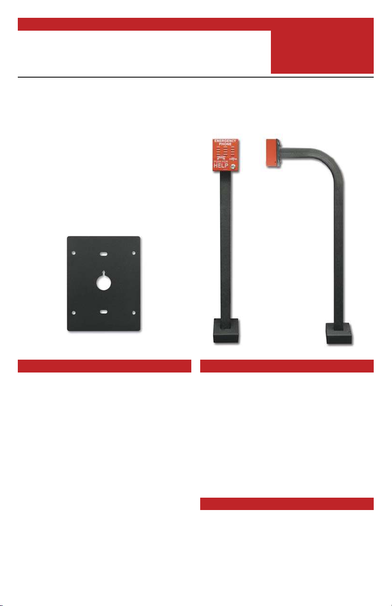
The model E-1600A-MK-GNP is a mounting kit
for attaching the E-1600A, E-1600-45A, E-
1600-60A or E-1600-65A Emergency Phone to
a Viking VE-GNP gooseneck pedestal.
The kit includes stainless steel mounting hardware, two gaskets to seal the back of the Emergency Phone and a durable powder coated 12
gauge steel mounting plate.
E-1600A-MK-GNP Mounting Plate
Features
• E-1600A-MK-GNP allows the E-1600A,
E-1600-45A, E-1600-60A or E-1600-65A
Emergency Phone to be mounted directly
to a Viking VE-GNP gooseneck pedestal
• Durable 12 gauge steel mounting plate
• Plate is powder coat primed then top
coated with a UV stable black textured
powder coat
• Stainless steel mounting hardware is included
• Two gaskets are included for sealing the
back of the Emergency Phone to the
gooseneck pedestal
www.vikingelectronics.com
Information: (715) 386-8861
Model E-1600A
Emergency Phone
shown with VE-GNP
Pedestal and
E-1600A-MK-GNP
Mounting Kit
Applications
• For mounting the following Viking Emergency Phones to a Viking VE-GNP
gooseneck pedestal for emergency pool
phone applications etc.
- E-1600A Red Emergency Phone
- E-1600-45A Yellow Emergency Phone
- E-1600-60A “Police” Emergency Phone
- E-1600-65A Blue Emergency Phone
For more information on Viking Emergency Phones, see DOD# 215
Specifications
Dimensions: 5.37” x 3.40” x 0.105” (136.4mm x
86.4mm x 2.67mm)
Shipping Weight: 1.2 lbs (0.544 kg)
Environmental: -40°F to 150°F (-40°C to 65°C)
with up to 100% humidity
Included Hardware: (4) #10-24 x 5/8 stainless
steel truss head screws, (4) 10-24 stainless steel
nylock nuts
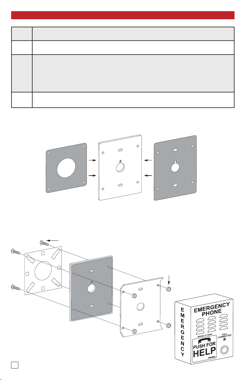
Installation
Step 1.
Step 2.
Step 3.
Step 4.
Adhere the square gasket to the E-1600A-MK-GNP mounting plate. Make sure gasket is
centered and holes align. (Figure 1)
Adhere the rectangular gasket to the other side of the E-1600A-MK-GNP mounting plate.
Make sure gasket is centered and holes and arrow symbol align. (Figure 1)
Place the E-1600A back plate on the rectangular gasket side of the E-1600A-MK-GNP
mounting plate. Pull the wires through the center hole on the plates. Make sure the arrow
symbol on the E-1600A-MK-GNP mounting plate is pointing UP then attach the
square gasket side of the plate to the VE-GNP pedestal mounting plate with the 4 truss
head screws and nylock nuts as shown. Do not tighten screws until all 4 screws are inserted and plate is aligned. (Figure 2)
Attach the wires from the pedestal to the E-1600A with provided butt connectors then fasten the E-1600A to mounting plate by tightening the set screw on the bottom of the unit.
Figure 1
Square Gasket
(included)
E-1600A-MK-GNP
Mounting Plate
(included)
Rectangle Gasket
(included)
mounting plate
(not included)
see DOD# 424
2
VE-GNP
(4) #10-24 x 5/8 Truss Head screws
included with mounting kit
E-1600A-MK-GNP Mounting Plate
with both gaskets adhered
Figure 2
E-1600A back plate,
included with model E-1600A
(4) 10-24 Nylock nuts
included with mounting kit
Model E-1600A
(not included) see DOD# 215
 Loading...