

PRODUCT MANUAL
Designed, Manufactured and Supported in the USA
COMMUNICATION & SECURITY SOLUTIONS
Tower Phones
ADA Compliant
Emergency Tower Phones
February 26, 2019
VIKING
Features
Applications
Specifications
• Campus Auditoriums
• Parking Ramps/Lots
• Automated Tellers (ATM)
Viking Tower Phones provide added safety for your patrons, employees, and students with the
addition of high visibility, ADA compliant communication. At the simple push of a button, the
E-1600A-AST-EWP or E-1600A-BLT-EWP will initiate a call to your personnel and send a
digital announcement to identify the location of the call. In addition, the tower phone’s bright
LED strobe light will instantly begin flashing to deter further activity and make it fast and easy
for Police or Security personnel to locate the site of the call. The strobe light can also be
programmed to provide a continuous-on lower intensity beacon when the phone is not in use.
Though the strobe requires external power to operate, rest assured that communication is
possible, even during power failures! All phone numbers, location numbers and programming
parameters are stored in non-volatile memory. No batteries are required to hold the memory.
These tower phones are equipped with Enhanced Weather Protection (EWP) for outdoor
installations where the unit is exposed to precipitation or condensation. EWP products feature
foam rubber gaskets, sealed connections, gel-filled butt connectors, as well as urethane or
thermal plastic potted circuit boards with internally sealed, field-adjustable trim pots and DIP
switches for easy on-site programming. For more information on EWP, see DOD 859.
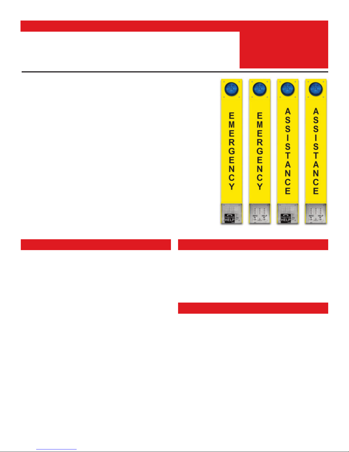
ADA Compliant Tower Phones with Blue
Steady On LED Beacon and Strobe Light
E-1600A-AST-EWP E-1600A-AS T2EWP
• Entryways
• Stairwells in Public Buildings
Phone Power: Telephone line powered. Minimum 24V DC talk battery voltage,
with a minimum loop current of 20mA. Loop current may be boosted on low
current lines with a Viking Model TBB-1B talk battery booster (DOD 632).
Beacon/Strobe Power: 120V AC / 12V DC power adapter (included)
Maximum Strobe Power Run: 200 feet using 24 AWG wire
Dimensions: 42” x 6” x 4.5” (1070mm x 152.4mm x 109.3mm)
Shipping Weight: 20 lbs (9.1 kg)
Mounting: Surface mount to rigid wall or post
Operating Temperature: -15°F to 130°F (-26°C to 54°C)
Humidity: Up to 100%
Strobe Flash Rate: 60 flashes per minute (default), see page 7 for more info
Maximum Strobe Light Output @ 15VDC: Clear lens: 323 lumens, Amber
lens: 242 lumens, Blue lens: 116 lumens, Red lens: 66 lumens
Maximum Power Supply Run Length on CAT-5: 1 pair = 125 ft, 2 pair =
225 ft, 3 pair = 325 ft, 4 pair = 475 ft
Enclosure Material: 0.125” aluminum, 3” x 6” (76.2mm x 152.4mm) tube,
powder painted high-visible yellow
Phone Panel Material: 0.074” (14 gauge) 316 marine grade stainless steel
with stainless steel button
Strobe Material: Vandal resistant polycarbonate plastic
Connections: Color-coded wires with gel-filled butt connectors
• New Automatic Noise Canceling (ANC) feature for proper
operation in noisy environments
• Enhanced Weather Protection (EWP), EWP products are designed
to meet IP66 Ingress Protection Rating (DOD 859)
• Meets ADA requirements for Emergency Phones:
- Automatically lights the “Call Connected” LED
- Transmits a unique location I.D. code or voice announcement
- Grade 2 Braille label for the visually impaired
• 16 second non-volatile digital voice announcer
• High power LED strobe and beacon visual indicator:
- High output / long life LED technology
- 4 programmable flash patterns: single, double, quad and flicker
- 6 programmable beacon and strobe brightness settings
• Advanced call progress detection
• Handsfree operation
• Phone line powered emergency phone (strobe requires power)
• Non-volatile memory (no batteries required)
• Marine grade 316 stainless steel and powder coated aluminum to
prevent corrosion
• Dials up to 5 emergency numbers
• Cycles through backup phone numbers on busy or no-answer
• E-1600A-AST2EWP and E-1600A-BLT2EWP can also dial up to 3
“Info” numbers
• Hangs up on CPC, silence, busy, dial tone, time-out or touch tone
• Programmable to auto-answer on incoming calls
• Remotely programmable
• Central Station Monitoring capability (dials 2 numbers)
• Separate central station voice speed dial number
• Optional PB-100 Polling System available (DOD 232)
CAUTION - When installing on an analog extension of a phone system: Some phone
systems do not conform to analog telecom standards and might not be compatible with the
1600A Series Emergency Phones. For a detailed description of the telephone line specifications
required for any of the 1600A Series phones, retrieve DOD 869.
E-1600A-BLT-EWP E-1600A-BLT2EWP
2
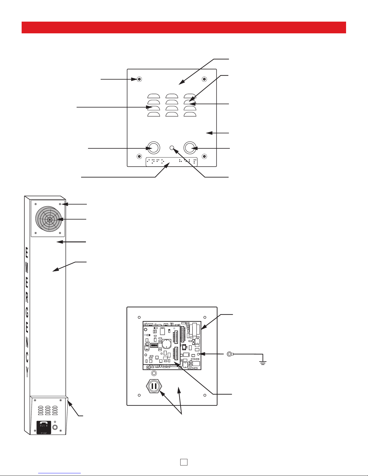
Features Overview
Mounting Screws: (4) T-10 Torx head
stainless steel, flat head, security
screws and drive bit included.
Microphone: Omni-directional
microphone with protective
water-resistant cloth.
“INFO” Push to Call Button
(models
and E-1600A-BLT2EWP
Solid 316 stainless steel
internally sealed per IP67.
E-1600A-AST2EWP
only):
Front View of the
Phone Panel
INFO HELP
CALL
CONNECTED
VIKING©
Faceplate: Marine grade 316 stainless steel.
Speaker: Mylar speaker with rubber
gasket to maintain water-tight seal and
eliminate water deterioration.
Speaker Screen: Speaker screen with
0.018" wide slots to prevent punctures
from paperclips, etc.
Laser Etched Graphics
“HELP” Push to Call Button: Solid 316
stainless steel internally sealed per IP67.
Grade 2 Braille Label
E
M
E
R
G
E
N
Mounting Screws: (4) T-10 Torx head stainless steel,
flat head, security screws and drive bit included.
SL-2 Strobe/Beacon: Blue shatter resistant polycarbonate
lens. Designed to meet IP66 ingress Protection Rating.
Tower Chassis: 8 gauge (0.125” thick) aluminum with
weather-resistant high-visibility yellow powder paint.
EMERGENCY or ASSISTANCE lettered in
black on three sides of the tower chassis.
Rear View of the
Phone Panel
ON
1
2
Ring Connector
Red Call Connected LED
1600A Emergency Phone Board
(included)
C
Y
CALL
CONNECTED
PUSH FOR
HELP
VIKING©
Rain Guard
(included)
ON
1
2
3
* Earth Ground
(optional)
BLK-4 Control Module
Marine grade 316 stainless steel faceplate
and push button switch (sealed per IP67)
3
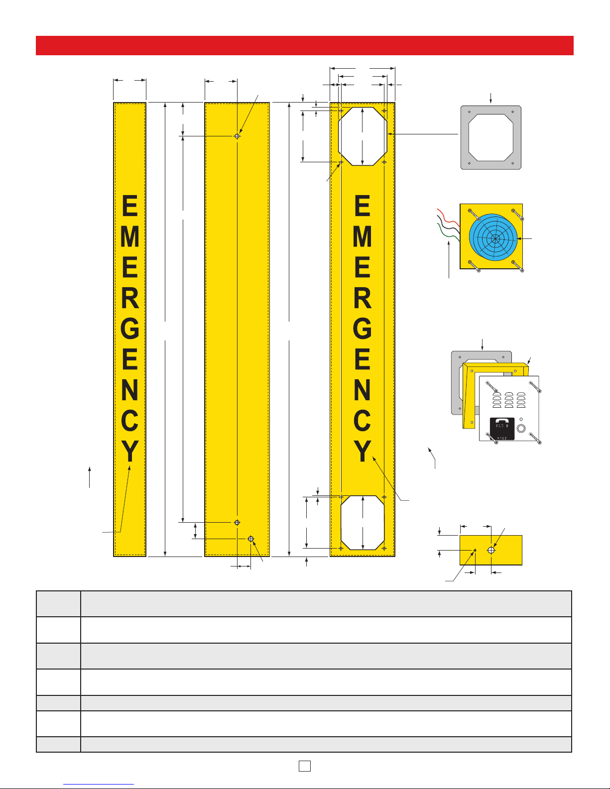
Installation and Specifications
A
Step 1.
Mount the tower phone approximately 42” above the floor to a flat, sturdy surface using 5/16 hardware. Note: Flat
washers should be used on the main mounting bolts for additional strength.
Step 2.
Locate the strobe light panel and attach red, black and green 42” wire extensions with butt connectors then pass the red,
black and green wires from the strobe panel through the gasket and the upper hole in the tower.
Step 3.
Mount the strobe panel to the tower using the four security screws provided. Attention: To make sure water drain notch
between stobe and panel is facing down, attach strobe panel with wires exiting left side of panel.
Step 4.
Locate the phone panel. Using the gel-filled butt connectors, connect the red, black and green wires labeled “Strobe Light”
to the red, black and green wires on the strobe panel.
Step 5. Connect the phone line to the red and green wires (this connection is not polarity sensitive).
Step 6.
Connect the 12V DC adapter wires (-) and (+) to the black with red stripe (-) and red with black stripe (+) wires from the
BLK-4 control module.
Step 7. Mount the phone panel to the tower using the remaining four security screws.
3.0
0.35 Diameter
(2 places)
3.00
3.12
35.760
Use 5/16" bolt
and flat washer
(included)
1.000
0.75
0.325
4.750
Self-clinching
nut 6-32
(8 places)
6.0
4.500
4.000
5.400
0.250
A
Adhere gasket to chassis,
centering over mounting holes
Strobe Panel
S
S
I
S
42.0 in.
(± 0.1)
42.0 in.
(± 0.1)
T
A
N
C
E
“ASSISTANCE”
on models
E-1600A-AST-EWP
E-1600A-AST2EWP
or
“EMERGENCY”
on models
E-1600A-BLT-EWP
E-1600A-BLT2EWP
Side View
1.50
1.25
Back View
0.875 Dia.
4.750
0.75
0.125
5.000
Front View
S
S
Attention: To make sure water drain
notch between stobe and panel is
facing down, attach strobe panel with
I
wire exiting left side of panel.
S
T
A
N
C
E
“ASSISTANCE” on models
E-1600A-AST-EWP
E-1600A-AST2EWP
“EMERGENCY” on models
E-1600A-BLT-EWP
E-1600A-BLT2EWP
1.37
0.125 Diameter
Condensation
Drain Hole
Adhere gasket to chassis,
centering over mounting holes
PUSH FOR
HELP
VIKING
©
Phone
Panel
or
Knockout for
1/2 inch conduit
2.87
1.50
Rain Guard
(included)
CALL
CONNECTED
Bottom
View
SL-2
Strobe/
Beacon
4
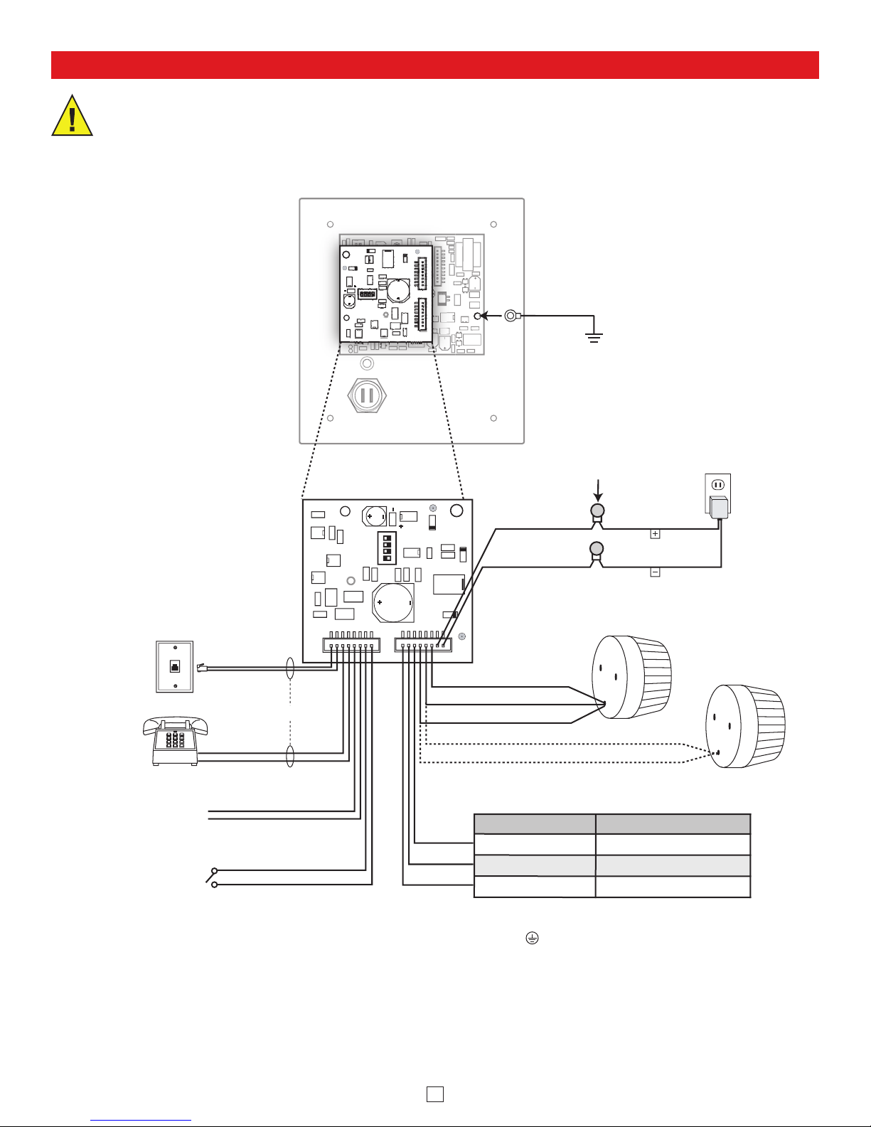
Wiring
3
3
2
ON
* Note: To increase surge protection, loosen the PCB mounting screw labeled (as shown) and fasten a wire with ring connector
(included) from the mounting screw to Earth Ground (grounding rod, water pipe, etc.)
IMPORTANT: Electronic devices are susceptible to lightning and power station electrical surges from both the AC outlet and the
telephone line. It is recommended that a surge protector be installed to protect against such surges.
** Note: The gel-filled (water-tight) butt connectors are designed for insulation displacement on 19-26 gauge wire with a maximum
insulation of 0.082 inches. Cut off bare wire ends prior to terminating.
*** Note: When wires are routed from above, a “drip loop” is recommended to keep water away from the circuit board.
DIP Switch 4 OFF
DIP Switch 4 ON
N.C.
+12VDC Normally ON
COM
+12VDC
N.O.
+12VDC Normally OFF
Rear View of the
Phone Panel
Ring Connector
(included)
* Earth Ground
(optional)
** Gel-Filled Butt
BLK-4 Control
Module (included)
rotated 90°
Connectors (included)
Note: Polarity Sensitive!
(+) Red with
Black stripe
(-) Black with
Red stripe
Positive
Negative
12V DC
Adapter
(included)
120V AC
*** Drip
Loop
Rear View of the SL-2
(included)
Rear View of Legacy
SL-1 Strobe Light
(included with 2012 and older
E-1600A-BLT-EWP models)
Incoming
Analog
Phone Line
Phone or
Terminal
Device
(not included)
Red with
Yellow stripe
Green with
Yellow stripe
Note: Not polarity sensitive.
Brown
Gray
Strobe Light
see Programming page 6
Red (+)
Black (-)
Green (see section F page 6)
Black
Red
Auxiliary Relay Contact Output
Disable Feature
(see section E on page 6)
Trigger Input for Optional
Remote Trigger Switch
(see section G on page 6)
Blue
Blue
White
White
Orange
Purple
Yellow
(see section D on page 5)
5
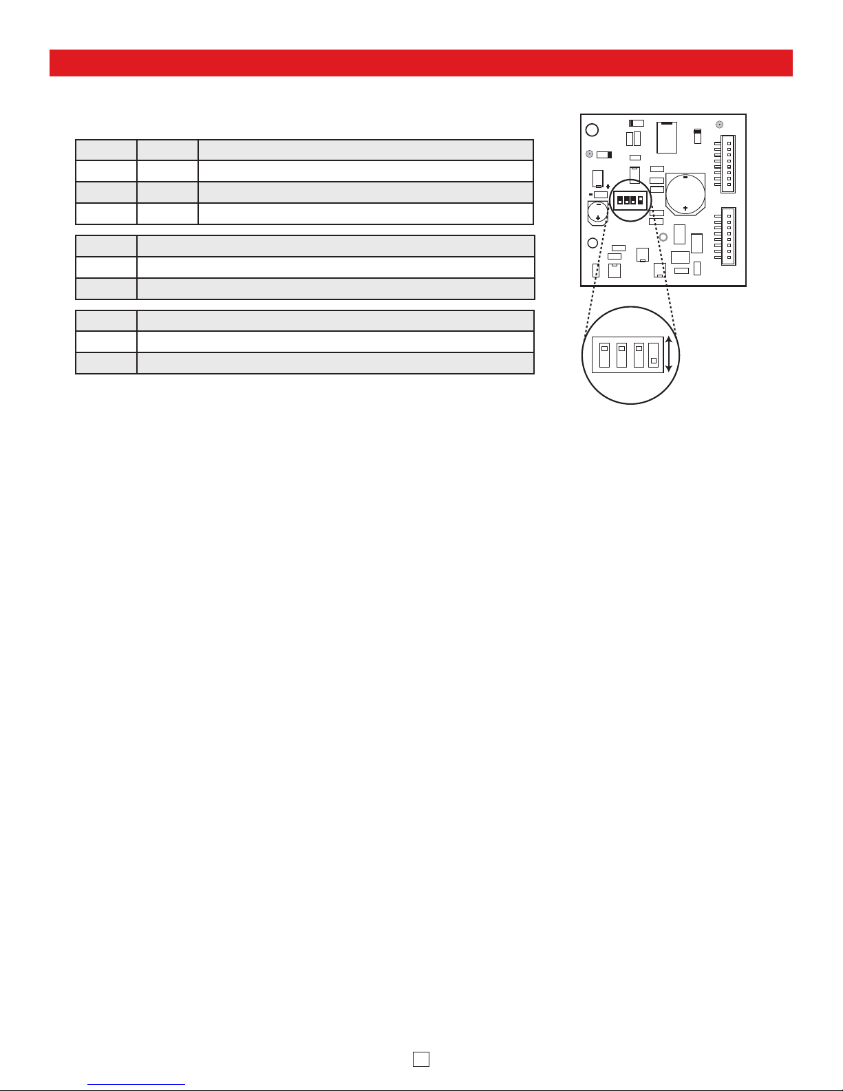
BLK-4 Control Module Programming
Switch 1 Switch 3 Description (see section B)
ON OFF Ring Detection Only
OFF ON Off-Hook/Loop Current Detection Only
ON ON Ring and Off-Hook/Loop Current Detection
Switch 2 Ring Cadence Mode (see section C)
ON Ring Cadence Mode ON - relay remains activated in between rings
OFF Ring Cadence Mode OFF - relay is activated only during ringing
Switch 4 Auxiliary Relay Contacts (see section D)
ON Wet (12VDC, 100mA maximum)
OFF Dry (1 Amp maximum @ 30VDC)
DIP switch 2 is used for switching between different ring detection modes. In the OFF position, the strobe light and
relay will activate only while ring voltage is present and will turn off between rings. In the ON position, the strobe light
and relay will remain on for up to 5.75 seconds after the ringing has stopped. This allows the strobe light and relay to
remain on between rings of a standard ring cadence. Note: To use the Ring Cadence Mode, ring detection MUST be
enabled (DIP switch 1 - ON).
With DIP switch 4 OFF, normally open and normally closed dry relay contacts are available on the orange, purple and
yellow wires. The contacts are rated at .5A @ 125VAC/1A @ 30VDC. If contacts are driving an inductive load, place a
suppression device at the load to snub high voltage spikes.
With DIP switch 4 ON, wet/switched +12VDC (100mA maximum) will be output on the yellow wire and “-” (GND) on the
black wire.
2. Loop/Off-hook Indication Only
Place DIP switch 1 OFF and DIP switch 3 ON. In this configuration, the E-1600A-AST-EWP will only flash the strobe
light while off-hook (while the emergency phone is in use).
1. Ring Indication Only
Place DIP switch 2 on the 1600A phone board in the OFF position (not shown in the diagram - see 1600A Phone
Board Programming section J). Note: With DIP switch 2 in the OFF position, the 1600A emergency phone board
will not answer an incoming call. The BLK-4 control module can monitor for ringing any place along the ringing
line. Place DIP switch 1 ON and DIP switch 3 OFF.
3. Both Ring and Loop/Off-hook Indication
If the application requires ring and loop/off-hook indication, place DIP switch 1 and 3 in the ON position.
A. DIP Switches
B. Configuring for Ring and/or Loop/Off-Hook Indication
C. Ring Cadence Mode
D. Auxiliary Relay Contacts
E. Disable Feature
The “Disable” input can be connected to a switch for remotely disabling/turning off the strobe light and the device
controlled by the auxiliary contacts (camera, etc.). Note: The disable feature on the E-1600A-AST2EWP and E-1600A-
BLT2EWP is factory pre-wired to the “Info” push button. This prevents the strobe from activating when the “Info” push
button is pressed.
BLK-4 Control Module
ON
1
23
4
 Loading...