

Viking VCSB483D, DFSB483D, DDSB483D Service Notebook
VCSB483D# -- DFSB483D# --DDSB483D#
COVER
F90597
SERVICE NOTEBOOK
REFRIGERATION
VCSB483D# -- DFSB483D# -- DDSB483D#
VIKING RANGE CORPORATION, P.O. DRAWER 956, GREENWOOD, MS 38930-USA
F90597

TABLE OF CONTENTS
VCSB483D# with Ice and Water-------------------------------------------------------------------- 4
Cabinet Air Flow-------------------------------------------------------------------------------------- 5
Machine Compartment Air Flow-------------------------------------------------------------------- 6
Refrigerant Flow--------------------------------------------------------------------------------------- 7
Water Flow--------------------------------------------------------------------------------------------- 8
General Specifications-------------------------------------------------------------------------------- 9
Compressor Specifications---------------------------------------------------------------------------- 10
R134a Refrigerant Service Information------------------------------------------------------------- 11
Safety Precautions-------------------------------------------------------------------------------------- 12
Equipment and Tools----------------------------------------------------------------------------- 13-16
Evacuation and Charging--------------------------------------------------------------------------- 17-18
Display Panel Operation------------------------------------------------------------------------------ 19
Alarms--------------------------------------------------------------------------------------------------- 20
Electronic Functional Description------------------------------------------------------------------- 20
Mode A and Mode B----------------------------------------------------------------------------- 21-23
Refrigerator / Freezer Thermister Resistance------------------------------------------------------- 24
Factory Set Freezer / Refrigerator-------------------------------------------------------------------- 24
Reading Temperature Display------------------------------------------------------------------------ 24
Temperature Offset Calibration---------------------------------------------------------------------- 24
Low Voltage Board Check Points------------------------------------------------------------------- 25
High Voltage Board Check Points------------------------------------------------------------------ 26
Wiring Diagram VCSB483# (no Water or Ice in door) Dispenser---------------------------- 27
Wiring Diagram VCSB483D# (Dispenser Model)------------------------------------------------ 28
Variable Capacity Compressor (VCC) Control Unit--------------------------------------------- 29
Speed Control Interface------------------------------------------------------------------------------ 30
Wiring Schematic-------------------------------------------------------------------------------------- 31
Freezer Compartment Theory of Operation-------------------------------------------------------- 32
Refrigeration Compartment Theory of Operation------------------------------------------------- 33
Refrigeration and Freezer Compartment Theory of Operation---------------------------------- 34
Compressor Starting Procedures-------------------------------------------------------------------- 35
Compressor Normal Operation Mode-------------------------------------------------------------- 35
Inverter Shutdown and Protections----------------------------------------------------------------- 36
Adapter Board Logic Flowchart--------------------------------------------------------------------- 37
Control Board Operations----------------------------------------------------------------------------- 38
Troubleshooting Guide------------------------------------------------------------------------------39-40
Ice and Water Dispenser------------------------------------------------------------------------------- 41
Water Filter---------------------------------------------------------------------------------------------- 42
Water Filter Bypass Instructions
Standard Installation-------------------------------------------------------------------------- 43
Water Filter Bypass Instructions------------------------------------------------------------- 44
System Specification and Performance Data Sheet------------------------------------------------ 45
Water Line Connections------------------------------------------------------------------------------- 46
Icemaker-----------------------------------------------------------------------------------------------47-51
3
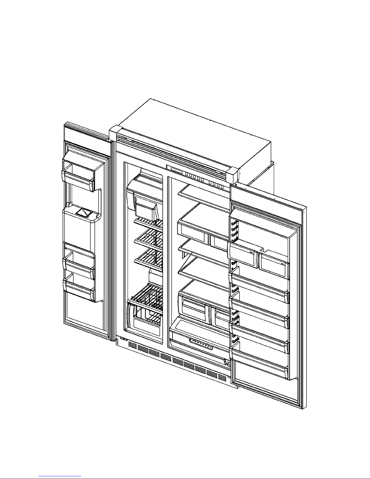
VCSB483D# with ICE and WATER
4
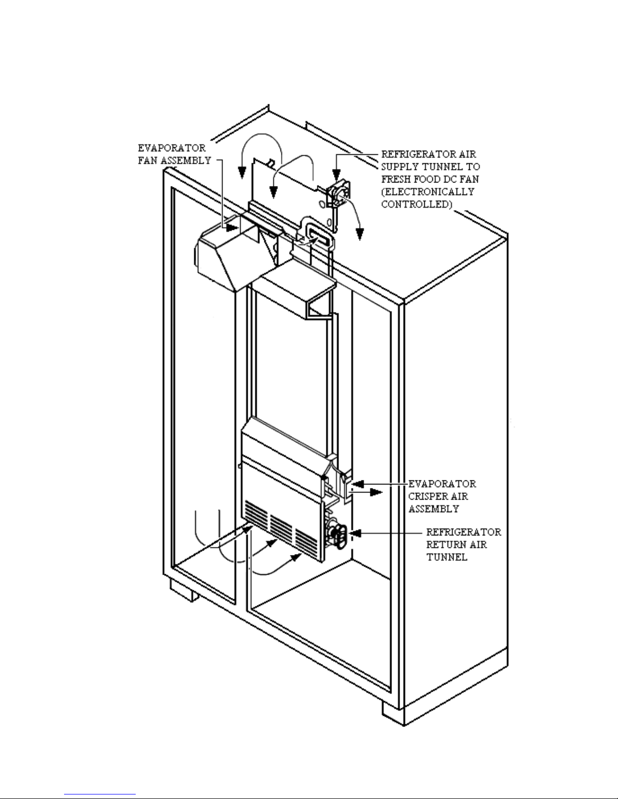
CABINET AIR FLOW
5
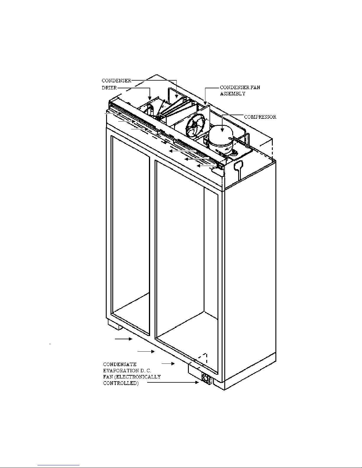
MACHINE COMPARTMENT AIR FLOW
6
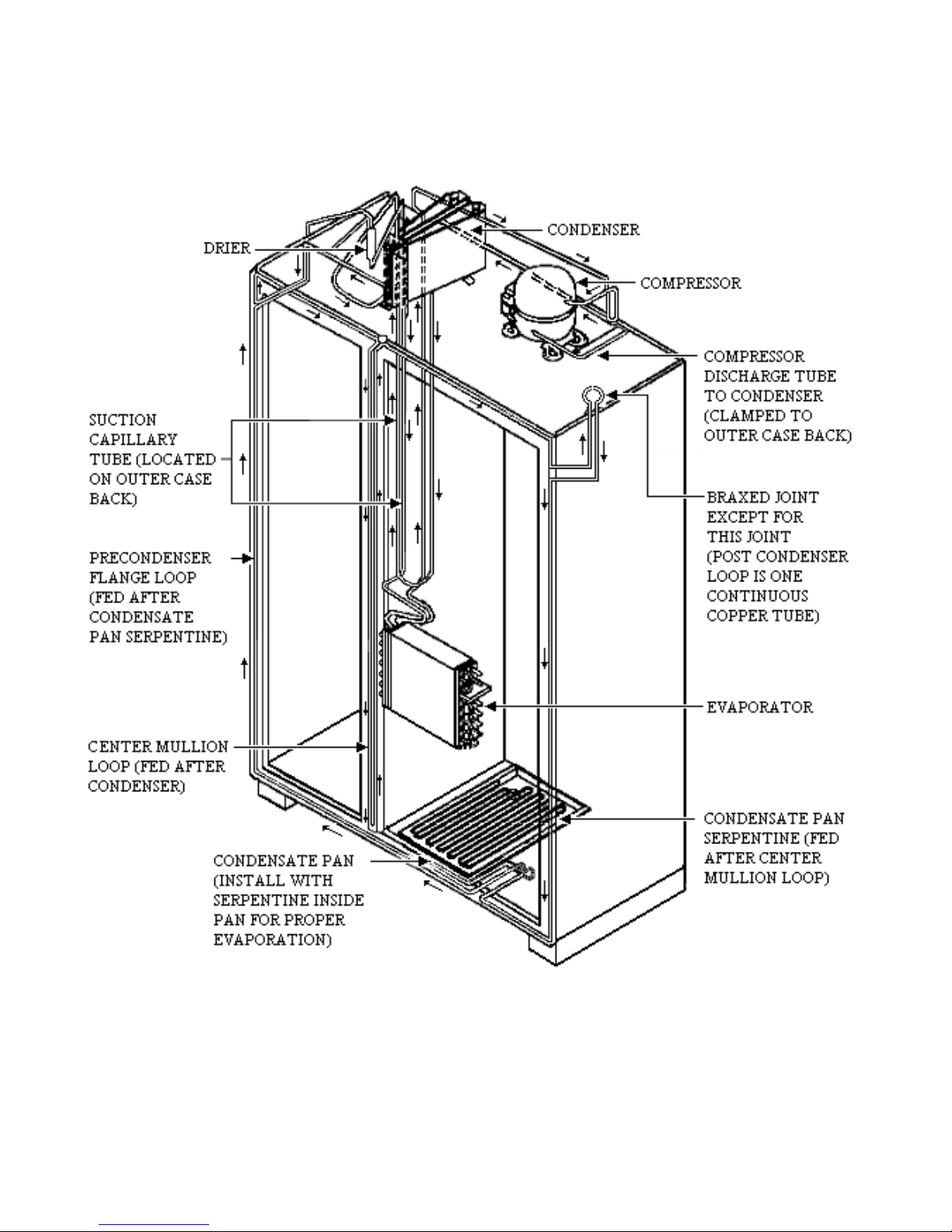
REFRIGERANT FLOW
7

WATER FLOW
8
WARNINGS
To avoid electrical shock, which can cause severe personal injury or death,
disconnect power to refrigerator using power switch before servicing. Wires
removed during disassembly must be replaced on proper terminals to insure correct
grounding and polarization. After servicing, reconnect power using power switch.
DC Compressor – Do Not Connect to 120VAC
9
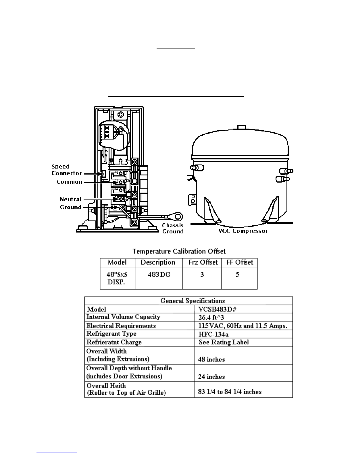
SPECIFICATIONS AND FEATURES
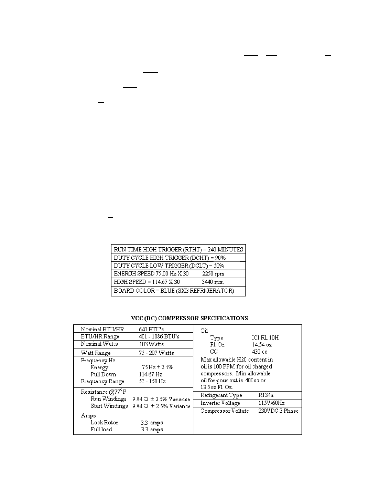
The VCC receives one of 3 signals from the adaptor board: OFF, E frequency, and H
frequency.
OFF STATE CRITERION
The VCC control signal is OFF whenever the voltage drive to the compressor relay is off.
H (HIGH COOLING CAPACITY) STATE CRITERIA
The VCC control signal goes to the H frequency when any of the following conditions are
detected
:
•
The first compressor cycle after power restoration. The high capacity provides a faster
initial pull-down to control temperature
.
• The compressor duty cycle exceeds DCHT, 90%. Once triggered, this mode persists until
the duty cycle drops below DCHX, 50%. A high external ambient increases the duty
cycle.
• Compressor operation for more than 3 hours. The longest normal run time at 90° F is 2.5
to 3 hours. A longer run time implies the user activated the maximum refrigerate or
maximum freeze mode or there is an unusual cooling load. The mode persists until the
duty cycle drops below DCHX.
E (EFFICIENT COOLING STATE CRITERION
The VCC control signal assumes the E state when none of the conditions above for the H state
are valid.
Note: Compressor Speed = Frequency x Motor Constant
10

R134a REFRIGERANT
SERVICE INFORMATION
This product uses R134a refrigerant. This refrigerant requires synthetic Ester Oil in the compressor. This cooling
system does not tolerate contamination from any of the following:
• Other Refrigerants
• Moisture
• Petroleum-based Lubricants
• Silicone Lubricants
• Cleaning Compounds
• Rust Inhibitors
• Leak Detection Dyes
• Any Other Type of Additive
As a result the following precautions should be observed
• Use equipment dedicated to R134a sealed system only.
• Do not leave a replacement compressor open to the atmosphere for more than 10 minutes.
• Always replace the filter-drier when performing any repairs on the sealed system.
• If the rubber plugs on the service replacement compressor appear to have been tampered with or
removed, DO NOT USE THE COMPRESSOR. Get another one.
• The filter-drier MUST be cut from the sealed system. Never un-braze the filter-drier from system
tubing. Applying heat will drive moisture back into the sealed system.
HEALTH AND SAFETY HANDLING 134a
Allowable Overall Exposure Limit 1,000 ppm
Vapor Exposure to Skin No Effect
Liquid Exposure to Skin Can Cause Frostbite
Vapor Exposure to Eyes Very Slight Irritation
Liquid Exposure to Eyes Can Cause Frostbite
Above Minimum Exposure Limit Can Cause Asphyxiation.
Tachycardia and Cardiac
arrhythmias.
Safety and Handling Wear appropriate Skin and
Eye protection. Use
adequate Ventilation.
Spill Management Remove or Extinguish Igni tion or Combustion Sources.
Evacuate or Ventilate Area.
Fire and Explosion Hazards May Decompose if contact
with Flames and Heating
elements. Container May
Explode IF Heated Due to
Pressure Rise. Combus ion Products are Toxic.
Storage Conditions The Procedures/Rules for
R12 also Apply to 134a.
Disposal Procedure Reclaim
11
SAFETY PRECAUTIONS
TREAT LIQUID AND VAPORIZED REFRIGERANT WITH RESPECT. IN CASE OF ACCIDENTAL
RELEASE OF LARGE AMOUNTS OF REFRIGEANT:
Vapors from the refrigerant can reduce the oxygen available for breathing and cause suffocation.
Refrigerant decomposes rapidly and becomes toxic and corrosive when it reaches approximately 1100° F.
Refrigerant can cause skin irritation and frostbite. Always wear gloves and safety glasses or goggles
when working with liquid or vaporized refrigerant.
WHEN WORKING WITH REFRIGERANT, DO NOT:
• Purposely release refrigerants into the environment.
• Inhale refrigerant vapors
• Use refrigerant in a unventilated area
• Allow refrigerant to contact your skin, eyes or clothing.
SAFETY INFORMATION
If refrigerant comes in contact with eyes, flush with fresh water for at least 15 minutes.
If refrigerant comes in contact with exposed skin, flush with fresh water. begin with the water cold and
gradually increase the water temperature to warm the skin slowly.
If refrigerant vapor is inhaled, move to an area of fresh air immediately. If breathing has stopped, give
mouth-to-mouth artificial respiration. If available, give the victim oxygen. Avoid administering
stimulants. Do not give adrenaline (epinephrine). Call a physician immediately.
12
EQUIPMENT AND TOOLS
A separate set of hoses and hand valves must be maintained for use with sealed systems
with R134a refrigerant. Equipment used with CFC refrigerants will contaminate R134a
(HFC) sealed systems.
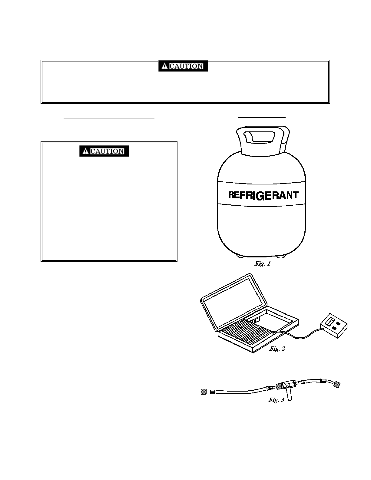
EQUIPMENT DESCRIPTION
Tank of Liquid Refrigerant – Care should be
taken to be sure the proper refrigerant is
available. (Fig. 1)
Handle the tank of liquid refrigerant
properly. The contents of the tank are under
pressure. Observe the following precautions and
DO NOT:
• Drop or handle the tank roughly
• Tamper with any installed safety relief valves
• Store the tank in direct sunlight or in a damp
location.
• Heat the tank above 125° F.
• Refill the tank
Empty tanks should be disposed of properly.
Charging Scale – An electronic or
computerized charting scale measures the
amount of liquid refrigerant charge that is
ispensed into a sealed system. (Fig. 2)
d
The amount of refrigerant dispensed into the
sealed system is indicated on a Liquid Crystal
Display (LCD). The LCD is calibrated in .5
ounces or .01 gram increments or smaller. The
charging scale can be used to monitor the
amount o
ystem.
s
Charging Hose Configuration – One hose 4 to
6 feet long should be attached to a pigtail
consisting of a ball type hand valve with a 45°
threaded fitting. A low-loss adapter should be
onnected to the 45° threaded fitting. (Fig. 3)
c
f refrigerant necessary to back flush a
ILLUSTRATION
13
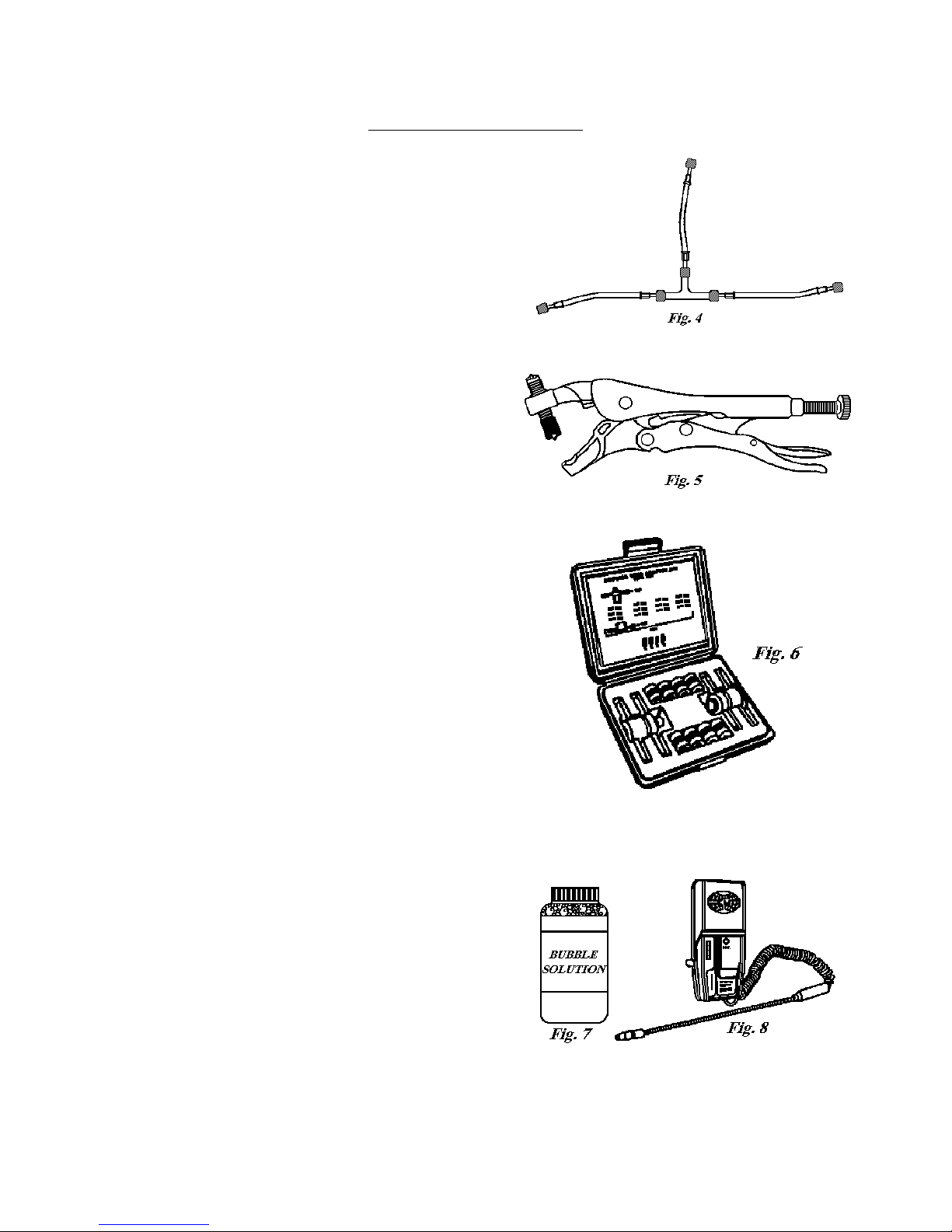
EQUIPMENT DESCRIPTION
Purging Hose Configuration – This arrangement of three
4’ to 6’ hoses with low-loss fittings and a ¼” male flare
Tee fitting can be used to purge a sealed system for both
operating and non-operating compressor situations. No
hand valves are required. (Fig. 4)
Piercing Tool with Access Valve – These access valves
can be installed without the need for brazing and will
not remain on the system when repairs are completed.
(Fig. 5)
Process Tube Adaptor Kit – This kit allows the attachment of
hand valves to various sizes of exposed tubing ends during back
flushing, charging, and/or evacuating a sealed system. (Fig. 6)
Bubble Solution or Electronic Leak Detector – Bubble
solution is the recommended means of checking for highside leaks after repairing a pressurized sealed system. (Fig.
7) An electronic leak detector will also detect the presence
of any refrigerant escaping from the sealed system. (Fig. 8)
14
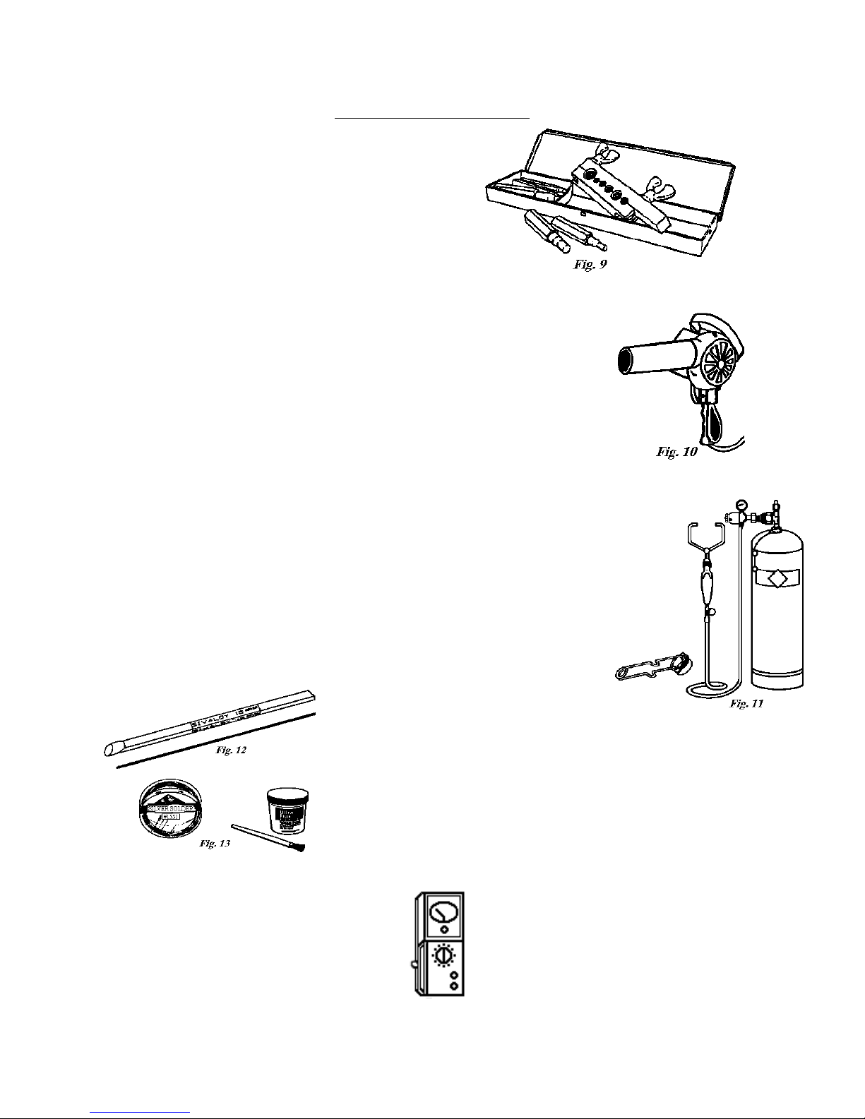
EQUIPMENT DESCRIPTION
Swaging Kit – A swaging tool kit may be needed to
expand system tubing to fit replacement parts. (Fig. 19)
Heat Gun – A heat gun can be used to heat a non-operating compressor or the
evaporator during purge and the refrigerant tank to increase charging pressure.
Many heat guns have a stand that allows continuous operation while other
repairs are made. A heat gun rated at 1500 watts or greater is recommended.
(Fig. 10)
Single MC-Size Fuel Tank of Acetylene with a Double Tip Torch – The
MC-size single fuel tank of acetylene gas is very portable and easy to use. Two
torches are acceptable for use: A double-tip torch heats both sides of the joint
at the same time and is less likely to scorch the inside of the tubing; A singletip Turbo-brand torch equipped with a flame reflector will also heat both sides
of a joint and provide a hotter flame. A striker is used to light the torch.
(Fig.11)
15% Silver Brazing Alloy (Silfos) – Silfos can be used for all
copper to copper sealed system brazing. (Fig. 12) A 45 % silver
solder and flux must be used to braze copper to steel. (Fig. 13)
Frequency Meter
15
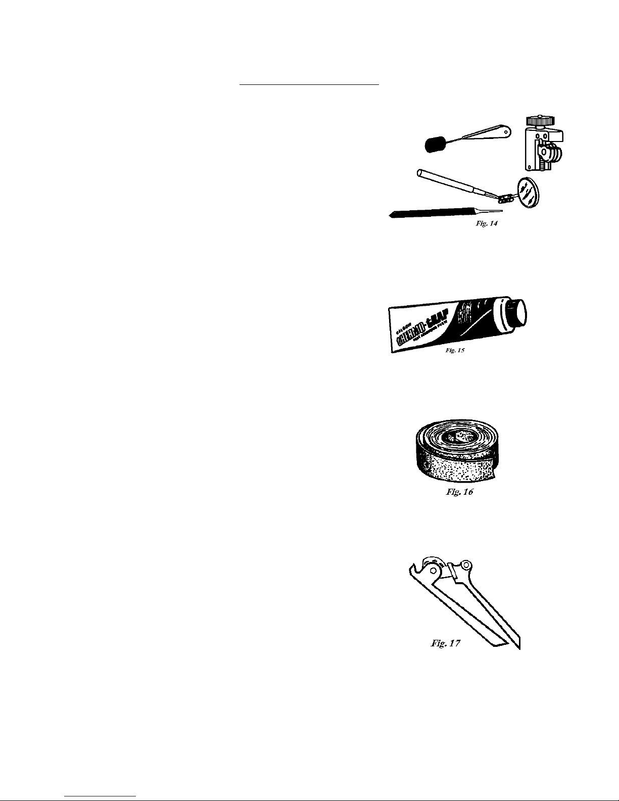
EQUIPMENT DESCRIPTION
Inspection Mirror, Tubing Cutter, Triangular File and Steel
Brush – The inspection mirror should be small enough to
inspect in tight spaces around joints. A mini-cutter will be
required to cut tubing in tight spaces where a standard cutter
will not turn. A triangular file will be needed to score capillary
tubing. A steel brush will be required to clean brazed joints.
(Fig. 14)
Heat Trap Paste – Heat trap paste should be applied to the
tubing between the brazing site and the components or area that
must be protected from high heat. (Fig. 15)
Refrigeration Sanding Cloth – Refrigeration sanding cloth will be
need to clean all tubing ends and other component parts that will be
brazed. Do Not Use Oil Based Sanding Cloth such as Emery
Cloth. (Fig. 16)
Tubing Bender – Used to form system tubing during repairs. (Fig.
17)
16
 Loading...