

Viking Designer Microwave Built-In Trim Kit, DMOS201, DMTK302 Installation Manual
Viking Installation Guide
Designer Microwave Built-In Trim Kit
2
E
Table of Contents
IMPORTANT–Please Read and Follow!
Warnings & Important Information ———————————————————————— 2
Specifications ————————————————————————————————— 3
General Information ——————————————————————————————— 4
Parts Included in the Kit ————————————————————————— 4
Cabinet or Wall Cutout —————————————————————————— 4
Electrical Outlet Location ————————————————————————— 4
Installation ——————————————————————————————————— 5
Mounting Template ——————————————————————————— 5
Bottom Duct Assembly —————————————————————————— 6
Mounting Bracket Assembly ——————————————————————— 6
Cabinet Installation ——————————————————————————— 7
Frame Assembly ————————————————————————————— 7
Side Decoration Assembly (For Surface Mount Only) ————————————— 8
Over Oven Installation —————————————————————————— 8
Performance Checklist ————————————————————————————— 8
Before beginning, please read these •
instructions completely and carefully.
Be sure to DISCONNECT THE PLUG of the •
microwave oven from the electrical outlet
before installing the built-in trim kit. Remove
the turntable from the oven cavity.
Because the kit includes metal parts, caution •
should be used in handling and installation
to avoid the possibility of injury.
Do not remove permanently affixed labels, •
warnings, or plates from the product. This
may void the warranty.
Please observe all local and national codes •
and ordinances.
The installer should leave these instructions •
with the consumer who should retain for local
inspector’s use and for future reference.
WARNING
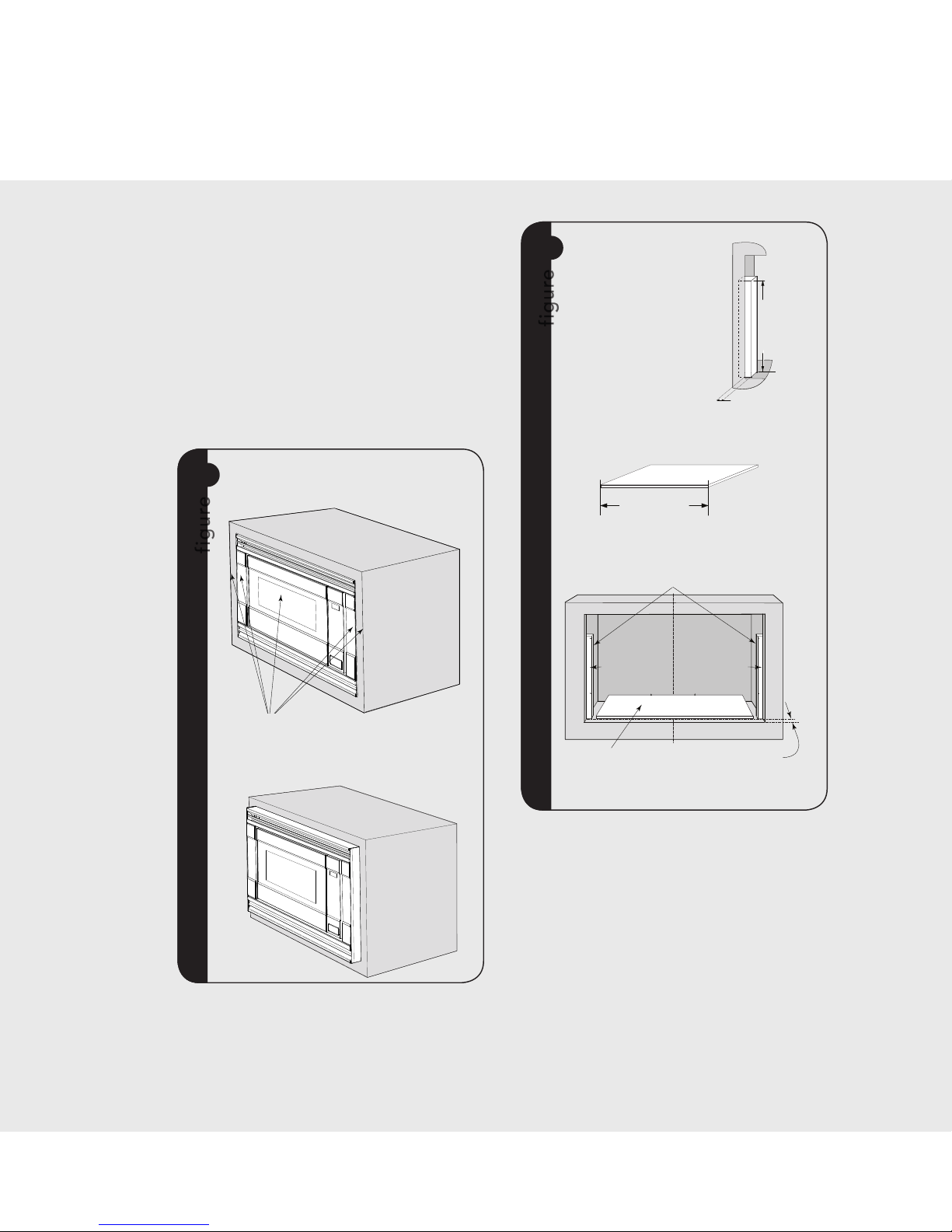
This built-in trim kit is designed for use ONLY
with V iking microwave ovens specifying builtin trim kit DMTK302 on the rating label on t he
left side wall of the oven cavity.
E
3
Microwave Oven Built-In Trim Kit
DMOS201 DMTK302
Overall Width 24" (60.9 cm) 29-1/2" (74.9 cm)
Overall Height from Bottom 13-3/8" (33.9 cm) 17-1/4" (43.7 cm)
Overall Depth from Rear 19-1/8" (48.7 cm)
NA
Oven Interior Width
Height
Depth
Overall
17-3/8"
10-1/2"
18-5/8"
2.0 cu. ft.
(44.1 cm)
(26.6 cm)
(47.3 cm)
NA
Electrical Requirements 120VAC/60 Hz NA
Max. Amp Usage 1.5 KW 13 amps NA
Approx. Shipping Wt. 46 lbs. (20.9 kg) 15 lbs. (6.9 kg)
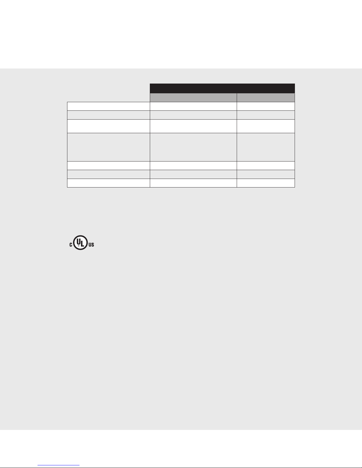
In compliance with standards set by:
FCC – Federal Communications Commission Authorized.
DHHS – Complies with Department of Health and Human Services (DHHS) rule, CFR, Title 21,
Chapter I, Subchapter J.
– This symbol on the Rating label means the product is listed by Underwriters
Laboratories, Inc. for use in USA or Canada.
Specifications
4
E
General Information
4
E
14-1/4" (361.95 mm)
Minimum Cutout Opening Width 27-3/4" (704.9 mm)
Minimum Cutout Opening Height 16-9/16" (420.7 mm)
Maximum Cutout Opening Height 16-13/16" (427 mm)
Maximum Cutout Opening Width 28" (711.2 mm)
Distance between holes 9.1" (231.2 mm)
14" (355.6 mm)
Center Line
Floor Line of Cutout Opening
BUILT-IN TRIM KIT
SURFACE MOUNTING TEMPLATE
FOR DESIGNER SERIES MICROWAVE OVEN
1. Align the Surface Mounting Template center line with the
center of the cabinet. Align the Floor Line with the bottom
of the cabinet at the desired height. Tape it into place.
2. Predrill 4 holes marked with a 5RQE" drill bit.
3. Cut the cabinet opening between the minimum and
maximum cutout opening lines. Be careful to cut precisely
along the Floor Line of the cutout.
4. Remove template from the cabinet.
3-15/16" (100 mm)
7
4-3/16" (106.4 mm)
FLOOR LINE OF CUTOUT OPENING
BUILT-IN TRIM KIT
FLUSH MOUNTING TEMPLATE
FOR DESIGNER SERIES MICROWAVE OVEN
CABINET CUTOUT LINE
CABINET CUTOUT LINE
CENTER LINE
SIDE SPACER TEMPLATE - L
SIDE SPACER TEMPLATE - R
FIGURE 1
Cutout Opening Height 17-5/16" (439.8 mm)
CABINET CUTOUT LINE
FIGURE 3
14" (355.9 mm)
Distance between holes 9.1" (231.2 mm)
Cutout Opening Width 29-5/8" (752.5 mm)
14-13/16" (376.2 mm)
FIGURE 2
8
2
3
(SURFACE MOUNTING ONLY)
6
1
1) Frame Assembly: QTY 1 2) Bottom Duct Assembly: QTY 1
4
5
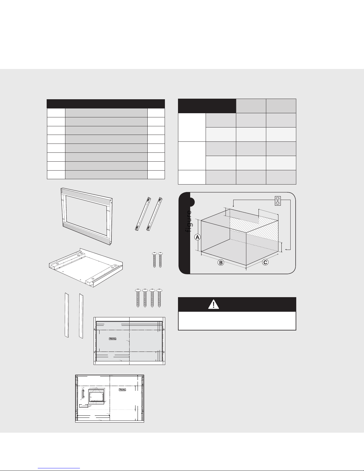
Parts Included in the Kit
Item Part Name QTY
1
Frame Assembly 1
2
Bottom Duct 1
3
Mounting Bracket 2
4
Screw A :1-3/16" length 2
5
Screw B: 1-3/4" length 4
6
Side Decoration
(Surface Mount Only)
2
7
Surface Mounting Template 1
8
Flush Mounting Template 1
Electrical Outlet Location
CAUTION
Outlet should NOT be in the shaded area as
indicated on figure 1.
1
figure
4"(10.2 cm)
4"(10.2 cm)
6"(15.2 cm)
NOTES:
If the Depth (C) dimension is greater than 21" •
(53.3 cm), the outlet location may be in any
area on the rear wall.
The floor of the opening should be constructed •
of plywood strong enough to support the weight
of the oven and floor load (approximately 100
pounds). The floor should be level for proper
operation of the oven. Be sure to check the
local building code as it may require that the
opening b e enclosed wit h side, ceili ng and re ar
partition. The proper functioning of the oven
does not require the enclosure.
Cabinet or Wall Cutout
Cutout Dimensions
Flush
Mount
Surface
Mount
Height A
Minimum
17- 5/16"
(4 39.8 mm)
16-9/16"
(420.7mm)
Maximum
N/A 16-13/16"
(427mm)
Width B
Minimum
29-5/8"
(752.5mm)
27-3/4"
(704.9mm)
Maximum
N/A 28"
( 711. 2m m)
Depth C
Minimum
20"
(503mm)
20"
(503mm)
5
E
13/16" min.
15/16" max.
13-1/2" min.
24" min. width
27-7/8" max. width
1-9/16" (39.7 mm)
BOTTOM and SIDE
SPACER (R and L) offset
EDGES TO ALIGN SIDE SPACER
TEMPLATES (R and L)
Side Spacer (L) Side Spacer (R)
BOTTOM SPACER
CENTERED with
CABINET CUTOUT
3
figure
A
SIDE SPACER—2
REQUIRED. Must
protrude from edge of
cabinet cutout towards
center as shown.
B
BOTTOM SPACER—1
REQUIRED. 1/4" plywood.
C
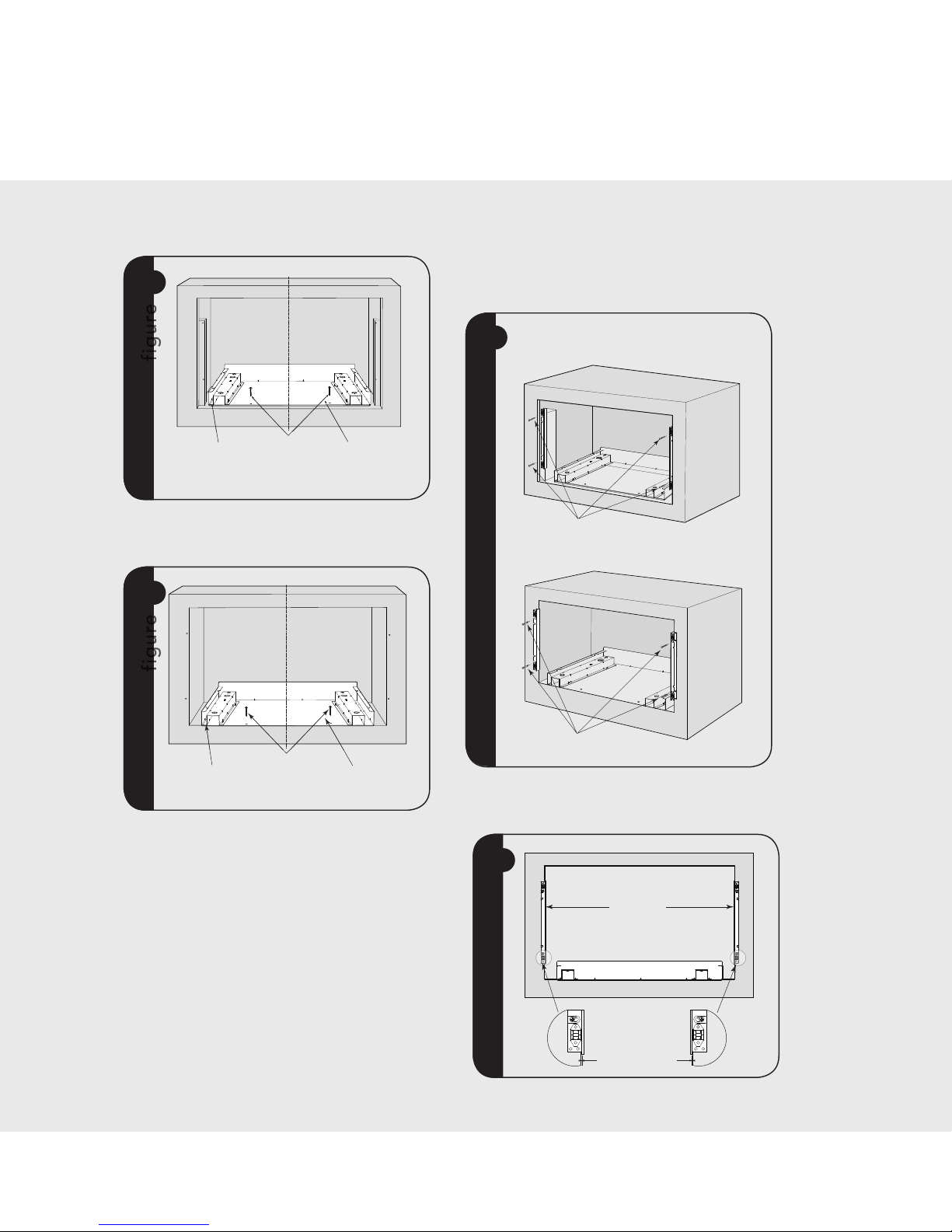
For FLUSH MOUNT, two (2) side spacers and one (1) bottom
spacer are required. Spacers are not included in the kit and
must be fabricated by installer. See figures 3A and B for
spacer requirements. Make sure that all three spacers are
offset from the front of the cabinet by 1-9/16".
Cut out the Side Spacer Templates (R and L)
from the Flush Mounting Template. Align the
indicated edges to the corresponding right and
left side spacers as shown in figure 3. Make sure
to align the bottom edges of the side spacer
templates to the floor of the cabinet opening.
Predrill two (2) holes marked “A” on Side Spacer
Template – R and two (2) holes marked “B” on
Side Spacer Template – L with 1/16" drill bit.
Remove templates from the cabinet.
Installation
Mounting Template
Determine which mounting method to use
based on the required configuration. See figure
2A for FLUSH MOUNT and 2B for SURFACE
MOUNT.
Align the template corresponding to the required
mounting method to the center of the cabinet.
Make sure that the template is level with the
floor. Tape it into place. Cut the cabinet opening
along the lines specified on the template. Leave
template taped in place.
For SURFACE MOUNT, predrill 4 holes marked “A” with a
1/16" drill bit. Remove template from the cabinet. Go to
Bottom Duct Assembly.
2
figure
A
FLUSH MOUNT CONFIGURATION—
Microwave Oven and Frame Assembly glass
are flush with the cabinet.
B
SURFACE MOUNT CONFIGURATION
—Microwave Oven and Frame Assembly
protrude from the surface of the cabinet.
b. Surface Mount Configuration -
Microwave Oven and Frame Assembly
protrude from the surface of the cabinet.
Illustration 2
a. Flush Mount Configuration -
Microwave Oven and Frame Assembly
glass are flush with the cabinet
Indicated surfaces are flush.
6
E
Installation
Bottom Duct Assembly
4
figure
CENTER THE
BOTTOM DUCT
Illustration 6 - for Flush Mount
SCREW A
BOTTOM DUCT
MAKE BOTTOM FLANGE
FLUSH WITH BOTTOM
SPACER
Place the Bottom Duct in the cabinet opening. For FLUSH
MOUNT, it will rest on the bottom spacer centered with
the cabinet. See figure 4.
5
figure
Illustration 7 - for Surface Mount
CENTER THE
BOTTOM DUCT
SCREW A
BOTTOM DUCT
MAKE BOTTOM FLANGE
FLUSH WITH CABINET
For SURFACE MOUNT, the Bottom Duct will rest on the
floor of the opening. See figure 5.
Align the Bottom Duct to the center of the
opening with the bottom flange securely flush
with the bottom spacer (for FLUSH MOUNT) or
the cabinet (for SURFACE MOUNT).
Secure the Bottom Duct Assembly with the two (2)
SCREWS A. See figures 4 and 5 respectively.
Mounting Bracket Assembly
Position the mounting brackets to align with the
predrilled holes that were drilled with the mounting
template.
SCREW B
SCREW B
A
B
FLUSH MOUNT BRACKET
figure
figure
6
SURFACE MOUNT BRACKET
The enclosed ends of the mounting brackets should face
inwards. Check that they are vertical and then secure loosely
with four (4) Screws B. See Figure 6.
figure
figure
7
27-1/2"
(698.5mm)
EQ. EQ.
7
E
Installation
Align the mounting brackets horizontally by sliding
them back and forth along the screw slots until
the brackets are exactly 27-1/2" apart and equal
distance from the cabinet sides. See figure 7.
Once the brackets are correctly positioned,
securely tighten the four (4) screws B.
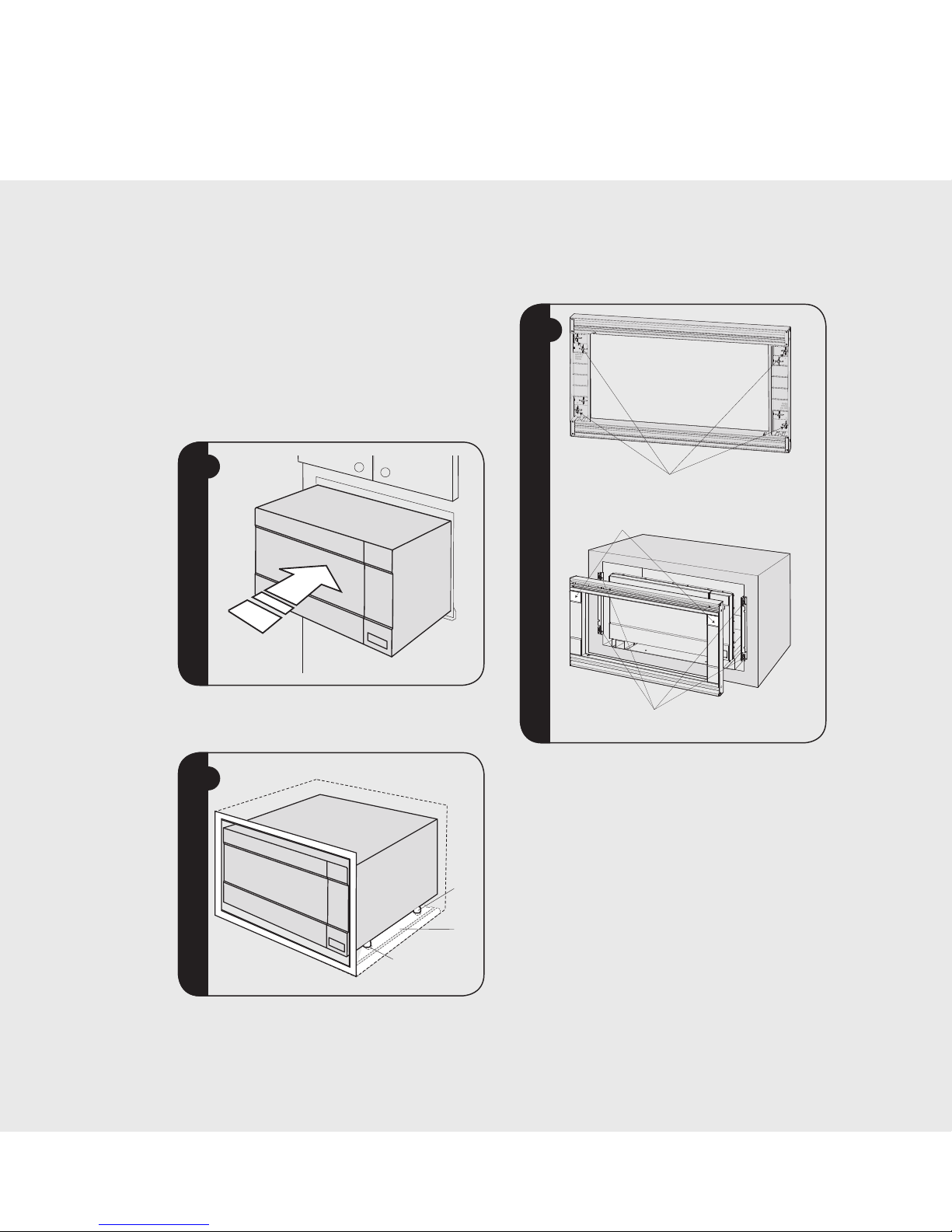
Cabinet Installation
Place the oven adjacent to the wall or cabinet
opening. Plug the power cord into the electrical
outlet.
figure
figure
8
Carefully guide the assembled oven into the prepared
opening. Slide the oven onto the Bottom Duct Assembly.
See figure 8.
figure
figure
9
CABINET INSTALL FRAME INSTALL CABINET INSTALL
BOTTOM
DUCT
ASSEMBLY
FOOT
DUCT RECESS
Avoid pinching the cord between the oven and the wall.
Adjust the position of the oven so that the feet of the oven
are fitted into the recesses of the Bottom Duct Assembly.
S
ee figure 9.
Frame Assembly
Turn over FRAME ASSEMBLY to locate the 4 ball
studs.
Position the FRAME ASSEMBLY with the small
stainless decorations on top. Align the 4 ball studs
with the 4 snap attachments at both ends of the
MOUNTING BRACKETS.
Secure the FRAME ASSEMBLY by firmly pushing
it onto the Mounting Brackets engaging the four
(4) snap attachments. See Figure !.
figure
figure
!
SNAP ATTACHMENT LOCATIONS ON
MOUNTING BRACKETS
SMALL STAINLESS DECORATIONS ON TOP
4 BALL STUDS ON BACK OF FRAME ASSEMBLY
F20685
TINSLB005MRR1
Viking Range Corporation
111 Front Street
Greenwood, Mississippi 38930 USA
(662) 455-1200
For product information
call 1-888-VIKING1 (845-4641)
or visit the Viking Web site at
vikingrange.com
8
E
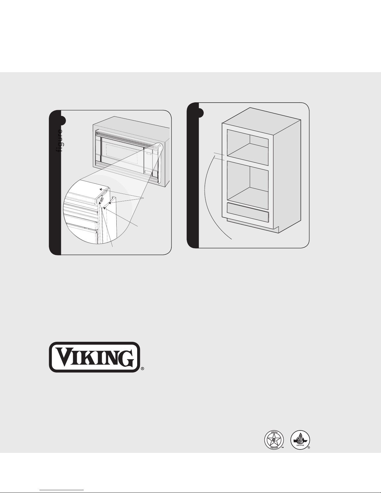
Over Oven Installation
figure
figure
#
2" (5.1 CM) FOR 30" W LOWER OVEN
Performance Checklist
Make sure the unit has been installed according 1.
to all of the Installation Instructions and the
required Mounting Template.
Plug in the power cord.2.
Keep the Use & Care Manual and Installation 3.
Manual.
Installation
Side Decoration Assembly
(For Surface Mount Only)
Peel the backing off the tape on the backside of
the SIDE DECORATIONS. Align the front inner
edge of the side decorations to the front side
edge of the FRAME ASSEMBLY.
Align the top surface of the side decorations to
the top surface of the FRAME ASSEMBLY. Secure
the side decorations by pressing them firmly
against the side of the FRAME ASSEMBLY. See
Figure ".
"
figure
ALIGN TOP
SURFACE OF SIDE
DECORATION TO
TOP SURFACE OF
FRAME ASSEMBLY
FRONT INNER EDGE
OF SIDE DECORATION
FRONT SIDE EDGE OF FRAME ASSEMBLY
 Loading...