

Viking VCBF136, VCFF136, DDFF136 Service Manual
Service
Manual
7KLV PDQXDO LV to be XVeG b\ TXDOL¿eG DSSOLDQce tecKQLcLDQV oQO\
9LNLQJ GoeV Qot DVVXPe DQ\ reVSoQVLbLOLt\ Ior SroSert\ GDPDJe
or SerVoQDO LQMXr\ Ior LPSroSer VerYLce SroceGXreV GoQe b\ DQ
XQTXDOL¿eG SerVoQ
Freestanding
Bottom-Mount and
French Door
3reIerreG SerYLce
7KLV %DVe MDQXDO coYerV JeQerDO DQG
VSecL¿c LQIorPDtLoQ LQcOXGLQJ, bXt Qot
OLPLteG to tKe IoOOoZLQJ PoGeOV
Bottom-Mount
Refrigerator
VCBF136
VCFF136
DDFF136
SMR-0013
October, 2011

Table of Contents
Description Page
Important Information .................................................. 3
Safety Information ........................................................ 3
GENERAL INFORMATION
Specifications ............................................................... 4
Warnings ....................................................................... 5
Model – Serial Number Matrix ..................................... 6
OPERATION
Using the Controls ........................................................ 7
Temperature Controls ................................................... 7
Adjusting Controls ........................................................ 7
Adjusting Set Point Temperatures ................................ 8
Options ......................................................................... 8
User Settings ................................................................0
Ice Maker and Ice Storage Bin ...................................10
Water Filtration System .............................................. 11
Cleaning ..................................................................... 11
DIAGNOSTICS
Main Control Menu ....................................................12
Entering Programming Mode ..................................... 12
Defrost Operation ......................................................15
Entering Forced Defrost Mode...................................16
Entering Service Test Mode........................................ 17
Service Tests ............................................................... 18
101 Defrost Heater and Defrost Circuit .................... 18
102 Compressor/Condenser Fan ............................. 18
112 Freezer Fan ........................................................ 18
121 Damper Operation ............................................ 19
131 Mullion Heater ................................................... 19
141 Fresh Food Thermistor ...................................... 19
142 Freezer Thermistor ............................................19
143 Machine Compartment Thermistor ................... 20
151 Fresh Food Door State ...................................... 20
152 Freezer Door State ............................................ 20
174 Water Actuator Internal Dispenser .................... 20
181 Keypad Operation ............................................. 21
182 Keypad Operation ............................................. 21
191 Ice Maker Valve ................................................. 21
201 Mullion Heater Override .................................... 21
202 Default Defrost Operation ................................. 22
211 Fresh Food Temperature Offsets ....................... 22
212 Freezer Temperature Offsets ............................. 22
221 Reset Default Settings ....................................... 22
231 Water Filter Usage ............................................. 23
232 Water Filter Days In Use .................................... 23
241 Software Revision Main Control ........................ 23
242 Software Revision Display Board ...................... 23
Description Page
Main Control Board Wiring Connections ................... 26
Parts Location–Refrigerator ........................................ 27
Refrigerator Light Bulb ............................................... 28
Refrigerator Light Housing ......................................... 28
Control Board ............................................................. 29
Refrigerator Temperature Sensor ...............................30
Vegetable/Meat Temperature Control .......................30
Refrigerator Light Switch ............................................ 31
Water Tank .................................................................. 31
Water Dispenser ......................................................... 32
Refrigerator Damper................................................... 33
Water Filter ................................................................. 33
Water Flow .................................................................34
Parts Location–Freezer ............................................... 35
Freezer Drawer Switch ................................................ 36
Freezer Light Bulb ...................................................... 36
Freezer Light Housing ................................................ 36
Freezer Drawer, Baskets and Glide Adapters ............. 37
Ice Maker .................................................................... 40
Freezer Thermistor .....................................................43
Evaporator Cover .......................................................44
Evaporator Fan ........................................................... 44
Defrost Heater ............................................................ 45
Defrost Thermostat..................................................... 47
Parts Location–Rear .................................................... 48
Main Control Board .................................................... 49
Overload Relay ........................................................... 50
Condenser Fan ........................................................... 50
Water Valve ................................................................. 51
Troubleshooting ......................................................... 52
WIRING DIAGRAMS
Full Schematic ............................................................55
Wiring Diagram ..........................................................56
SERVICE DIAGNOSTICS AND PROCEDURES
Parts Location–Control Board and
Main Control Board .................................................. 24
Component Testing Control Boards ........................... 25
© 2011 Viking Preferred Service
2
Important Information
SAVE THESE INSTRUCTIONS
REVIEW ALL SERVICE INFORMATION IN THE APPROPRIATE SERVICE MANUAL AND
TECHNICAL SHEETS BEFORE BEGINNING REPAIRS.
Pride and workmanship go into every product to provide our customers with quality appliances. It is possible,
however, that during the lifetime of a product, service may be required. Products should be serviced only by
a qualified authorized service technician who is familiar with the safety procedures required to perform the
repair and is equipped with the proper tools, parts, testing instruments, and the appropriate service manual.
Safety Information
We have provided many important safety messages
throughout this manual and on the appliance.
ALWAYS read and obey all safety messages. This is
a safety alert symbol.
All safety messages will identify the hazard, tell
you how to reduce the chance of injury, and inform
you what can happen if the instructions are not
followed.
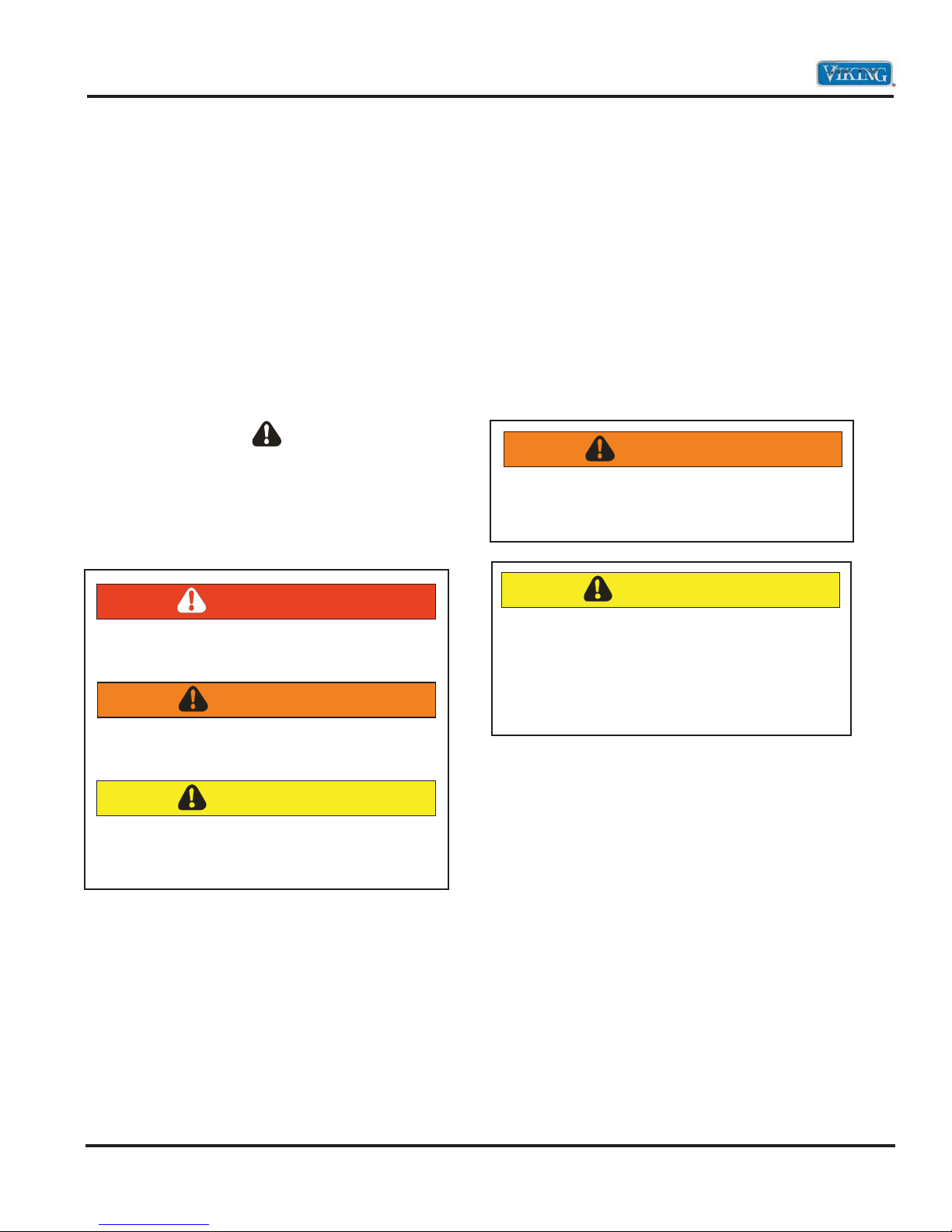
This symbol alerts personnel to hazards that can
kill or hurt you and others. All safety messages will
be preceded by a safety alert symbol and the word
“DANGER”, “WARNING” or “CAUTION”. These
words mean:
DANGER
Immediate hazards which WILL result in severe
personal injury or death.
WARNING
Hazards or unsafe practices which COULD
result in severe personal injury or death.
CAUTION
Hazards or unsafe practices which COULD
result in minor personal injury, product or
property damage.
WARNING
To avoid risk of serious injury or death,
repairs should not be attempted by
unauthorized personnel.
CAUTION
VIKING will not be responsible for any injury
or property damage from improper service
procedures. If performing service on your
own product, you must assume responsibility
for any personal injury or property damage
which may result.
To locate an authorized service agent, call:
Viking Customer Service
Phone No. 1-888-845-4641
Address your written correspondence to:
Viking Preferred Service
1803 HWY 82 West
Greenwood, MS 38930
© 2011 Viking Preferred Service
3
General Information
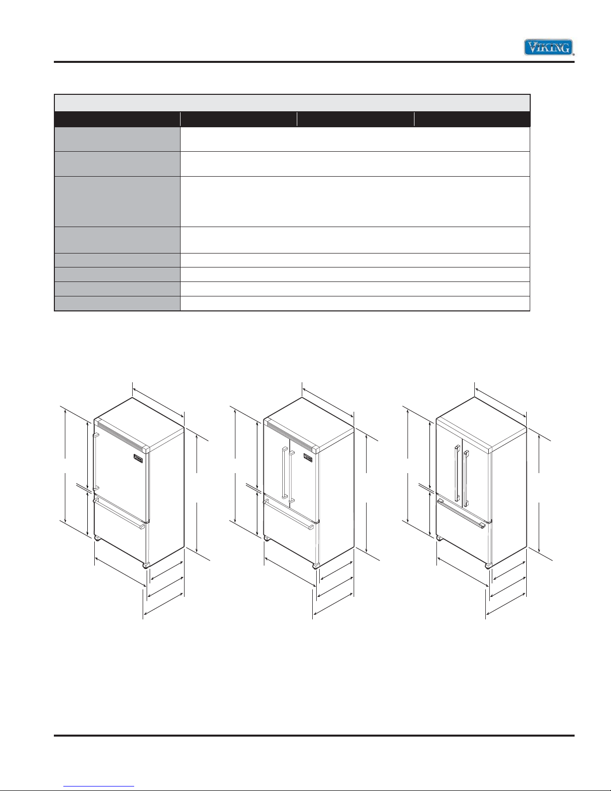
Specifications*
36” Bottom-Mount
Description VCBF136 VCFF136 VDDF136
Overall width
Addition of side panels
Overall height from bottom
Addition of top grilles
70-1/8” (178.1 cm) min. to 70-7/8” (180.0 cm) max.
71-7/8” (182.6 cm) min. to 72-5/8” (184.5 cm) max.
Overall depth from rear
To front edge of side trim
To front of top grille
To front of handle end-cap
Electrical requirements
115 volt, 60 Hz, 15 amp dedicated circuit; 3-wire cord with
Maximum amp usage
Refrigerant type
Refrigerant charge
Appr
oximate shipping weight
*Go to vikingrange.com for latest specifications.
grounded 3-prong plug attached to product
35-5/8” (90.5 cm)
35-7/8” (91.1 cm)
23-1/2” (59.7 cm)
26-1/8” (66.3 cm)
28-1/8” (71.4 cm)
7.9 amps
HFC-134a
See rating label
327 lbs. (148.7 kg)
VCBF136 VCFF136 DDFF136
70-1/8”
(178.1 cm)
41-1/8”
(104.5 cm)
24”
(61.0 cm)
35-5/8”
(90.5 cm)
35-7/8”
w/side panel accessory
(91.1 cm)
23-1/2”
(59.7 cm)
26-3/4”
(67.9 cm)
28-3/4”
(73.0 cm)
71-7/8”
(182.6 cm
wtih top
grille/top
accessory
70-1/8”
(178.1 cm)
41-1/8”
(104.5 cm)
24”
(61.0 cm)
35-5/8”
(90.5 cm)
35-7/8”
w/side panel accessory
(91.1 cm)
23-1/2”
(59.7 cm)
26-3/4”
(67.9 cm)
28-3/4”
(73.0 cm)
71-7/8”
(182.6 cm
wtih top
grille/top
accessory
70-1/8”
(178.1 cm)
41-1/8”
(104.5 cm)
24”
(61.0 cm)
35-5/8”
(90.5 cm)
w/side panel accessory
35-7/8”
(91.1 cm)
23-1/2”
(59.7 cm)
26-3/4”
(67.9 cm)
28-3/4”
(73.0 cm)
71-7/8”
(182.6 cm
wtih top
grille/top
accessory
© 2011 Viking Preferred Service
4

General Information
Warnings
Read and follow all instructions before using this
appliance to prevent the potential risk of fire,
electric shock, personal injury, or damage to the
appliance as a result of improper usage of the
appliance. Use appliance only for its intended
purpose as described in this manual.
To ensure proper and safe operation: appliance
must be properly installed and grounded by a
qualified technician. DO NOT attempt to adjust,
repair, service, or replace any part of your appliance
unless it is specifically recommended in this manual.
All other servicing should be referred to a qualified
servicer.
Make sure that incoming voltage is the same as
unit rating. An electric rating plate specifying
voltage, frequency, wattage, amperage, and phase
is attached to the product.
Electrical Requirements
Assure that the electrical installation is adequate
and in conformance with the National Electrical
Code, ANSI/NFPA 70-latest edition or Canadian
Electrical Code C22.1-1998 and C22.2 No. 0-M91
(or latest edition), and all local codes and
ordinances. A 115 volt, 60-Hz, 15 amp, fused,
electrical supply is required. It is required that
a separate circuit serving only this appliance be
provided. This appliance is equipped with a power
supply cord having a 3-prong grounding plug.
To minimize possible shock hazard, the cord must
be plugged into a mating 3-prong, grounding-type
wall receptacle. DO NOT use an extension cord.
WARNING
TIP OVER HAZARD
Appliance is top heavy and tips easily when not
completely installed. Keep doors closed until
appliance is completely installed and secured
per installation instructions.
Use two or more people to move and install
appliance. Failure to do so can result in death
or serious injury.
WARNING
ELECTRICAL SHOCK HAZARD
Disconnect power or turn power disconnect
switch to “OFF” position before removing top
grille. Failure to do so can result in death or
electrical shock.
WARNING
ELECTRICAL SHOCK HAZARD
Plug into a grounded 3-prong outlet. If a
2-prong wall receptacle is encountered,
contact a qualified electrician.
DO NOT remove ground prong.
Unit must be grounded at all times.
DO NOT use an adapter.
DO NOT use an extension cord.
Failure to follow these instructions can result in
death, fire, or electrical shock.
© 2011 Viking Preferred Service
WARNING
BURN HAZARD
DO NOT touch condenser coils near defrost
pan. Doing so can result in burns.
5
General Information
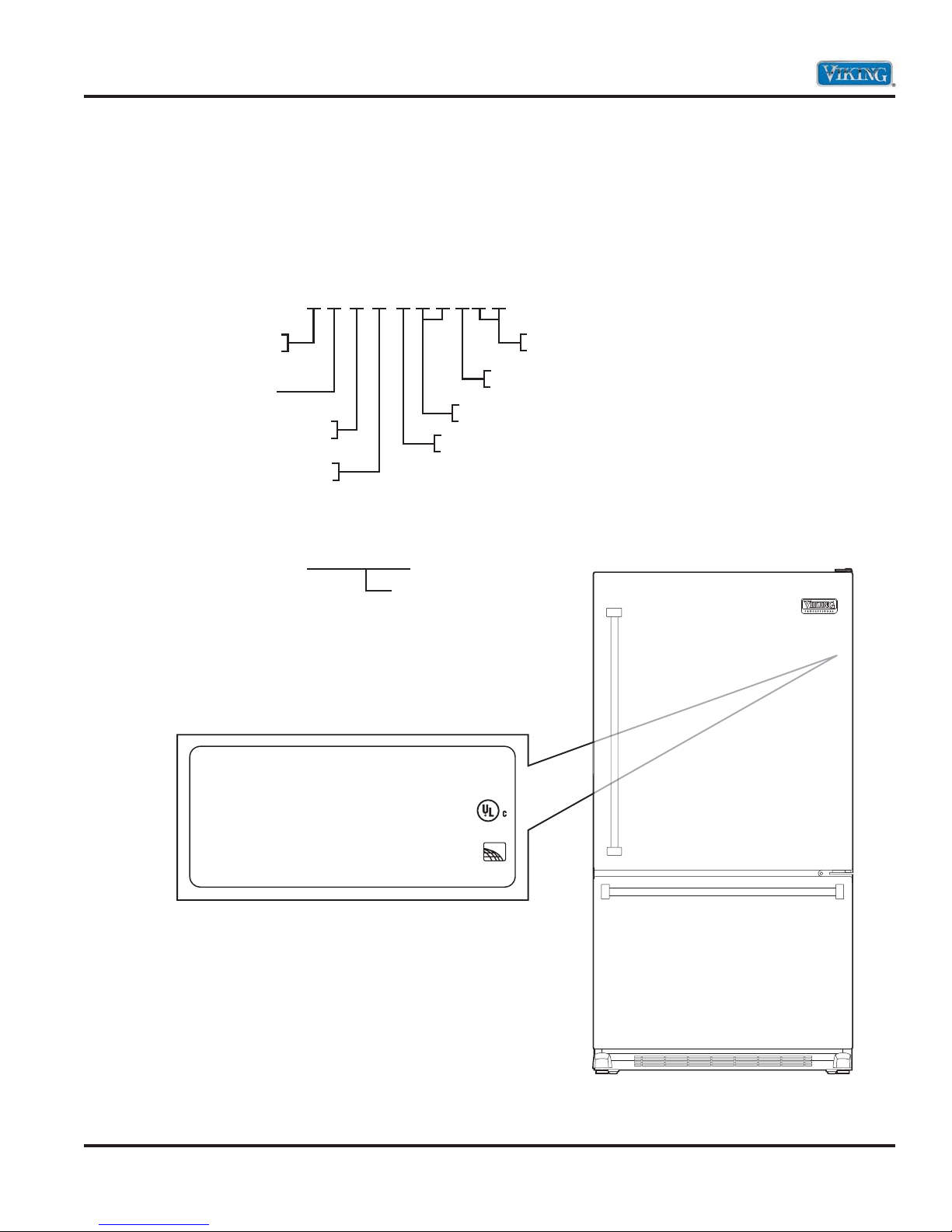
Model – Serial Number Matrix
The serial number and model number for your
appliance are located on the identifi cation plate
mounted on the upper right side of the door
opening.
Model Numbers
V=Professional Series
D=Designer Series
Commercial Door
B=Bottom-Mount
F=French Door
Serial Numbers
V C B F 136LSS
SS=Stainless
L=Left Hinge
R=Right Hinge
36” Wide
Version
Freestanding
KO2404122
Serial Number
VIKING RANGE CORP.
GREENWOOD MISSISSIPPI 36390
ASSEMBLED IN USA
MOD# VCBF136LSS3
SER# KO2404122
MINIMUM INSTALLATION CLEARANCE TOP-1/4 INCH
ESPACE DE DEGAGEMENT REQUIS-1/4
© 2011 Viking Preferred Service
5.00 oz R134a
148 g de R134a
115VAC/60Hz
7.90 A
CODE 10
LISTED HOUSEHOLD
REFRIGERATOR
1665
TYPE BMA200
ENERGY
PERFORMANCE
EEV109900
VERIFIED
6
Operation
Using the Controls
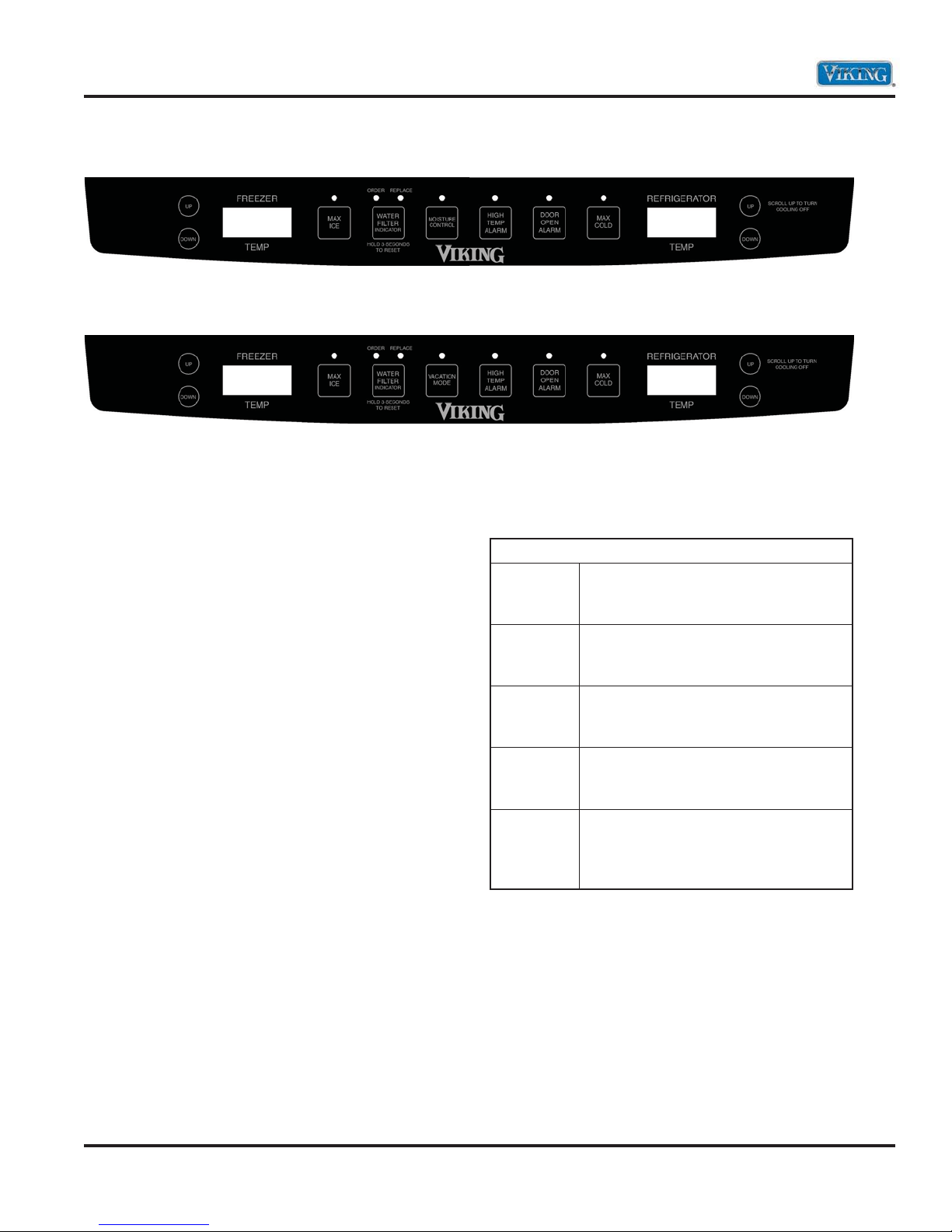
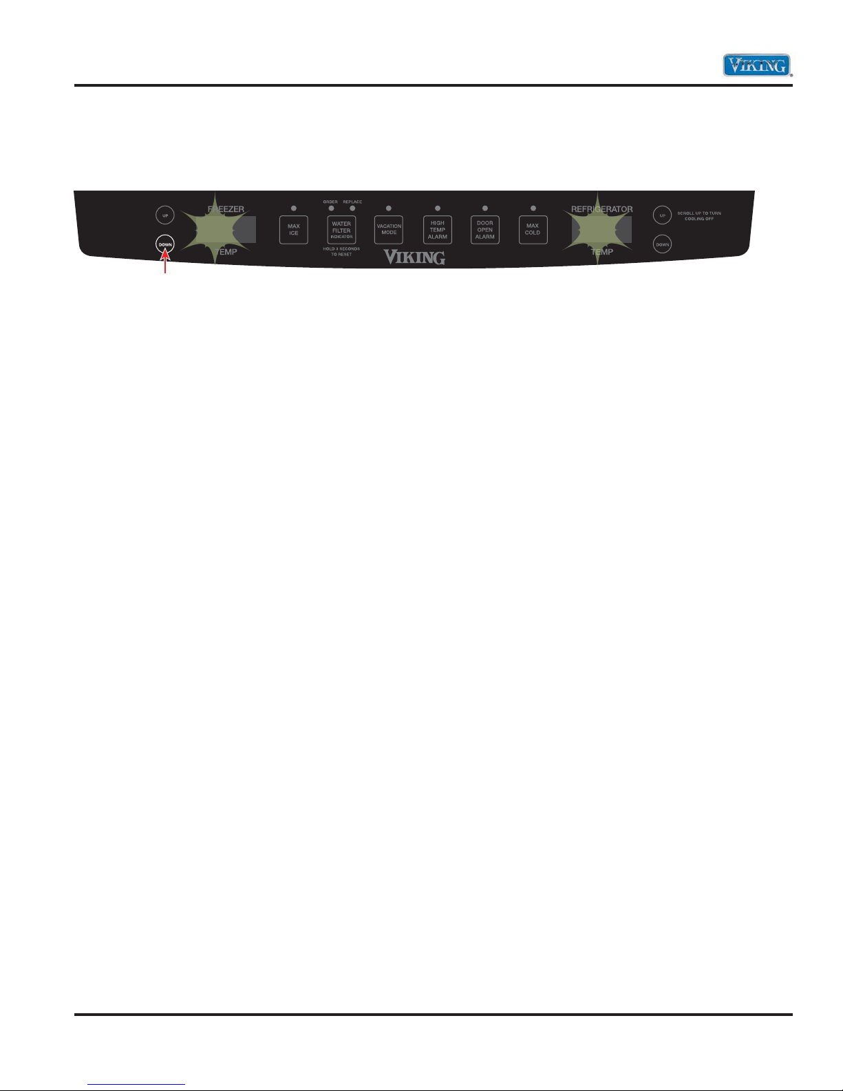
French Door Bottom-Mount control panel
Bottom-Mount control panel
Temperature Controls
Initial Temperature Setting
Temperatures are preset at the factory at 38°F
(3°C) in the refrigerator compartment and 0°F
(-18°C) in the freezer compartment.
Adjusting the Control
24 hours after adding food, you may decide that
one or both compartments should be colder or
warmer. If so, adjust the control as indicated in the
Temperature Control Guide below.
UÊÊÊÊ/iÊVÌÀÊ«>iÊÃÊV>Ìi`ÊÊÌiÊÃ`iÊvÊÌiÊ
refrigerator compartment at the top.
UКК К/iКwКАГМКМХVКvКМiК1*КАК"7 К«>`ГКГЬГК
the current temperature setting.
UÊÊ Ê/iÊ`ë>ÞÊÜÊÃÜÊÌiÊiÜÊÃiÌÌ}ÊvÀÊ
approximately three seconds, and then return
to the actual temperature currently within that
compartment.
UÊÊ DO NOT change either control more than one
degree at a time. Allow temperature to stabilize
for 24 hours before making a new temperature
adjustment.
IMPORTANT: Wait 24 hours for your refrigerator
to cool completely before adding food. If you add
food before the refrigerator has cooled completely,
your food may spoil.
Temperature Control Guide
Refrigerator
too cold
Set the refrigerator control to next
higher number by pressing the
“UP” pad.
Refrigerator
too warm
Set the refrigerator control to next
lower number by pressing the
“DOWN” pad.
Freezer
too cold
Freezer
too warm
Set the freezer control to next higher
number by pressing the “UP” pad.
Set the freezer control to next lower
number by pressing the “DOWN”
pad.
Turn
refrigerator
OFF
Press the freezer “UP” pad until OFF
appears in the display. Press either
the freezer or refrigerator “DOWN”
pad to turn back on.
UÊÊÊÊ/iÊÀiVi`i`ÊÃiÌÌ}ÃÊÃÕ`ÊLiÊVÀÀiVÌÊ
for normal household refrigerator use. The
controls are set correctly when milk or juice is as
cold as you like and when ice cream is fi rm.
UÊ ÊvÊÌiÊÌi«iÀ>ÌÕÀiÊÃÊÌÊÜ>ÀÊÀÊÌÊV`ÊÊ
the refrigerator or freezer, fi rst check the air
vents to be sure they are not blocked before
adjusting the controls.
© 2011 Viking Preferred Service
7
Operation
Adjusting Controls
The Fresh Food Temp control adjusts the
refrigerator compartment temperature. The Freezer
Temp control adjusts the freezer compartment
temperature.
If you need to adjust the temperature in either
the refrigerator or freezer compartment, use the
settings listed in the chart shown below as a guide.
Adjusting the Control
Twenty four hours after adding food, you may
decide that one or both compartments should
be colder or warmer. If so, adjust the control as
indicated in the Temperature Control Guide below.
UКК К/iКwАГМКМХVКvКМiК1*КАК"7 К«>`ГКГЬГК
the current temperature setting.
UÊÊ Ê/iÊ`ë>ÞÊÜÊÃÜÊÌiÊiÜÊÃiÌÌ}ÊvÀÊ
approximately three seconds, and then return
to the actual temperature currently within that
compartment.
UÊÊ ÊÊÌÊV>}iÊiÌiÀÊVÌÀÊÀiÊÌ>ÊiÊ
degree at a time. Allow temperature to stabilize
for 24 hours before making a new temperature
adjustment.
Options
Max Ice
When activated, Max Ice reduces the freezer
temperature to the optimum setting for 24 hours in
order to produce more ice.
Note: When the Max Ice feature is in operation, the
freezer UP and DOWN control pads will not operate.
Water Filter Indicator
When a water filter has been installed in the
refrigerator, the yellow order light will illuminate
when 90 percent of the volume of water for which
the filter is rated has passed through the filter.
The red replace light will illuminate when the rated
volume of water has passed through the filter.
A new filter should be installed immediately when
the replace light is illuminated. After replacing
the filter, press and hold the “WATER FILTER
INDICATOR” button for three seconds. The order
and replace lights will go off.
Vacation Mode
The Vacation Mode feature causes the freezer to
defrost less frequently, conserving energy. The
vacation mode indicator light will illuminate when
the feature is activated. To deactivate, press
the “VACATION MODE” pad again OR open either
door. The indicator light will go out.
Temperature Adjustment Chart
Condition/Reason Adjustment
Refrigerator too warm Fresh Food Control
1° lower
Freezer too warm/too
little ice
Refrigerator too cold Fresh Food Control
Freezer too cold Freezer Control
© 2011 Viking Preferred Service
Freezer Control
1° lower
1° higher
1° higher
Note: Door openings will not deactivate the
Vacation Mode for approximately one hour after
activation.
High Temp Alarm
The high temp alarm system will alert you if the
freezer or refrigerator temperatures exceed normal
operating temperatures due to a power outage
or other event. When activated, the high temp
alarm light will illuminate. If the freezer or
refrigerator temperatures have exceeded these
limits, the display will alternately show the current
compartment temperatures and the highest
compartment temperatures reached when the
power was out. An audible alarm will sound
repeatedly. Press the “HIGH TEMP ALARM”
pad once to stop the audible alarm. The high
temp alarm light will continue to flash and the
temperatures will alternate until the temperatures
have stabilized. To turn off High Temp Alarm, press
and hold the “HIGH TEMP ALARM” pad for three
seconds. The indicator light will go off.
8

Operation
Options (continued)
Moisture Control
The Moisture Control feature turns on a heater to
help reduce moisture on the door hinge seal.
Use in humid environments or when you notice
moisture on the door hinge seal. The refrigerator
uses more energy when moisture control is on.
Press “MOISTURE CONTROL” to turn the door
heater on. Press “MOISTURE CONTROl” again
to turn the heater off. The LED will be illuminated
when moisture control is on.
Door Open Alarm
The Door Open Alarm will alert you when one of
the doors has been left open for five continuous
minutes. When this happens, an audible alarm will
sound every few seconds until the door is closed
OR press the “DOOR OPEN ALARM” pad to
deactivate the feature.
Max Cold
When activated, Max Cold causes the refrigerator
and freezer temperatures to drop to the minimum
settings on the control. This cools down the
refrigerator and freezer after extended door
openings or when loading the refrigerator or
freezer with warm food.
To activate, press the “MAX COLD” pad. Max Cold
will deactivate automatically after 12 hours, OR
press the “MAX COLD” pad to deactivate the
feature.
Note: When the Max Cold feature is in operation,
the UP and DOWN pads for the refrigerator and
freezer controls will not operate.
User Settings
Access the User Preferences menu to:
UÊÊ >}iÊÌiÊÌi«iÀ>ÌÕÀiÊ`ë>ÞÊvÀÊcÊÌÊc
UÊÊ >LiÊÀÊ`Ã>LiÊ>Õ`LiÊ>>ÀÃ
UÊÊ VÌÛ>ÌiÊÌiÊ->LL>ÌÊ`i
To access the user preferences menu, press and
hold the “DOOR OPEN ALARM” pad for three
seconds. When in the user preferences mode, a
short title for the feature will appear in the feezer
temperature display and the feature status will
appear in the refrigerator display.
1. Use the freezer UP and DOWN control to scroll
through the features.
2. When the desired feature is displayed, use the
refrigerator UP and DOWN control to change
the status.
3. When changes are complete, press the “DOOR
OPEN ALARM” pad for three seconds OR close
the refrigerator door.
Temperature Display
Change the display to show temperatures in
degrees fahrenheit or degrees celsius.
Alarm (AL)
When the Alarm mode is off, all audible alarms will
be disabled until the feature is turned on.
Sabbath Mode (SAB)
When the Sabbath Mode is on, all control lights will
be disabled until the feature is turned OFF.
This feature does not disable the interior lights.
Press any pad to restore the control lights.
Moisture Adjustable Produce Drawer
You can control the amount of humidity in the
moisture adjustable produce drawer. Adjust
the control to any setting between LOW and
HIGH. LOW (open) for best storage of fruits and
vegetables with skins. HIGH (closed) for best
storage of fresh, leafy vegetables.
© 2011 Viking Preferred Service
MeatSavor™/Produce Drawer
The MeatSavor™ drawer is a full-width drawer with
adjustable temperature control. This drawer can be
used for large party trays, deli items, beverages or
miscellaneous items. There is a divider to organize
the drawer into sections if desired.
9

Operation
User Settings (continued)
MeatSavor Control
The control, located on the right of the drawer,
regulates the air temperature inside the drawer. Set
control to “COLD” to provide normal refrigerator
temperature. Use the “COLDEST” setting for meats
or other deli items.
UÊÊÊÊ`Ê>ÀÊ`ÀiVÌi`ÊÌÊÌiÊi>Ì->ÛÀÒÊV>Ê
decrease refrigerator temperature. Refrigerator
control may need to be adjusted.
UÊÊÊ DO NOT place leafy vegetables in the
MeatSavor™ drawer. Colder temperatures
could damage leafy produce.
To Remove:
UÊÊÊÊvÌÊ`°Ê*ÕÊ`À>ÜiÀÊÕÌÊÌÊvÕÊiÝÌiðÊ/ÌÊÌiÊ
drawer front up and pull straight out.
To Install:
UÊÊ Ê*ÕÃÊiÌ>Ê}`iÊÀ>ÃÊÌÊÌiÊL>VÊvÊÌiÊ
refrigerator. Place drawer onto rails and slide
drawer back until it falls into place.
To Remove Divider:
UÊÊÊÊ*ÕÊ`À>ÜiÀÊV«iÌiÞÊÕÌÊ>`ÊÀ>ÃiÊÌiÊvÀÌÊ
of the divider to unhook it from rear wall of the
drawer and lift it out.
To Install Divider:
UÊÊ ÊÊL>VÊvÊ`Û`iÀÊÛiÀÊÀi>ÀÊÜ>ÊvÊ`À>ÜiÀÊ
and lower into place.
Ice Maker and Ice Storage Bin
Alarm Sound
The ice maker and storage bin are located in the
the freezer compartment.
Turning the Ice Maker On/Off
The On/Off switch is located on the ice maker.
To turn ON the ice maker, press the switch to the
“ON” position.
To manually turn OFF the ice maker, press the
switch to the “OFF”position.
Note: Your ice maker has an automatic shutoff.
The ice maker sensors will automatically stop ice
production, but the control will remain in the
ON position.
Ice Production Rate
UКККККЬКУ{КХАГКМК«А`ХViКМiКwАГМКL>МVКvКVi°К
Discard the first three batches of ice produced.
UÊÊÊÊ/iÊViÊ>iÀÊÃÕ`Ê«À`ÕViÊ>««ÀÝ>ÌiÞÊnÊ
to 12 batches of ice in a 24 hour period.
UÊÊÊÊ/ÊVÀi>ÃiÊViÊ«À`ÕVÌ]ÊÜiÀÊÌiÊvÀiiâiÀÊ
and refrigerator temperature. See “Using the
Controls.” Wait 24 hours between adjustments.
Remember
UÊÊÊÊ/iʵÕ>ÌÞÊvÊÞÕÀÊViÊÜÊLiÊÞÊ>ÃÊ}`Ê
as the quality of the water supplied to the
ice maker. AVOID connecting the ice maker
to a softened water supply. Water softener
chemicals (such as salt) can damage parts of
the ice maker and lead to poor quality ice. If a
softened water supply cannot be avoided, make
sure the water softener is operating properly
and is well maintained.
UÊÊ DO NOT use anything sharp to break up the ice
in the bin. This can cause damage to the ice bin
and dispenser mechanism.
UÊÊ Ê DO NOT store anything on top of the ice maker
or in the ice storage bin.
© 2011 Viking Preferred Service
10

Operation
Water Filtration System
The water filter is located in the upper right-hand
corner of the refrigerator compartment.
Note: DO NOT use with water that is
microbiologically unsafe or of unknown quality
without adequate disinfection before or after the
system. Systems certified for cyst reduction may
be used on disinfected waters that may contain
filterable cysts.
Replacing the Water Filter
Replacement water filters are available through
your local Viking Range Dealer. You may also order
filters by calling 1-888-845-4641 or online at
vikingrange.com
IMPORTANT: Air trapped in the water system may
cause water and filter to eject. Always dispense
water for at least 2 minutes before removing the
filter or blue bypass cap.
1. Turn filter counterclockwise to remove.
2. Remove sealing label from replacement filter
and insert the filter end into the filter head.
3. Turn the filter clockwise until it stops. Snap the
filter cover closed.
Note: The dispenser feature may be used without a
water filter installed. Your water will not be filtered.
If this option is chosen, replace the filter with the
blue bypass cap.
Refrigerator Water Filter
Cartridge Model RWFFR
Specifications:
Service Flow Rate (Maximum) ................... 0.78 GPM
...................................................................(2.9 L/min)
Rated Service Life ...........................................RWFFR
(750 gal. Max) ............................. 750 gal./2838 liters
Maximum Operating Temperature ........ 100°F/38°C
Minimum Pressure Requirement .......35 psi/241 kPA
Minimum Operating Temperature ............. 33°F/1°C
Maximum Operating Pressure ........ 120 psi/827 kPA
Cleaning
WARNING
EXPLOSION HAZARD
Use nonflammable cleaner.
Failure to do so can result in death, explosion,
or fire.
Both the refrigerator and freezer sections defrost
automatically. However, clean both sections about
once a month to avoid buildup of odors. Wipe
up spills immediately.
IMPORTANT: Because air circulates between both
sections, any odors formed in one section will
transfer to the other. You must thoroughly
clean both sections to eliminate odors. To avoid
odor transfer and drying out of food, wrap or cover
foods tightly.
To Clean Your Refrigerator:
Note: DO NOT use abrasive or harsh cleaners such
as window sprays, scouring cleansers, flammable
fluids, cleaning waxes, concentrated detergents,
bleaches or cleansers containing petroleum
products on plastic parts, interior and door liners or
gaskets. DO NOT use paper towels, scouring pads,
or other harsh cleaning tools.
1. Unplug refrigerator or disconnect power.
2. Hand wash, rinse, and dry removable parts and
interior surfaces thoroughly. Use a clean sponge
or soft cloth and a mild detergent in warm water.
3. Wash stainless steel and painted metal exteriors
with a clean sponge or soft cloth and a mild
detergent in warm water.
4. There is no need for routine condenser cleaning
in normal home operating environments. If
the environment is particularly greasy or dusty,
or there is significant pet traffic in the home,
the condenser should be cleaned every 2 to 3
months to ensure maximum efficiency.
If you need to clean the condenser:
Ê UÊ ,iÛiÊÌiÊL>ÃiÊ}Ài°
Ê UÊÊÊÊ1ÃiÊ>ÊÛ>VÕÕÊVi>iÀÊÜÌÊ>ÊÃvÌÊLÀÕÃÊ
to clean the grille, the open areas behind
the grille and the front surface area of the
condenser.
Ê UККККККК,i«>ViКМiКL>ГiК}АiКЬiКwГi`°
© 2011 Viking Preferred Service
5. Plug in refrigerator or reconnect power.
11
Diagnostics
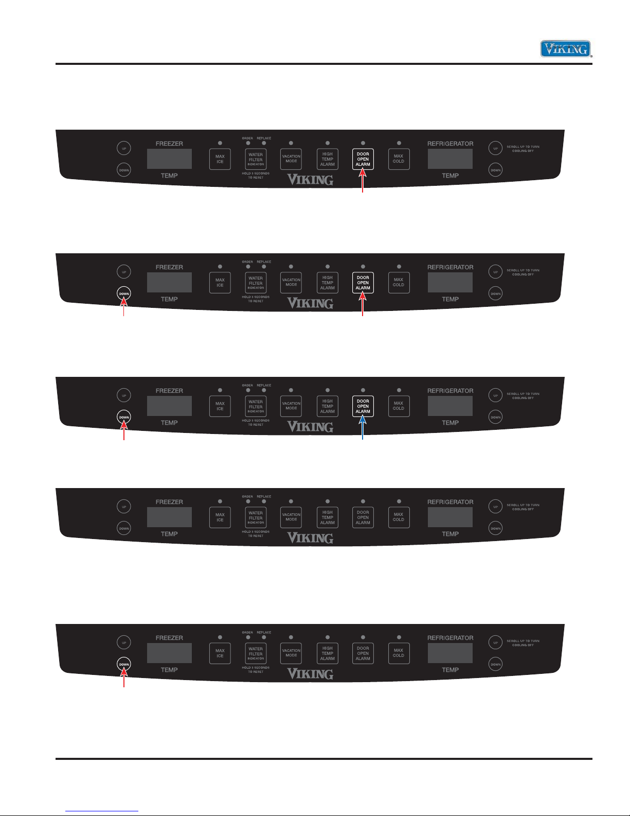
Entering Programming Mode
1. Press and hold the “Door Alarm” keypad.
Press and Hold
2. Within three seconds, press and hold freezer temperature “DOWN” keypad. Both keypads are now
being held in.
HoldPress and Hold
3. While still holding the freezer temperature “DOWN”, release the “DOOR ALARM” keypad and wait
three seconds.
ReleaseHold
4. When entered successfully, the freezer temperature screen will display PE.
PE
5. Entry is confirmed by pressing the freezer temperature “DOWN” keypad. The refrigerator temperature
screen will display a three digit number. These three numbers are the current programming code for this
unit. The example below shows code 010.
PE 010.
Press
Note: There is a decimal to the right of the last number. This will be explained later.
© 2011 Viking Preferred Service
12
Diagnostics
Entering Programming (continued)
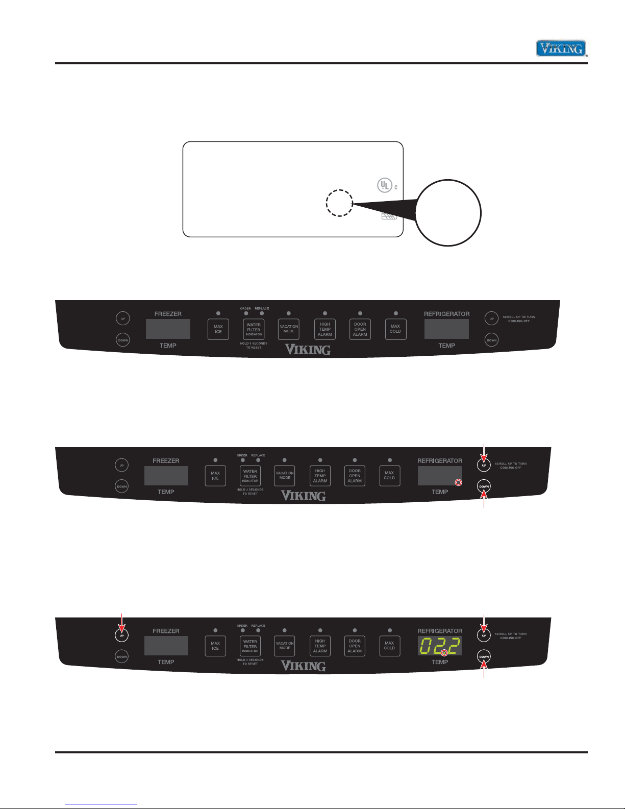
6. This code can be verified with the Program CODE printed on the unit serial plate as shown in the example
below. The code in the display and the code on the data plate match.
VIKING RANGE CORP.
GREENWOOD MISSISSIPPI 36390
ASSEMBLED IN USA
MOD# VCBF136LSS3
SER# KO2404122
MINIMUM INSTALLATION CLEARANCE TOP-1/4 INCH
ESPACE DE DEGAGEMENT REQUIS-1/4
5.00 oz R134a
148 g de R134a
115VAC/60Hz
7.90 A
CODE 10
LISTED HOUSEHOLD
REFRIGERATOR
1665
TYPE BMA200
ENERGY
PERFORMANCE
EEV109900
VERIFIED
10
7. If the code does NOT match, you must enter the proper code into the controller. Below is an example of an
improperly programmed controller. The code is showing 022 which does not match the data plate above.
PE 022.
Incorrect code shown above
8. As mentioned before, the first digit has a decimal beside it. This indicates that the First digit is in
programming mode. Using either the refrigerator temperature UP or DOWN keypads, this digit can be
changed from 0-9.
PE 022.
Press either button to scroll through
the numbers until the proper number
is in the display
9. Press the freezer temperature “UP” keypad to select the next digit. Using either the refrigerator
temperature UP or DOWN keypads, change the second digit. Repeat this process for the
third digit.
Press
PE
Press either button to scroll through
the numbers until the proper number
© 2011 Viking Preferred Service
13
Diagnostics
Entering Programming Mode (continued)
10. Once the desired program code is entered, press and hold the freezer temperature “DOWN” keypad
until the program code begins fl ashing indicating it has been saved.
PE 010.
Note: If you attempt to enter an invalid program code, the control will not save the new code, but will
beep. (The unit will NOT run with a program code of 0000). Once the program code has been saved, the
Programming Mode is exited by pressing any key. If the new code is incorrect, this process should be
repeated.
Note: The Programming Mode can be exited at any time by pressing “DOOR ALARM” key for three seconds
or will exit if unattended for four minutes.
© 2011 Viking Preferred Service
14
Diagnostics
Defrost Operation
The Control Board adapts the compressor run time between defrosts to achieve optimum defrost intervals
by monitoring the length of time the defrost heater is on. After initial power up, defrost interval is 4 hours
compressor run time. Defrost occurs immediately after the 4 hours of compressor run time.
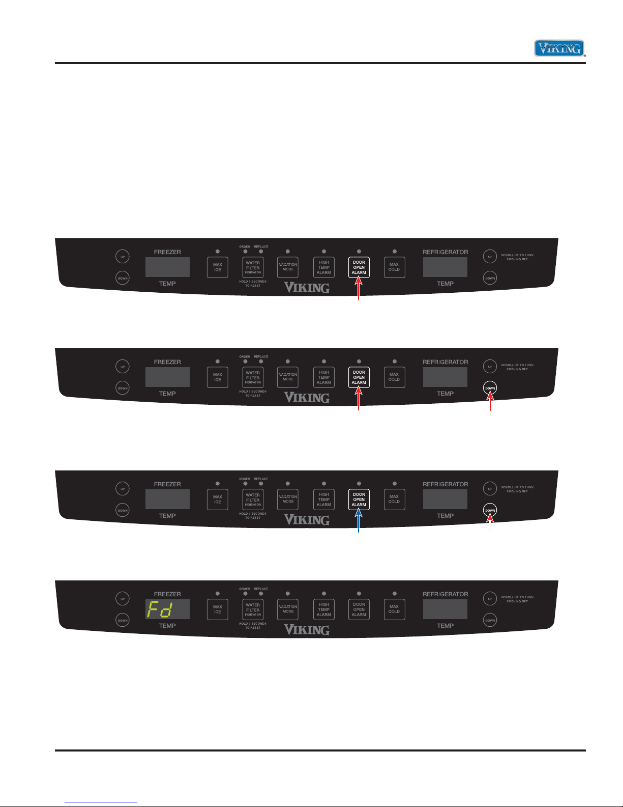
Entering Forced Defrost Mode
Enter the Forced Defrost Mode by performing the following:
1. Press and hold the “DOOR ALARM” keypad.
Press and Hold
2. Then press and hold refrigerator temperature “DOWN” keypad. Both buttons are now being held in.
Hold Press and Hold
3. While still holding the refrigerator temperature “DOWN” keypad, release the door alarm keypad and wait
three seconds.
HoldRelease
4. When entered successfully, Fd will be displayed in freezer display.
© 2011 Viking Preferred Service
15
Diagnostics
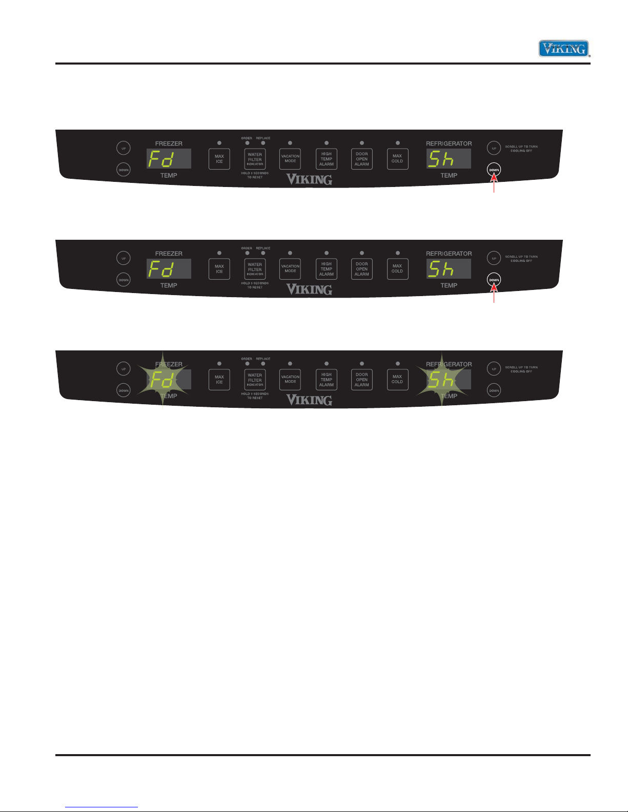
Entering Forced Defrost Mode (continued)
5. Press the refrigerator temperature “DOWN” keypad again. Sh appears in right display.
6. Press refrigerator temperature “DOWN” keypad again to force defrost .
7. Fd and Sh will fl ash in display indicating unit is in defrost.
Press
Press
© 2011 Viking Preferred Service
16

Diagnostics
Entering Service Test Mode
1. Press and hold the “DOOR ALARM” keypad.
Press and Hold
2. Within three seconds, press and hold refrigerator temperature “UP” keypad. Both keypads are now
being held in.
Hold
3. While still holding the refrigerator temperature “UP”, release the “DOOR ALARM” keypad and wait three
seconds.
Press and Hold
Press and Hold
Release
4. When entered successfully, the freezer temperature screen will display SE.
SE
5. Entry is confirmed by pressing the refrigerator temperature “UP” keypad. Freezer temperature screen will
display 101. Refrigerator screen will display OFF.
Press
101 OFF
7. To exit Service Test Mode, open and close refrigerator door(s) or hold door alarm for 3 seconds.
© 2011 Viking Preferred Service
17
 Loading...