

Viking DDFB304 Installation Manual
Viking Installation Guide
U
L
C
U
L
Viking Range Corporation
111 Front Street
Greenwood, Mississippi 38930 USA
(662) 455-1200
For product information,
call 1-888-VIKING1 (845-4641)
or visit the Viking Web site at
vikingrange.com
All Refrigerator/Freezer
F20416D EN
(071508J)
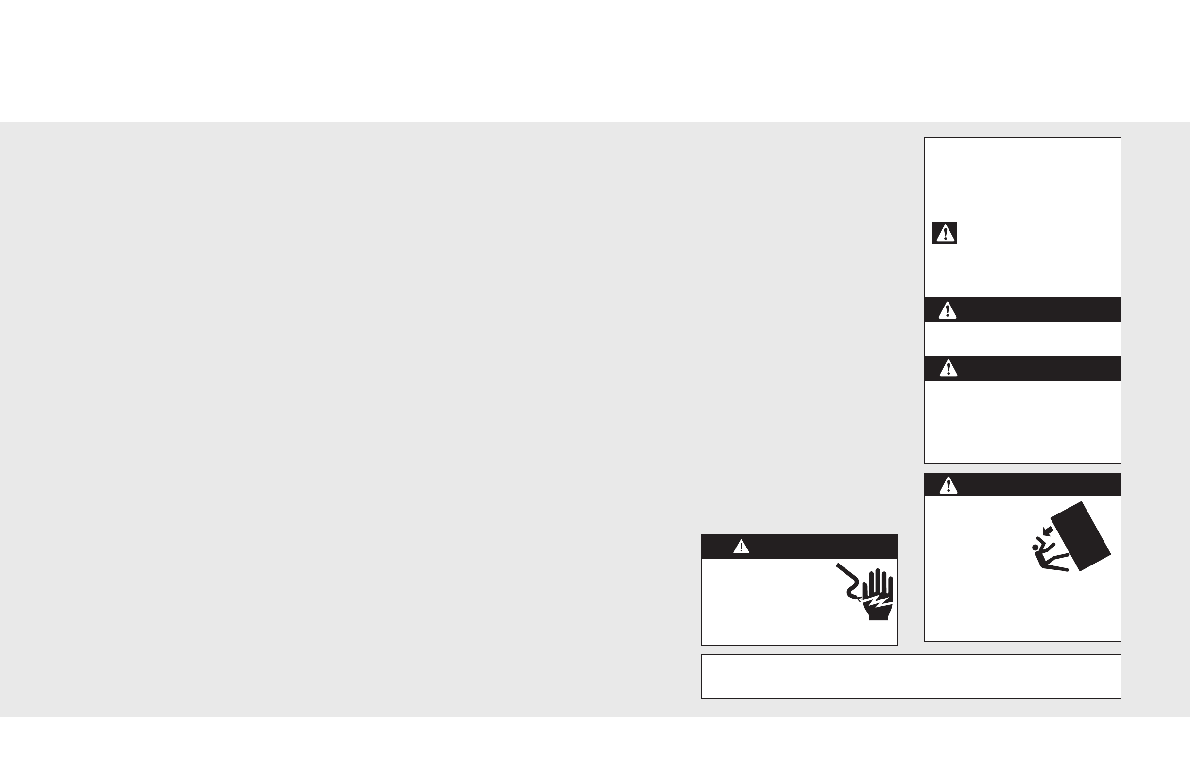
Table of Contents IMPORTANT–Please Read and Follow!
Make sure that incoming voltage is the same
Warnings & Important Information
Professional & Professional Integrated
Dimensions & Specifications (30” & 36” Professional) _______________________________ 4
Dimensions & Specifications (30” & 36” Professional Integrated) _____________________ 6
Cutout Dimensions (30” Professional & Professional Integrated) ______________________ 8
Anti-Tip Dimensions (30” Professional & Professional Integrated) _____________________ 9
Cutout Dimensions (36” Professional & Professional Integrated) _____________________ 10
Anti-Tip Dimensions (36” Professional & Professional Integrated) _____________________ 11
Dimensions & Specifications (Dual Professional) ____________________________________ 12
Dimensions & Specifications (Dual Professional Integrated) ___________________________16
Cutout Dimensions (Dual 30” Professional & Professional Integrated) _________________ 20
Anti-Tip Dimensions (Dual 30” Professional & Professional Integrated) ________________ 21
Cutout Dimensions (Dual 30” & 36” Professional & Professional Integrated) ___________ 22
Anti-Tip Dimensions (Dual 30” & 36” Professional & Professional Integrated) __________ 23
Cutout Dimensions (Dual 36” Professional & Professional Integrated) _________________ 24
Anti-Tip Dimensions (Dual 36” Professional & Professional Integrated) _________________25
Cabinet Information (Professional) ________________________________________________ 26
Cabinet Information (Professional Integrated) ______________________________________ 28
Designer
Dimensions & Specifications (30”& 36”) ___________________________________________ 30
Cutout Dimensions (30”)_________________________________________________________ 32
Anti-Tip (30”)___________________________________________________________________ 33
Cutout Dimensions (36”)_________________________________________________________ 34
Anti-Tip Dimensions (36”)________________________________________________________ 35
Dimensions & Specifications (Dual)________________________________________________ 36
Cutout Dimensions (Dual 30”) ____________________________________________________ 40
Anti-Tip Dimensions (Dual 30”) ___________________________________________________ 41
Cutout Dimensions (Dual 30” & 36”) ______________________________________________ 42
Anti-Tip Dimensions (Dual 30” & 36”) _____________________________________________ 43
Cutout Dimensions (Dual 36”) ____________________________________________________ 44
Anti-Tip Dimensions (Dual 36”) ___________________________________________________ 45
Cabinet Information_____________________________________________________________ 46
Custom Side Panel Dimensions (Professional) __________________________________________ 48
Custom Side Panel Dimensions (Designer & Professional Integrated) _____________________ 49
General Information ________________________________________________________________ 50
Unpacking & Moving ____________________________________________________________ 52
Installation_________________________________________________________________________ 53
Hinge Adjustment ______________________________________________________________ 54
Kickplate Installation ____________________________________________________________ 56
Door Stop Adjustment __________________________________________________________ 57
Final Installation ________________________________________________________________ 57
Performance Checklist ______________________________________________________________ 59
Control Panels _____________________________________________________________________ 60
Service & Registration_______________________________________________________________ 61
_________________________________________________________
3
•
as unit rating. An electric rating plate
specifying voltage, frequency, wattage,
amperage, and phase is attached to the
product.
• To reduce the risk of fire, electric shock, or
injury to persons, installation work and
electrical wiring must be done by qualified
people in accordance with all applicable
codes and standards, including fire-rated
construction.
• The installer should leave these instructions
with the consumer who should retain them
for local inspector’s use and for future
reference.
It is your responsibility to:
• comply with installation specifications and
dimensions.
• properly install unit.
• remove any moldings or decorative panels
that prevent the unit from being serviced.
• make sure that you have these materials (not
provided with your unit), which are necessary
for proper installation:
• 1/4” (6 mm) copper tubing with shutoff
valve
• 6– #8 x 3” (7.6 cm) wood screws (longer
screws may be required)
• 1– Saddle valve (do not use self-piercing
feature of the valve)
• assure that floor will support unit, door
panels and contents (approximately 1200
pounds [540 kg]).
• provide a properly grounded electrical outlet.
• assure that location will permit appliance
doors to open 90˚ minimum.
W A R N I N G
ELECTRICAL SHOCK
HAZARD
Disconnect power or turn
power disconnect switch to
OFF position before removing
top grille. Failure to do so can
result in death or electrical shock.
Your safety and the safety of others is
very important.
We have provided many important safety
messages in this manual and on your
appliance. Always read and obey all
safety messages.
This is the safety alert symbol. This
symbol alerts you to hazards that
can kill or hurt you and others.
All safety messages will be preceded by the
safety alert symbol and the word“DANGER”
or “WARNING.”These words mean:
D A N G E R
You will be killed or seriously injured if
you don’t follow instructions.
W A R N I N G
You can be killed or seriously injured if
you don’t follow instructions.
All safety messages will identify the
hazard, tell you how to reduce the chance
of injury, and tell you what can happen if
the instructions are not followed.
W A R N I N G
TIP OVER HAZARD
Appliance is top
heavy and tips easily
when not completely
installed. Keep doors
closed until appliance
is completely installed
and secured per installation instructions.
Use two or more people to move and
install appliance. Failure to do so can
result in death or serious injury.
Most of the unit’s weight is at the top. Extra care is needed when moving the unit to prevent
tipping. Use cardboard shipping material or plywood under unit until it is installed in the
operating position to protect floor surface.
2
3

24–1
1
/1
6
”
(62
.
7
cm)
35”
(
8
8
.
9
cm)
75–
15/
16”
(
1
9
2
.9
cm
)
3–1
9
/
32
”
(
9
.1
cm
)
)
36
”
(
91
.
5
cm)
27
–
1/4”
(
69
.2 c
m)
9
–5
/
32
”
(
23
.
3
c
m)
82
–
3
/4
”
(21
0
.2
cm
)
m
in
.
to
8
4
–
1/1
6”
(21
3
.
5
cm
)
m
ax
.
20–
3/4
”
(52
.7
c
m)
22
–3/1
6”
(5
6
.4
c
m
)
24–1
1/16
”
(62
.7
cm
)
29”
(
7
3
.
7
c
m
)
7
5
–
1
5
/
1
6
”
(
19
2.
9
cm
)
3
–1
9
/32”
(
9
.
1
c
m
)
3
0
”
(
7
6
.
2
cm)
9
–
5
/
3
2
”
(
2
3
.3
cm
)
82
–
3
/4
”
(21
0
.2
c
m)
min
.
to
8
4
–
1/1
6
”
(21
3
.5
c
m
)
max
.
20–
3/4
”
(52
.7
c
m)
2
2
–3/
1
6”
(56
.4
c
m)
27
–
1
/4
”
(69
.2
c
m)
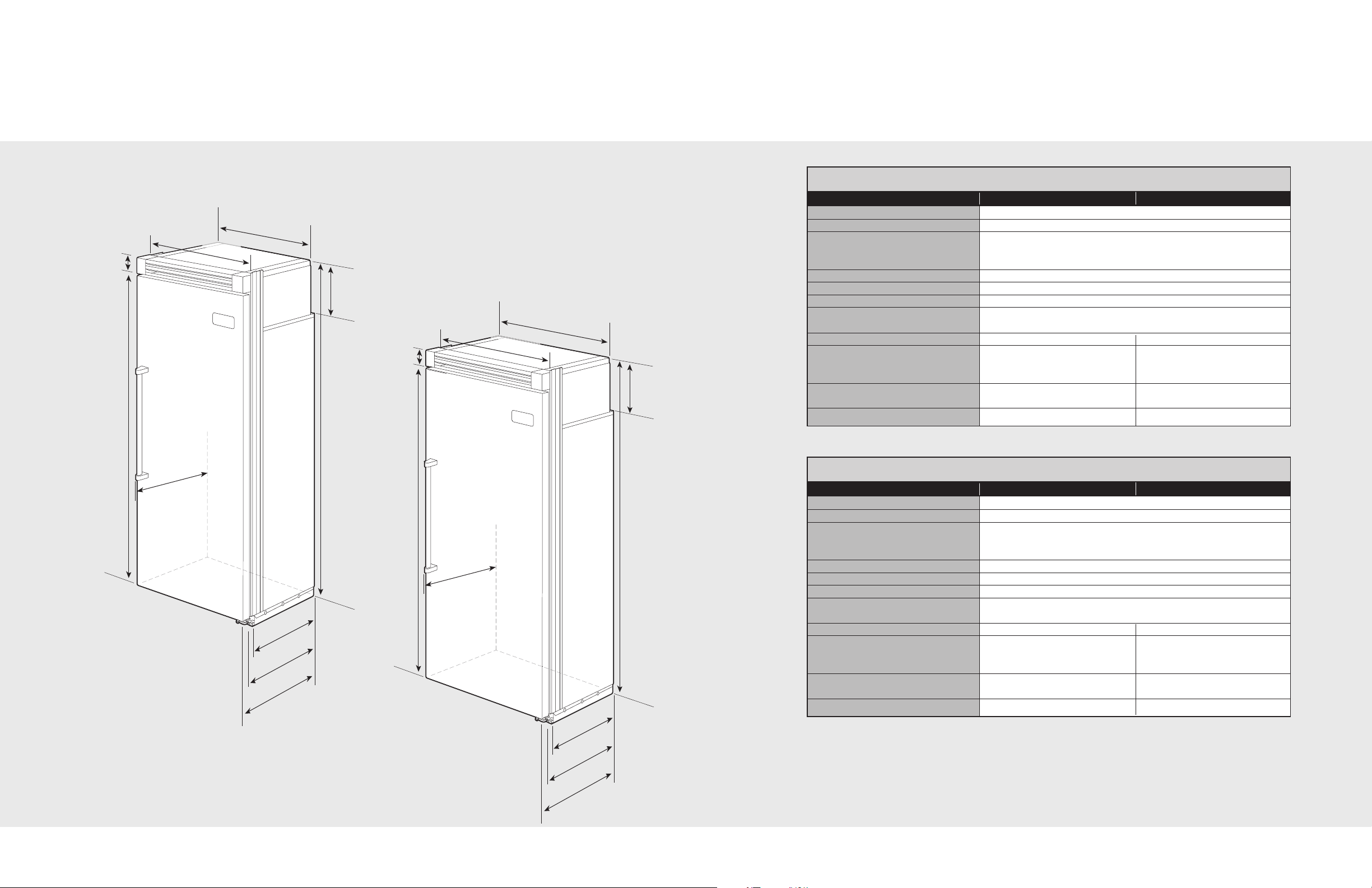
Dimensions
Specifications
30” Professional
30” Professional
Description VCFB304 VCRB304
Overall width 30” (76.2 cm)
Overall height from bottom 82-3/4” (210.2 cm) min. to 84-1/16” (213.5 cm) max.
Overall depth from rear To front edge of side trim: 22-3/16” (56.4 cm)
To front of top grille: 24-11/16” (62.7 cm)
36” Professional
Cutout width 29-1/2” (74.9 cm) min. to 29-3/4” (75.6 cm) max.
Cutout height 82-7/8” (210.5 cm) min. to 84-1/16” (213.5 cm) max.
Cutout depth 24” (61.0 cm) min.
Electrical requirements 115 volt, 60 Hz, 15 amp dedicated circuit; 3-wire cord with
Maximum amp usage 9.1 amps 5.7 amps
Inlet water requirements 1/4” copper tubing inlet
Overall interior dimensions
Total capacity 15.9 cu. ft. (450 liters) 18.2 cu. ft. (516 liters)
Approximate shipping weight 530 lbs. (238.5 kg) 505 lbs. (227.3 kg)
To front of handle endcap: 27-1/4” (69.2 cm))
grounded 3-prong plug attached to product
waterline; minimum 20 psi; N/A
maximum 120 psi
36” Professional
4
Description VCFB364 VCRB364
Overall width 36” (91.5 cm)
Overall height from bottom 82-3/4” (210.2 cm) min. to 84-1/16” (213.5 cm) max.
Overall depth from rear To front edge of side trim: 22-3/16” (56.4 cm)
To front of top grille: 24-11/16” (62.7 cm)
To front of handle endcap: 27-1/4” (69.2 cm)
Cutout width 35-1/2” (90.2 cm) min. to 35-3/4” (90.8 cm) max.
Cutout height 82-7/8” (210.5 cm) min. to 84-1/16” (213.5 cm) max.
Cutout depth 24” (61.0 cm) min.
Electrical requirements 115 volt, 60 Hz, 15 amp dedicated circuit; 3-wire cord with
grounded 3-prong plug attached to product
Maximum amp usage 9.5 amps 6.5 amps
Inlet water requirements 1/4” copper tubing inlet
waterline; minimum 20 psi; N/A
maximum 120 psi
Overall interior dimensions
Total capacity 19.1 cu. ft. (541 liters) 22.8 cu. ft. (646 liters)
Approximate shipping weight 585 lbs. (263.3 kg) 570 lbs. (256.5 kg)
5
2
4
”
(61
.0
cm)
35”
(88
.9
c
m)
75–
15/
16”
(
1
9
2
.9
c
m
)
3
–19
/3
2
”
(
9
.
1
c
m
)
)
3
6
”
(91
.5
c
m
)
26–
1/2”
(
67
.3
c
m)
9–5
/32
”
(
23
.
3
cm)
82
–
3/4”
(
21
0
.
2
c
m)
m
i
n
.
t
o
84–
1
/
1
6
”
(
21
3.
5
cm
)
m
ax
.
20–
3
/
4
”
(52
.7
c
m)
23–
3
/
8
”
(59
.4
cm
)
24”
(61
.0
c
m
)
2
9
”
(
7
3
.
7
c
m
)
7
5
–
1
5
/
16”
(
1
9
2.
9
c
m
)
3–
19
/3
2
”
(
9
.1
cm
)
3
0
”
(76
.2
c
m
)
9–5
/32
”
(
23
.
3
c
m)
82
–
3/
4”
(
21
0
.
2
c
m
)
m
i
n
.
t
o
84–
1
/
1
6”
(
21
3
.
5
cm
)
max
.
20–
3/4
”
(52
.7 c
m)
23
–
3/
8”
(59
.4
cm)
26–
1/2”
(
67
.3 c
m)
Dimensions
Specifications
30” Professional Integrated
30” Professional Integrated
Description VIFB304 VIRB304
verall width 30” (76.2 cm)
O
Overall height from bottom 82-3/4” (210.2 cm) min. to 84-1/16” (213.5 cm) max.
Overall depth from rear To front edge of side trim: 23-3/8” (59.4 cm)
To front of top grille: 24” (61.0 cm)
To front of handle endcap: 26-1/2” (67.3 cm)
36” Professional Integrated
Cutout width 30” (74.9 cm)
Cutout height 82-7/8” (210.5 cm) min. to 84-1/16” (213.5 cm) max.
Cutout depth 24” (61.0 cm) min.
Electrical requirements 115 volt, 60 Hz, 15 amp dedicated circuit; 3-wire cord with
grounded 3-prong plug attached to product
Maximum amp usage 9.1 amps 5.7 amps
Inlet water requirements 1/4” copper tubing inlet
waterline; minimum 20 psi; N/A
maximum 120 psi
Overall interior dimensions
Total capacity 15.9 cu. ft. (450 liters) 18.2 cu. ft. (516 liters)
Approximate shipping weight 530 lbs. (238.5 kg) 505 lbs. (227.3 kg)
36” Professional Integrated
6
Description VIFB364 VIRB364
Overall width 36” (91.5 cm)
Overall height from bottom 82-3/4” (210.2 cm) min. to 84-1/16” (213.5 cm) max.
Overall depth from rear To front edge of side trim: 23-3/8” (59.4 cm)
To front of top grille: 24” (61.0 cm)
To front of handle endcap: 26-1/2” (67.3 cm)
Cutout width 36” (91.4 cm)
Cutout height 82-7/8” (210.5 cm) min. to 84-1/16” (213.5 cm) max.
Cutout depth 24” (61.0 cm) min.
Electrical requirements 115 volt, 60 Hz, 15 amp dedicated circuit; 3-wire cord with
grounded 3-prong plug attached to product
Maximum amp usage 9.5 amps 6.5 amps
Inlet water requirements 1/4” copper tubing inlet
waterline; minimum 20 psi; N/A
maximum 120 psi
Overall interior dimensions
Total capacity 19.1 cu. ft. (541 liters) 22.8 cu. ft. (646 liters)
Approximate shipping weight 585 lbs. (263.3 kg) 570 lbs. (256.5 kg)
7
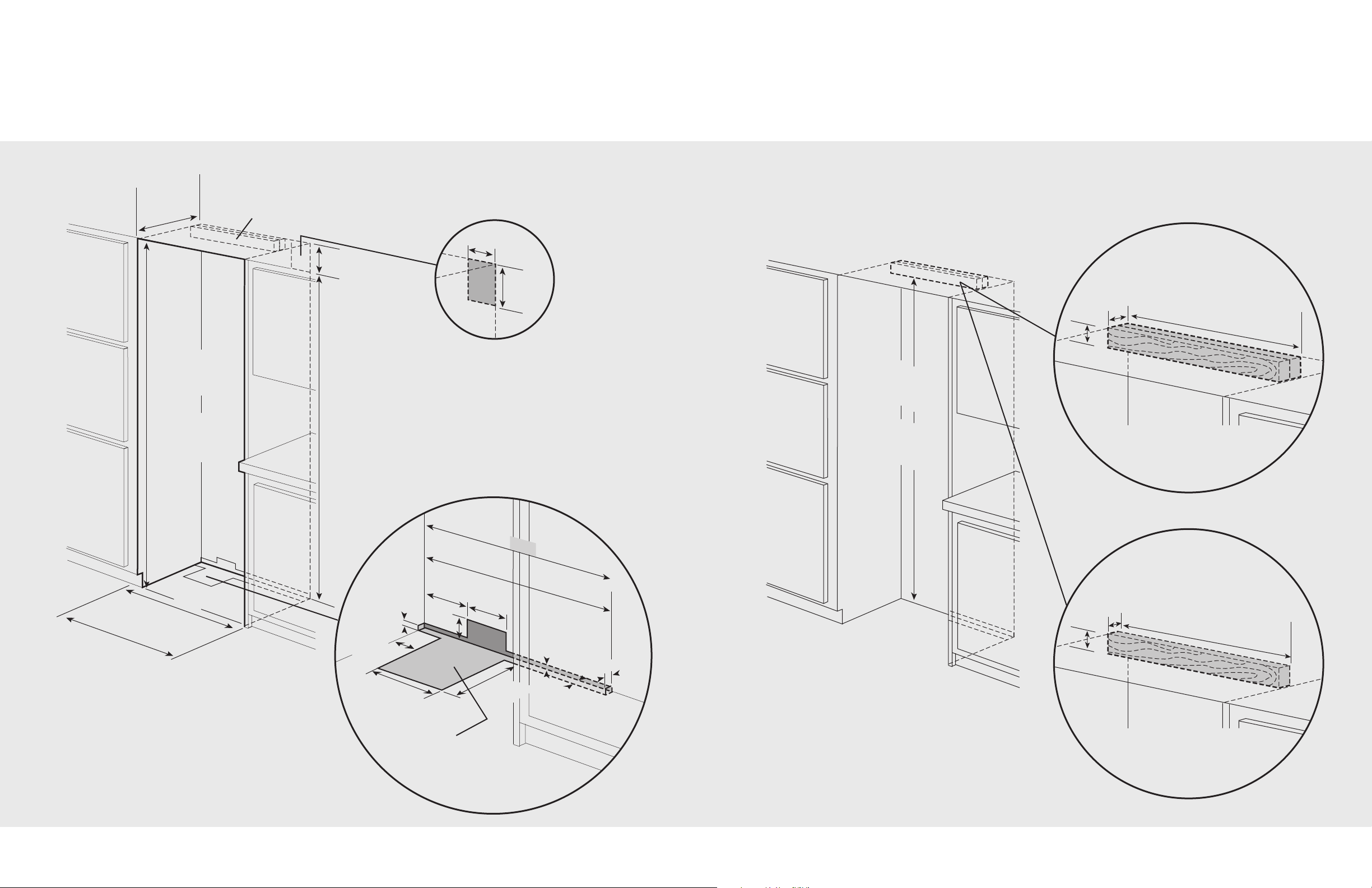
Bottom of anti-tip board is 3–7/8” (9.8 cm) below opening height.
Note: Top of unit must be placed firmly under anti-tip board.
Professional Anti-Tip Location
Professional Integrated Anti-Tip Location
NOTE: If unit is installed deeper than
24” (61.0 cm),then shim behind the mounting
board by the difference.
NOTE: If unit is installed deeper than
24” (61.0 cm), then shim behind the mounting
board by the difference.
Two 2”x 4” mounting boards
3” (7.6 cm) x 3-1/2” (8.9 cm)
One 2”x 4” mounting board
1–1/2” (3.8 cm) x 3-1/2” (8.9 cm)
7
9–
3/8”
(2
0
1
.6
c
m)
mi
n.
t
o b
ot
t
o
m
of
a
nti
-
t
i
p
b
o
a
rd
8
0–
1/2”
(20
4.6
c
m)
ma
x.
t
o b
ot
t
o
m
of
a
nti
-
t
i
p
b
o
a
rd
23”
(58
.4
c
m)
3–
1/
2
”
(
8
.
9
c
m
)
3
”
(
7
.
6
c
m
)
2
3
”
(5
8
.4
c
m
)
3–
1/
2
”
(8
.9
cm
)
1–1
/2
”
(3.
8 c
m)
9”
(
22
.
9
c
m
)
73–
3/
8”
(18
6.4
c
m)
8
2–
7/8”
(2
1
0
.5
c
m)
mi
n
.
a
n
t
i
-
t
ip
b
o
ar
d
&
o
p
en
ing
he
igh
t
84–1
/16
”
(
2
1
3
.
5
c
m)
mi
n
.
an
t
i-t
ip
boa
r
d
&
ope
n
in
g h
e
ig
h
t
2
9–1
/2”
(
74
.9
cm)
m
i
n.
t
o
29
-
3
/
4
”
(7
5
.6
c
m
)
ma
x
.
30
”
(7
6.2
cm
)
Pro
fes
sio
n
a
l
I
n
teg
rat
ed
Mod
els
O
n
l
y
2
4”
(61
.0 c
m
)
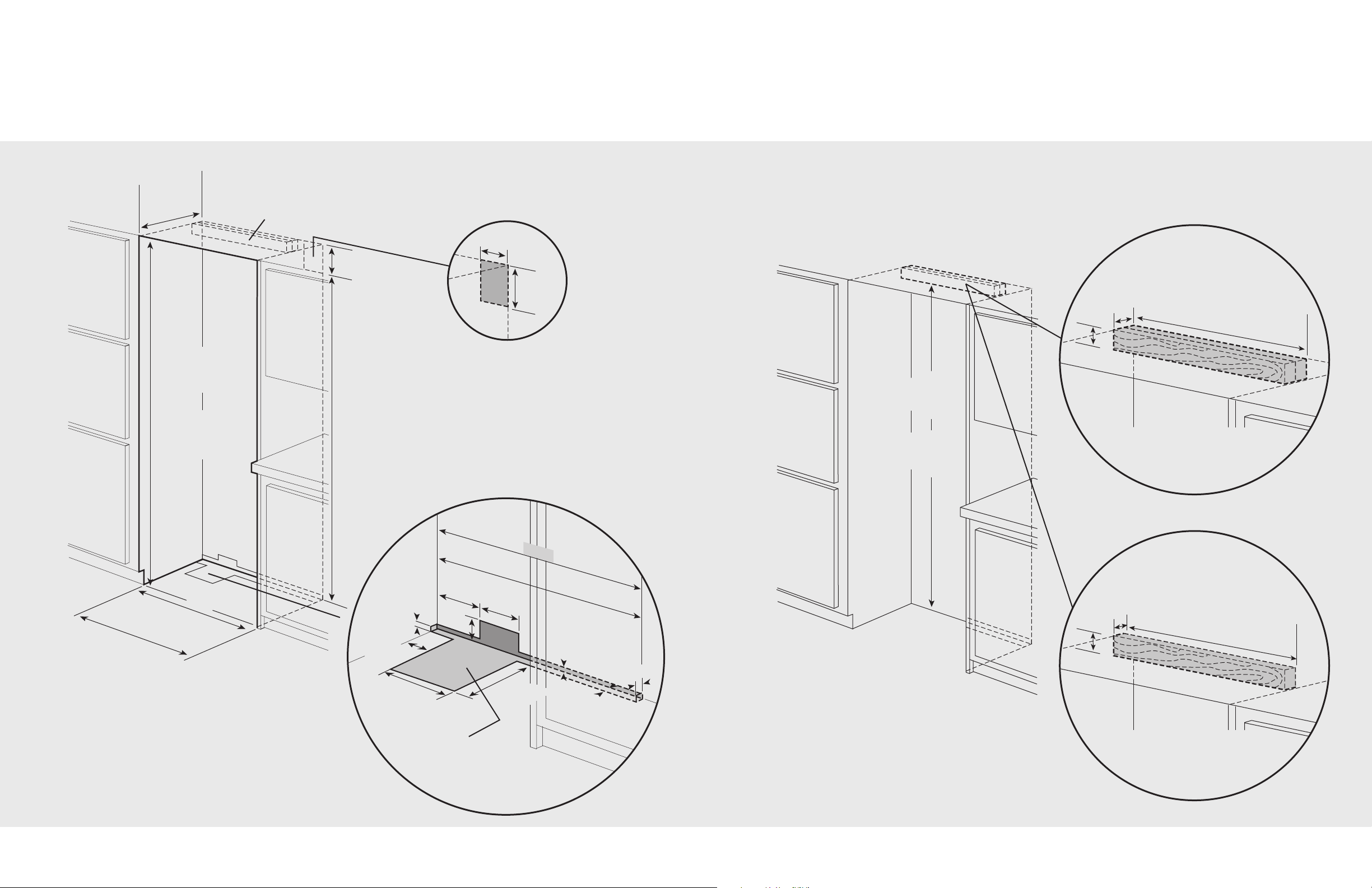
Electric Outlet Location
Water Line Entry Area
Note: Shown for All Freezer Only
29–1/
2”
(
7
4
.9
c
m)
6–3/
4”
(
17
.1
cm)
7–5/
8”
(
1
9
.4
c
m
)
3”
(7.6
cm
)
5/8
”
(1.
5 c
m)
5/8
”
(1.
5 c
m)
10–1
/2”
(26
.7
cm)
5
/8
”
(1.5
cm)
10–3/
4”
(27
.3
cm)
1
”
(
2.
5
cm
)
3–5
/8”
(9.
2 c
m)
Op
t
io
n
al f
loo
r
wa
t
er
lin
e e
ntr
y
30”
(
7
6
.2
c
m)
Pr
o
f
e
ss
io
na
l I
nte
gra
ted
Mo
del
s On
ly
S
e
e
A
n
t
i-
T
ip b
o
a
r
d
i
n
st
a
l
l
a
t
io
n
6
”
(1
5
.
2
c
m)
9
”
(2
2
.
9
c
m)
Cutout Dimensions
Anti-Tip Dimensions
30” Professional & Professional Integrated
30” Professional & Professional Integrated
8
9
Bottom of anti-tip board is 3–7/8” (9.8 cm) below opening height.
Note: Top of unit must b e placed firmly under anti-tip board.
7
9–
3/8”
(2
0
1
.6
c
m)
mi
n
.
t
o b
ot
t
o
m
of
a
nt
i
-
t
i
p
b
o
a
rd
8
0–
1/2”
(20
4.6
c
m)
ma
x.
t
o b
ot
t
o
m
of
a
nt
i
-
t
i
p
b
o
a
rd
Professional Anti-Tip Location
Professional Integrated Anti-Tip Location
NOTE: If unit is installed deeper than
24” (61.0 cm), then shim behind the mounting
board by the difference.
NOTE: If unit is installed deeper than
24” (61.0 cm), then shim behind the mounting
board by the difference.
T
w o 2”x 4” mounting boards
3” (7.6 cm) x 3-1/2” (8.9 cm)
One 2”x 4” mounting board
1–1/2” (3.8 cm) x 3–1/2” (8.9 cm)
29–
1/
2”
(74
.9
c
m)
3–
1/
2
”
(
8
.
9
c
m
)
3
”
(
7
.
6
c
m
)
2
9
–
1
/2”
(7
4
.9
c
m
)
3–
1/
2”
(8
.9
cm
)
1–1
/2
”
(3.
8 c
m)
9”
(
22
.
9
c
m)
73–
3/
8”
(18
6.4
c
m)
8
2–
7/8”
(2
1
0
.5
c
m)
mi
n
.
a
n
t
i
-
t
ip
b
o
ar
d
&
o
p
en
ing
he
igh
t
84–1
/16
”
(
2
1
3
.
5
c
m)
mi
n
.
an
t
i-t
ip
boa
r
d
&
ope
n
in
g h
e
ig
h
t
3
5–
1/2
”
(
90
.
2 c
m)
m
in
.
to
35-
3/
4
”
(9
0.8
cm
) m
ax
.
36
”
(9
1.4 c
m
)
Pro
f
es
si
o
na
l
Int
e
gr
ate
d
Mod
els
O
n
ly
2
4”
(61
.
0 c
m
)
Electric Outlet Location
Water Line Entry Area
Note: Shown for All Freezer Only
35–1/
2”
(
9
0
.2
c
m
)
6–3/
4”
(
17
.1
cm)
7–5/
8”
(
1
9
.4
c
m
)
3”
(7.6
cm
)
5/8
”
(1.
5 c
m
)
5/8
”
(1.
5 c
m)
10–1
/2”
(26
.7
cm)
5
/8
”
(1.
5
cm
)
10–3/
4”
(27
.3
cm)
1
”
(
2.
5
cm
)
3–5
/8”
(9.
2 c
m)
Op
t
io
n
al f
loo
r
wa
t
er
lin
e e
ntr
y
36”
(
9
1
.4
c
m)
Pr
o
f
ess
io
n
a
l
Int
egr
a
te
d M
o
de
l
s On
ly
S
e
e
A
n
t
i-
T
ip b
o
a
r
d
i
n
st
a
l
l
a
t
io
n
6
”
(1
5
.
2
c
m)
9
”
(2
2
.
9
c
m)
Cutout Dimensions
Anti-Tip Dimensions
36” Professional & Professional Integrated
36” Professional & Professional Integrated
10
11
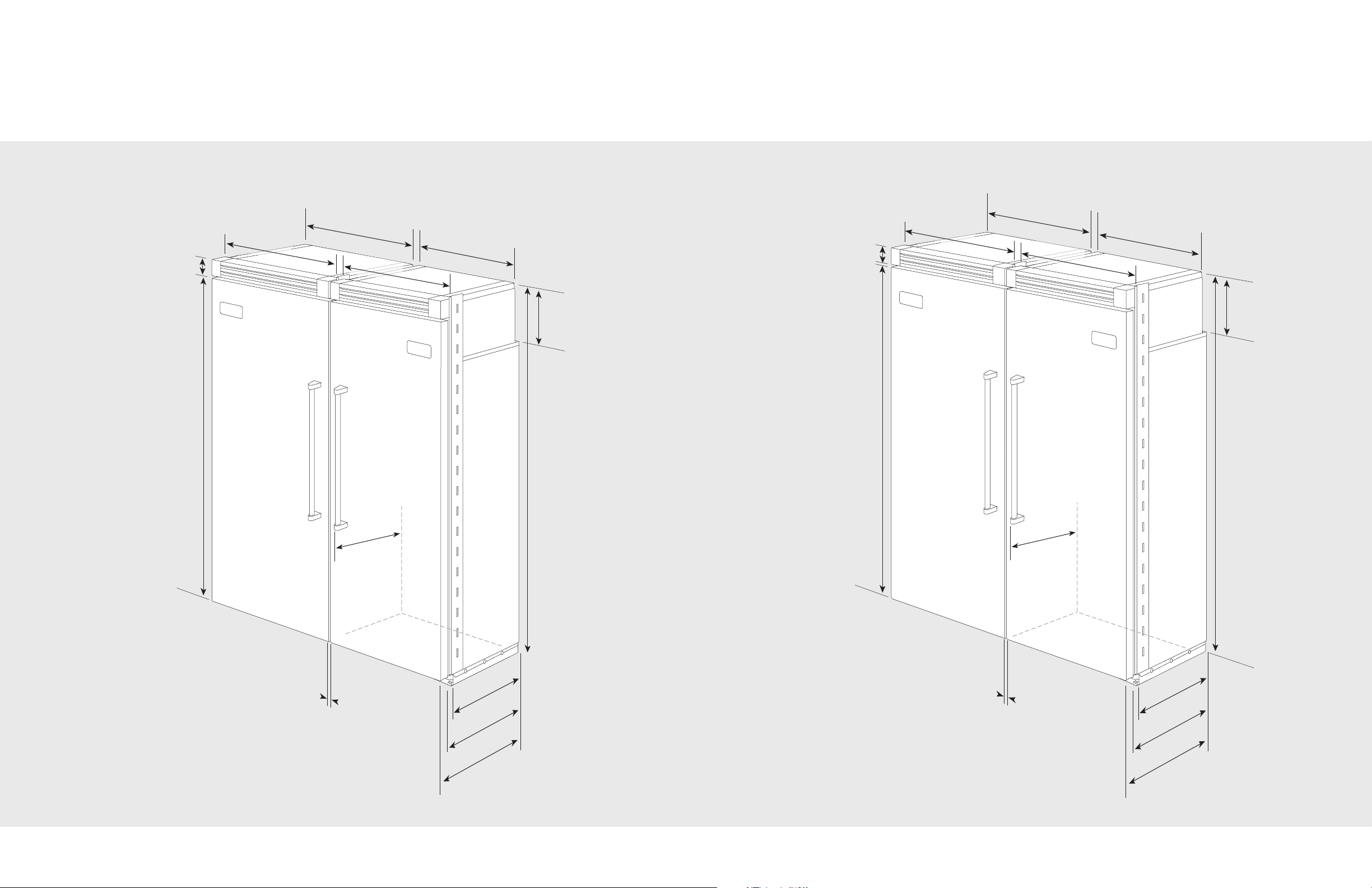
2
4
–
1
1
/
1
6
”
(
62
.7
c
m)
1”
(2.
54
cm)
Bet
wee
n U
ni
ts
3
5
”
(8
8
.9 c
m
)
36
”
(
9
1
.
5 cm
)
9
–
5
/
3
2
”
(23
.
3
c
m)
8
2
–
3
/
4
”
(2
1
0.2
c
m
)
m
in
.
t
o
84
–
1/
16
”
(21
3.
5
cm
)
m
ax
.
2
0
–
3
/
4
”
(5
2
.7
c
m
)
2
2
–3
/
1
6
”
(5
6
.4
c
m
)
2
9”
(7
3
.7 cm)
7
5
–1
5
/
1
6
”
(1
9
2 .
9 c
m
)
3–1
9/
3
2
”
(
9.
1
c
m
)
30
”
(
76
.
2 c
m
)
2
7–
1/4
”
(
69
.
2
c
m
)
24–
11
/
16
”
(62
.7 c
m
)
1”
(2.5
4 c
m)
Bet
ween
Un
its
9–5
/32”
(23
.3
c
m)
82
–
3
/
4
”
(
2
1
0
.
2
cm)
mi
n
.
to
84–
1/16
”
(
2
1
3.
5
cm
)
ma
x
.
20–
3/4”
(52
.7
c
m)
22
–3/
16”
(56
.4
cm
)
7
5–
1
5
/
16
”
(1
9
2
.
9
c
m
)
3
–1
9
/
3
2
”
(
9
.
1
c
m
)
2
9
”
(73
.7 c
m
)
2
9
”
(73
.7
c
m
)
3
0
”
(
7
6
.
2 c
m
)
30
”
(
76
.
2 cm
)
2
7–
1/4
”
(
69
.
2
cm
)
Dimensions
Dimensions
Dual 30” Professional
Dual 30” & 36” Professional
12
13
24–
11
/1
6
”
(62
.7 c
m
)
1”
(2.54
cm
)
Bet
wee
n u
nit
s
35”
(
88
.
9
c
m
)
3
5
”
(
8
8
.
9 c
m
)
3
6
”
(
91
.
5
c
m)
36
”
(
9
1
.
5
c
m
)
9–5/
32”
(23
.3
c
m)
82–
3/4”
(
21
0
.2
c
m
)
m
in
.
to
8
4–
1/1
6”
(
21
3.5
c
m
)
ma
x
.
20
–
3
/4
”
(52
.7
cm)
22
–3/
16”
(56
.4
cm)
75–
15/
16”
(19
2 .
9 c
m
)
3
–1
9
/3
2
”
(
9
.
1
c
m)
2
7
–
1/
4
”
(
69
.
2 cm
)
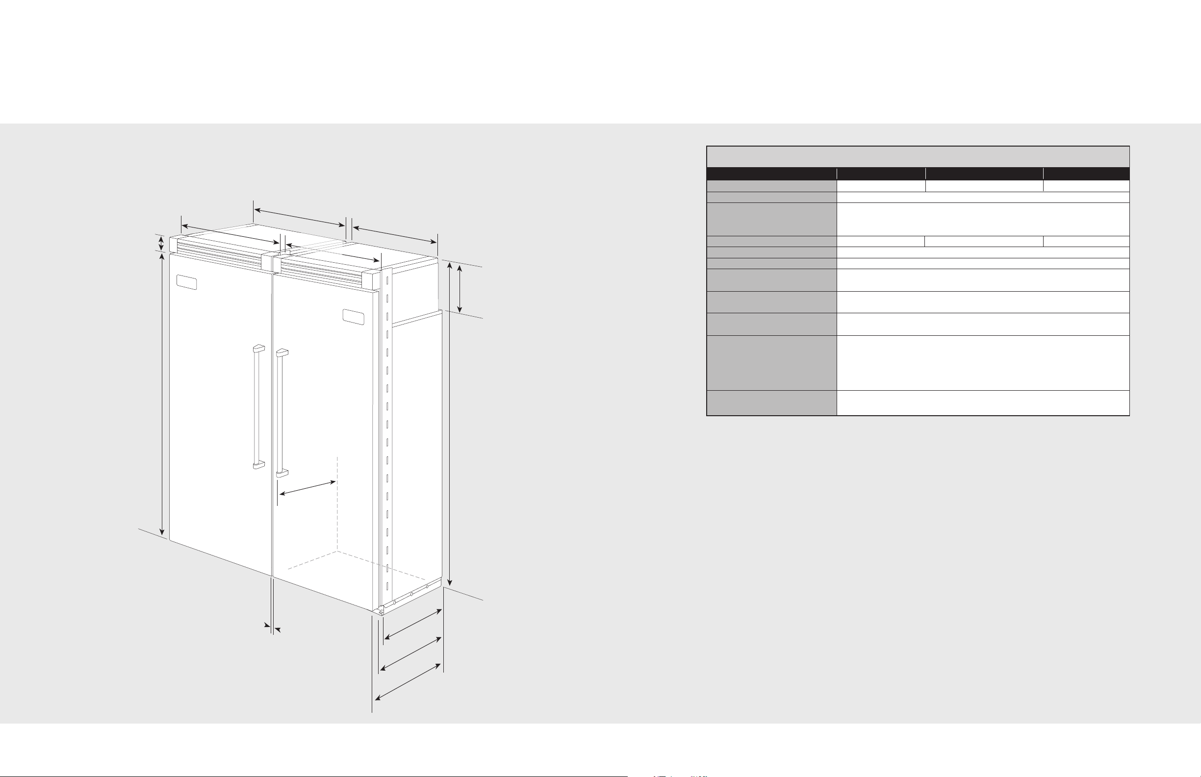
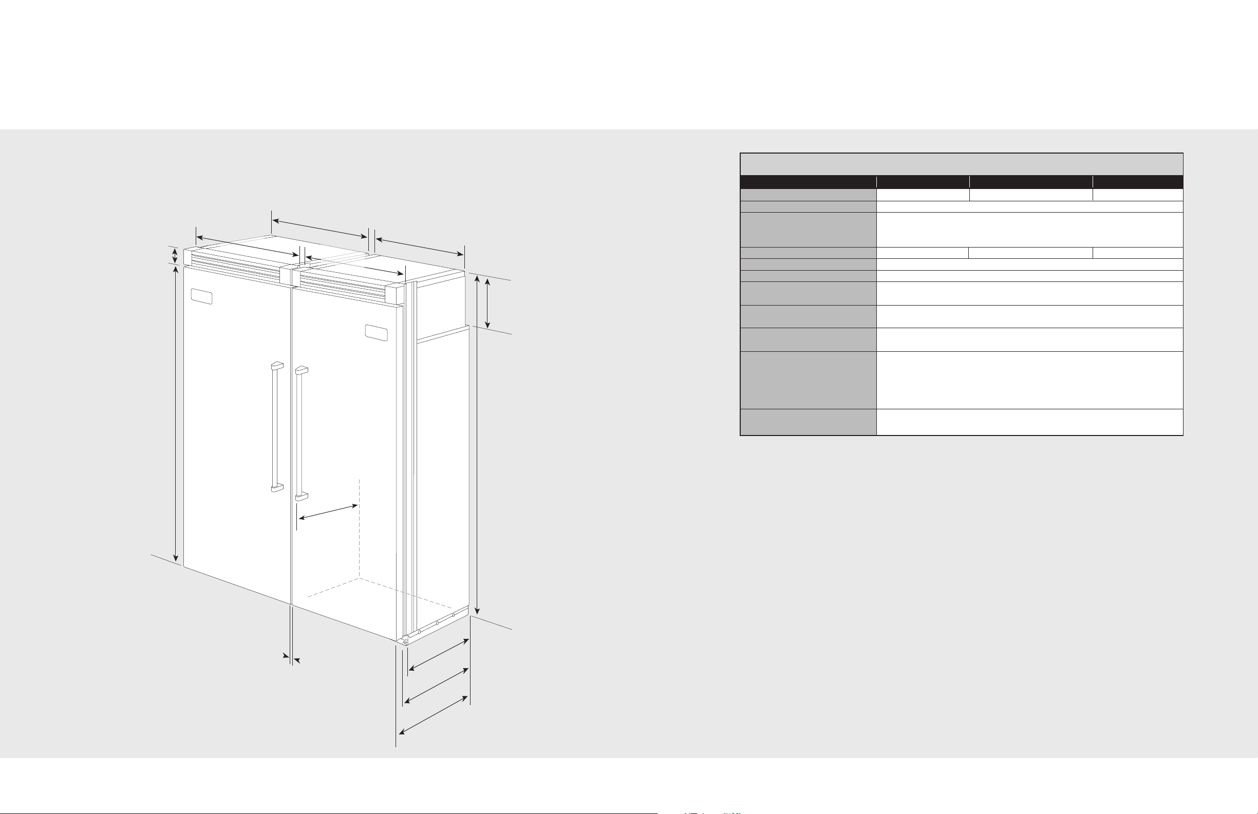
Dimensions
Specifications
Dual Professional
Dual 36” Professional
Description (2) 30” Units (1) 36” & (1) 30” Unit (2) 36” Units
verall width 60” (152.4 cm) 66” (167.6 cm) 72” (182.9 cm)
O
Overall height from bottom 82-3/4” (210.2 cm) min. to 84-1/16” (213.5 cm) max.
Overall depth from rear To front edge of side trim: 22-3/16” (56.4 cm)
To front of top grille: 24-11/16” (62.7 cm)
To front of handle endcap: 27-1/4” (69.2 cm)
Cutout width 59-1/2” (151.1 cm) 65-1/2” (166.4 cm) 71-1/2” (181.6 cm)
Cutout height 82-7/8” (210.5 cm) min. to 84-1/16” (213.5 cm) max.
Cutout depth 24” (61.0 cm) min.
Electrical requirements (2) 115 volt, 60 Hz, 15 amp dedicated circuit; 3-wire cord with
grounded 3-prong plug attached to product
Maximum amp usage 30” Freezer 9.1 amps per unit 30” Refrigerator 5.7 amps per unit
36” Freezer 9.5 amps per unit 36” Refrigerator 6.5 amps per unit
Inlet water requirements 1/4” copper tubing inlet waterline; minimum 20 psi;
(All Freezer only) maximum 120 psi
Overall interior dimensions
30” Freezer 15.9 cu. ft. (450 liters)
30” Refrigerator 18.2 cu. ft. (516 liters)
36” Freezer 19.1 cu. ft. (541 liters)
36” Refrigerator 22.8 cu. ft. (646 liters)
Approximate shipping weight 30”- Freezer 530 lbs. (238.5 kg) each; Refrigerator 505 lbs. (227.3 kg) each
36”- Freezer 585 lbs. (263.3 kg) each; Refrigerator 570 lbs. (256.5 kg) each
14
15
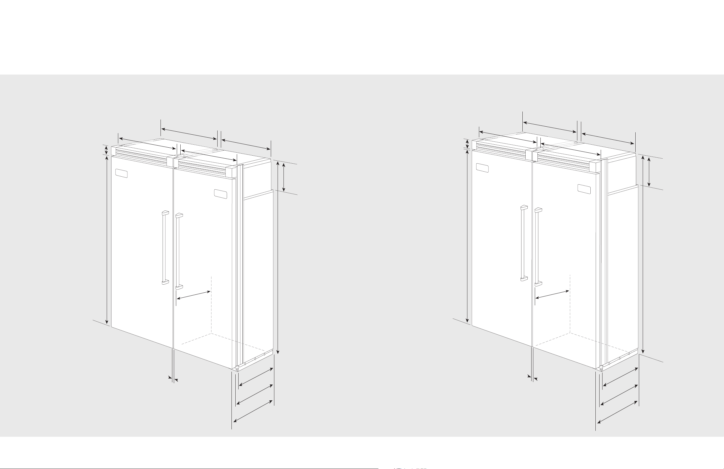
2
4
”
(
61
.0
c
m)
1”
(2.
54
cm)
B
et
wee
n Uni
ts
3
5
”
(8
8
.9
c
m
)
36
”
(
9
1
.
5 c
m
)
9
–
5
/32
”
(23
.
3
c
m)
8
2
–
3
/
4
”
(2
1
0.2
c
m
)
m
in
.
t
o
84–
1/
16
”
(21
3.
5
cm
)
m
ax
.
2
0
–
3
/
4
”
(5
2
.7
c
m
)
2
3
–
3
/
8
”
(5
9.4
c
m
)
2
9”
(7
3
.7 cm)
7
5
–1
5
/
1
6
”
(1
9
2 .
9 c
m
)
3–1
9/
3
2
”
(
9.
1
c
m
)
30
”
(
76
.
2 c
m
)
2
6–
1/2
”
(
67
.
3
c
m
)
24”
(61
.0
cm
)
1”
(2.5
4 c
m)
Bet
ween
Un
its
9–5
/32”
(23
.3
c
m)
82–
3
/
4
”
(
2
1
0
.2
cm)
mi
n
.
to
84
–
1
/
1
6”
(
2
1
3.5
c
m)
m
a
x
.
20–
3/4”
(52
.7
c
m)
23–
3/
8
”
(59
.4
cm)
7
5–
1
5
/
16
”
(1
9
2
.
9
c
m
)
3
–1
9
/
3
2
”
(
9
.
1
c
m
)
2
9
”
(73
.7 c
m
)
2
9
”
(73
.7
c
m
)
3
0
”
(
7
6
.
2 c
m
)
30
”
(
76
.
2 cm
)
2
6
–
1/
2
”
(
67
.
3
cm
)
Dimensions
Dimensions
Dual 30” Professional Integrated Dual 30” & 36” Professional Integrated
16
17
24”
(61
.0
cm
)
1”
(2.54
c
m)
Bet
wee
n uni
ts
35”
(
88
.
9
c
m
)
3
5
”
(
8
8
.
9
c
m
)
3
6
”
(
91
.
5 c
m)
36
”
(
9
1
.
5
cm
)
9–5/
32”
(23
.3
c
m)
82–
3/4”
(
21
0
.2
c
m
)
m
in
.
to
8
4–
1/1
6”
(
21
3.5
c
m
)
ma
x
.
20–
3/
4
”
(52
.7
cm)
23–
3/8”
(59
.4
cm)
75–
15/
16”
(19
2 .
9 c
m
)
3
–1
9
/3
2
”
(
9
.1
cm
)
2
6–
1/2
”
(
67
.
3
cm
)
Dimensions
Specifications
Dual 36” Professional Integrated
Description (2) 30” Units (1) 36” & (1) 30” Unit (2) 36” Units
verall width 60” (152.4 cm) 66” (167.6 cm) 72” (182.9 cm)
O
Overall height from bottom 82-3/4” (210.2 cm) min. to 84-1/16” (213.5 cm) max.
Overall depth from rear To front edge of side trim: 23-3/8” (59.4 cm)
To front of top grille: 24” (61.0 cm)
To front of handle endcap: 26-1/2” (67.3 cm)
Cutout width 60” (152.4 cm) 66” (167.6 cm) 72” (182.9 cm)
Cutout height 82-7/8” (210.5 cm) min. to 84-1/16” (213.5 cm) max.
Cutout depth 24” (61.0 cm) min.
Electrical requirements (2) 115 volt, 60 Hz, 15 amp dedicated circuit; 3-wire cord with
grounded 3-prong plug attached to product
Maximum amp usage 30” Freezer 9.1 amps per unit 30” Refrigerator 5.7 amps per unit
36” Freezer 9.5 amps per unit 36” Refrigerator 6.5 amps per unit
Inlet water requirements 1/4” copper tubing inlet waterline; minimum 20 psi;
(All Freezer only) maximum 120 psi
Overall interior dimensions
30” Freezer 15.9 cu. ft. (450 liters)
30” Refrigerator 18.2 cu. ft. (516 liters)
36” Freezer 19.1 cu. ft. (541 liters)
36” Refrigerator 22.8 cu. ft. (646 liters)
Approximate shipping weight 30”- Freezer 530 lbs. (238.5 kg) each; Refrigerator 505 lbs. (227.3 kg) each
36”- Freezer 585 lbs. (263.3 kg) each; Refrigerator 570 lbs. (256.5 kg) each
Dual Professional Integrated
18
19
 Loading...