

Page 1
Viking Installation Guide
Viking Range Corporation
111 Front Street
Greenwood, Mississippi 38930 USA
(662) 455-1200
For product information,
call 1-888-VIKING1 (845-4641)
or visit the Viking Web site at
vikingrange.com
F20880A EN
201/301/451 Series
Built-In Dishwashers
(051612)
Page 2
IMPORTANT3– Please Read and FollowTable of Contents
WARNING
WARNING
WARNING
WARNING
Warnings & Important Information _____________________________________________________3
Dimensions & Cutout Dimensions _____________________________________________________6
Specifications _______________________________________________________________________7
Custom Door Panel Specifications _____________________________________________________8
Custom Door Panel Installation Option _________________________________________________9
General Information ________________________________________________________________11
Site Preparation_________________________________________________________________11
Water Supply___________________________________________________________________11
Drain __________________________________________________________________________11
Electrical Connections_______________________________________________________________12
Hardwire Conduit Option (201 & 301 Models) ______________________________________13
Hardwire Conduit Option (451 Models) ____________________________________________13
Trim Installation Options (451 Models)_____________________________________________16
Counter Balance Spring Adjustment (If Necessary) __________________________________17
Installation_________________________________________________________________________18
Performance Checklist ______________________________________________________________22
Testing for Leaks ________________________________________________________________22
Final Preparation________________________________________________________________22
Service & Registration _______________________________________________________________23
• Before beginning–please read these
instructions completely and carefully.
• DO NOT remove permanently affixed
labels, warnings, or rating plates from the
dishwasher. This may void warranty or
create an unsafe product.
• Please observe all national and local
codes.
Make sure that incoming voltage is the
same as unit rating. An electric rating
plate specifying voltage, hertz, and amps
is attached to the product. Wiring the
dishwasher with more voltage than it is
rated for may cause severe damage. To
reduce the risk of fire, electric shock, or
injury to persons, installation work and
electrical wiring must be done by qualified
technician in accordance with all
applicable codes and standards, including
fire-rated conditions.
• Please ensure that this product is properly
grounded.
• The installer should leave these
instructions with the consumer who should
retain for local inspector’s use and for
future reference.
• The dishwasher has a factory installed
backflow preventer. Do not add an
additional check valve.
• Failure to provide a 20” above floor level
(50.8 cm) high loop may result in improper
operation of the dishwasher.
• Remove pallet screws from base. Damage
could occur to dishwasher if screws are not
removed.
Plumbing connections must comply with
applicable sanitary, safety and plumbing
codes.
Electrical power must be turned off at
circuit breaker or fuse box before making
electrical connections. Disconnect the
electrical power supply and place a tag at
the disconnect switch indicating that you
are working on the circuit.
Site Preparation
2
It is recommended that a thorough site inspection be
conducted PRIOR to unpacking and moving this appliance.
The dishwasher door may not stay open
by itself until the door panel is installed.
Be aware of this when fastening the
dishwasher to the cabinet.
Page 3
IMPORTANT–Please Read and Follow!
WARNING
WARNING
WARNING
WARNING
WARNING
WARNING
WARNING
CAUTION
ELECTRICAL SHOCK HAZARD
• Electrically ground dishwasher.
• Connect ground wire to green ground
connector in terminal box.
• DO NOT use an extension cord.
• Failure to follow these instructions, can
result in death, fire or electrical shock.
TIP OVER HAZARD
• DO NOT use dishwasher until
completely installed.
• DO NOT push down on open door.
• Doing so can result in serious injury
or cuts.
EXCESSIVE WEIGHT HAZARD
Use two or more people to move and
install dishwasher. Failure to do so can
result in back or other injury.
Disconnect the electrical power supply and
place a tag at the disconnect switch
indicating that you are working on the
circuit.
Be sure electrical power is turned off at
circuit breaker or fuse box before servicing
or installing unit. Do not use an extension
cord for this appliance.
Improper connection of the equipment –
grounding conductor can result in a risk of
electric shock. Check with a qualified
electrician or serviceman if you are in
doubt as to whether the appliance is
properly grounded. Do not modify the plug
provided with the appliance; if it will not fit
the outlet, have a proper outlet installed by
a qualified electrician.
IMPORTANT5– Please Read and Follow
A GFI shall be used if required by NFPA-70
(National Electric Code), federal/state/local
laws, or local ordinances.
• The required use of a GFI is normally
related to the location of a receptacle with
respect to any significant sources of water
or moisture.
• Viking Range Corporation will NOT
warranty any problems resulting from GFI
outlets which are not installed properly or
do not meet the requirements below.
If the use of a GFI is required, it should be:
• Of the receptacle type (breaker type or
portable type NOT recommended)
• Used with permanent wiring only
(temporary or portable wiring NOT
recommended)
• On a dedicated circuit (no other
receptacles, switches or loads in the
circuit)
• Connected to a standard breaker of
appropriate size (GFI breaker of the same
size NOT recommended)
• Rated for Class A (5 mA +/- 1 mA trip
current) as per UL 943 standard
• In good condition and free from any
loose-fitting gaskets (if applicable in
outdoor situations)
• Protected from moisture (water, steam,
high humidity) as much as reasonably
possible
Plumbing connections must comply with
applicable sanitary, safety, and plumbing
codes.
The dishwasher has a factory installed
backflow preventer. Do Not add an additional
check valve.
4
Page 4
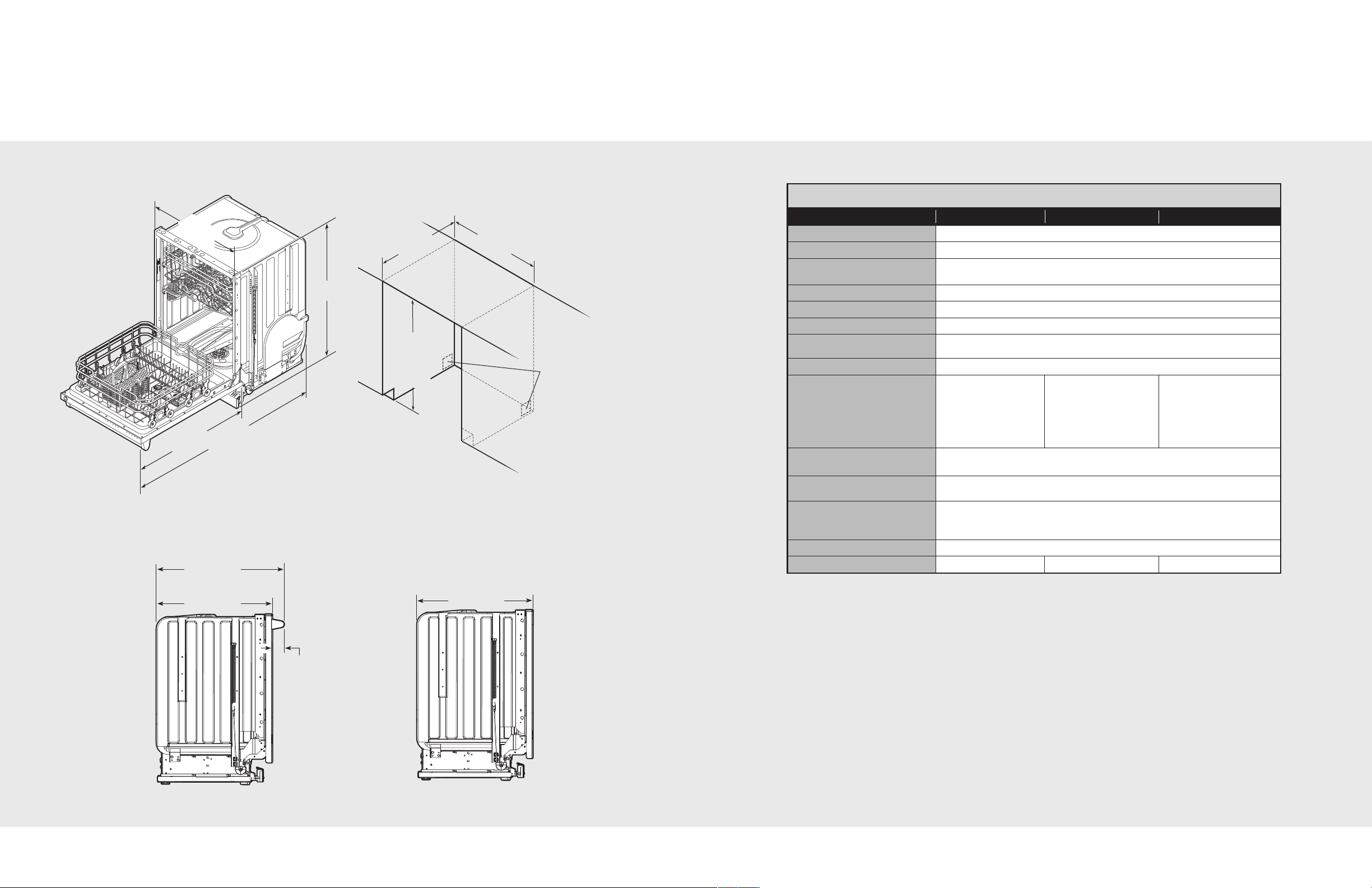
Dimensions & Cutout Dimensions
2
8
-
3
/4
”
(7
3
.0
c
m
)
3
3
-
7
/8
”
(8
6
.0
c
m
)
4
9
”
(1
2
4
.5
c
m
)
2
3
-
7
/
8
”
(
6
0
.
6
c
m
)
23-5/8”
(60.0 cm)
3”
(7.6 cm)
23-5/8”
(60.0 cm)
26-5/8”
(67.6 cm)
2
4
”
(
6
1
.
0
c
m
)
2
4
”
(
6
1
.
0
c
m
)
3
4
”
m
i
n
.
(
8
6
.
4
c
m
)
t
o
3
5
”
m
i
n
.
(
8
9
.
0
c
m
)
Note: A 2” (5.1 cm)
cut-out is required
for water supply
and discharge lines.
Custom PanelProfessional
Specifications
Built-In Dishwasher
Description
Overall width
Overall height from floor
Overall depth from rear
Cutout width
Cutout height
Cutout depth
Electrical requirements
Water-heating element rating
Inlet water temperature
Inlet water pressure
operating range
Inlet water hose
Drain hose
Drain hose high loop required
Approximate shipping weight
201 Models 301 Models 451 Models
120°F (49°C) required 120°F (49°C) required 120°F (49°C)
5’
(1.5 m) braided stainless steel water line with 3/8” (0.95 cm) compression
7’ (2.13 m) 1/2” (1.3 cm) ID “crimp-proof” flexible drain hose attached to
dishwasher, connections provided for 5/8” (1.6 cm),
147 lbs. (66.7 kg) 152 lbs. (68.9 kg) 157 lbs. (71.2 kg)
23-7/8” (60.6 cm)
33-7/8” (86.0 cm) min. to 35” (89.0 cm) max.
To edge of side – 23-5/8” (60.0 cm) – includes door panel
With door open – 49” (124.5 cm)
24” (61.0 cm)
34” (86.4 cm) min. to 35” (89.0 cm) max.
24” (61.0 cm)
15.0 amps, 120VAC/60 Hz;
3’9” (1.1 m) electrical cord
10 to 125 psi (0.69 to 8.62 bar)
fitting connected to dishwasher
1” (2.5 cm), cut as required
Height from floor – 20” (51.0 cm) min.
3 prong plug supplied with unit.
1200 watts
recommended;
Dishwasher will perform
properly with cold water.
Note: Cycle times
will vary.
3/4” (1.9 cm) or
6
7
Page 5
2
2
1
1
x2
4
x2
3
Locators
2
x4
1
1
3
1
1
1
1
4
2
x4
29-3/4”
(75.6 cm)
to
31-1/4”
(79.4 cm)
22-21/32”
(57.5 cm)
23-9/32"with trim
(59.1 cm)
or
23-7/8” without trim
(60.6 cm)
14”
(35.6 cm)
22-5/32”
(56.3 cm)
13-1/2”
(34.3 cm)
10-5/8”
(27.0 cm)
ø1/8” 4 places
(0.3 cm)
Locator
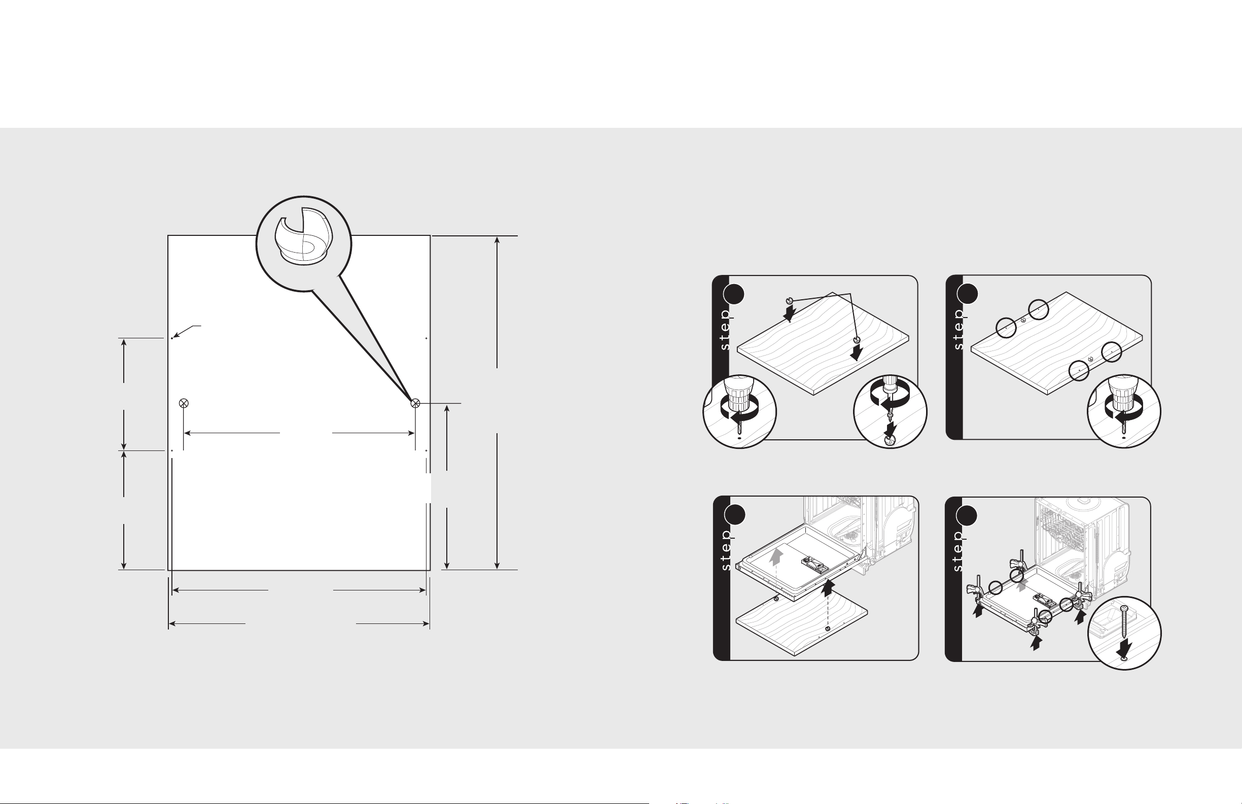
Custom Door Panel
(Specifications for FDB301/FDB451 Models)
Custom Door Panel (Installation Option)
Have the overlay panel constructed per dimensions.
The panel thickness MAY NOT exceed 3/4" (1.91 cm)
for flush installation in most cabinets. Ensure that the
design, construction, and installation of the panel
overlay and its handle mounting is sufficient to reliably
operate in this application with a maximum panel
weight of 18 lbs. (8.2 kg.) Custom panels should not
exceed 18 lbs. (8.2 kg.)
Note: Back side of panel shown. Use caution not to drill through front of panel.
Note: If panels are made longer than 29-3/4” (75.6 cm), the door panel will be taller than dishwasher control panel.
Note: All hole location dimmensions should be measured from the bottom of the door per the illustration above.
8
Pre-drill two holes with 1/8” drill bit for the locators
using dimensions shown in the figure. Attach plastic
locators using the Torx (T20 BIT) pan head screws
provided in the hardware package.
Use locators to align the panel to the
dishwasher door holes.
Pre-drill other four locations for wood screws
to attach the panel to the dishwasher door using
the dimensions shown in the figure.
Use non-marring clamps to hold custom panel in place.
Use the truss head 1-3/4” long screws provided in the
hardware package for the panel attachment.
Note: If you are using any special panel material
and that require special screws, always use a #8 1-3/4”
long truss head Torx stainless steel screws. The screws
MUST BE stainless steel to avoid corrosion.
9
Page 6
WARNING
CAUTION
5
x4
Verify operation of the door counter
balance springs after installation of
the overlay panel. The additional
weight of the overlay panel might
require an adjustment to the preload
of the counterbalance springs. If
adjustment of the springs is required,
please refer to the “Counter Balance
Spring” section.
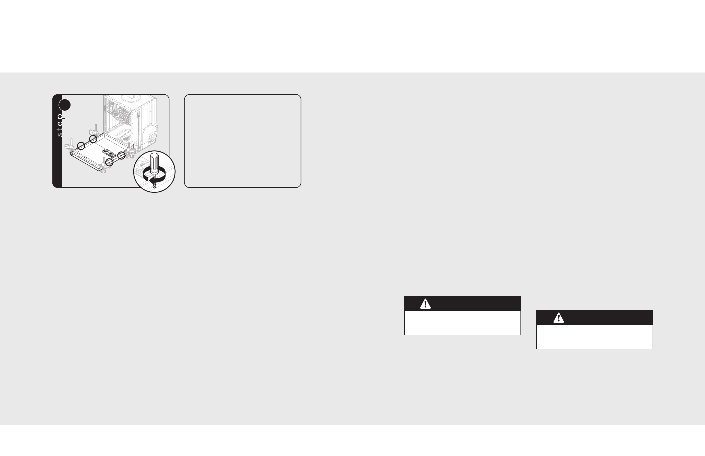
Custom Door Panel (Installation Option, cont.)
General Information
Carefully tighten each screw to secure the overlay
and check to ensure that the overlay is square with the
dishwasher door and cabinet opening and that the panel
doesn’t interfere with the operation of the dishwasher.
• Read these instructions carefully and
completely before installing the
dishwasher. The installation should be
carried out by a qualified installer, who is
familiar with all local codes and ordinances
for electrical and plumbing connections. If
the dishwasher is being installed for the
first time, most of the work has to be done
before you move it into place. If you are
replacing an old dishwasher, you must
check the old connections.
• Electrical requirements are listed in the
“Specifications” section.
Site Preparation
Note: It is recommended that a thorough
site inspection be conducted PRIOR to
unpacking and moving this appliance.
• After determining where the water
supply line will connect to the
dishwasher, provide a 2” (5.1 cm) access
hole and run the line to the approximate
fill valve location. Sealing access area
once lines are in place is recommended.
• Confirm available access to adequate power.
Water Supply
• For service convenience, a shut-off valve
(not supplied) should be installed in the
supply line in a readily accessible location
(such as beneath the sink).
• It is recommended that the dishwasher
be connected to a hot water supply.
Only the 451 model can be connected to
the cold water supply. Cycle times will
increase.
• It is important that the water supply line
and the shut-off valve have a sufficient flow
volume. Flush the supply line prior to
connecting it to the intake line of the
dishwasher.
• Make sure the connection is sealed and not
leaking before completing the installation.
Drain
• The access hole for the drain line should
be 2” square (5.1 cm). Locate as low and
as near to the back wall as possible.
• DO NOT use any fittings anywhere in the
drain line that are less than 1/2” (1.3 cm) ID.
• If the drain line is going to be connected
to a food waste disposer, be sure to
remove the knockout or plug from the
fitting before connecting drain line.
• Drain connection should be a minimum of
9” (22.9cm) from the floor. If connection is
lower, siphoning during cycle can occur.
10
Plumbing connections must comply with
applicable sanitary, safety, and plumbing
codes.
• Water pressure for the water supply should
be a minimum of 10 to 125 psi. The
dishwasher is supplied with a 5’ (1.5 m)
braided stainless steel water line with 3/8”
(0.95 cm) compression fitting connected to
dishwasher.
• After determining where the water supply
line will connect to the dishwasher, provide
a 2” (5.1 cm) access hole and run the
water supply line to the approximate fill
valve location.
The dishwasher has a factory installed
backflow preventer. Do Not add an additional
check valve.
Note: The end of the drain hose is 1” (2.5 cm),
but is adjustable to 3/4” (1.9 cm) or 5/8”
(1.6 cm). If the drain connection is smaller
than 1” (2.5 cm), the hose can be cut to fit
the connection.
Note: Be sure to run the drain line through
the hole to the sink compartment before
moving the dishwasher into place.
11
Page 7
5
1
2
1
1
6
2
Black
(Line)
White
(Neutral)
1
3
2
x4
2
1
3
3
x2
2
1
4
Electrical Connections
WARNING
WARNING
WARNING
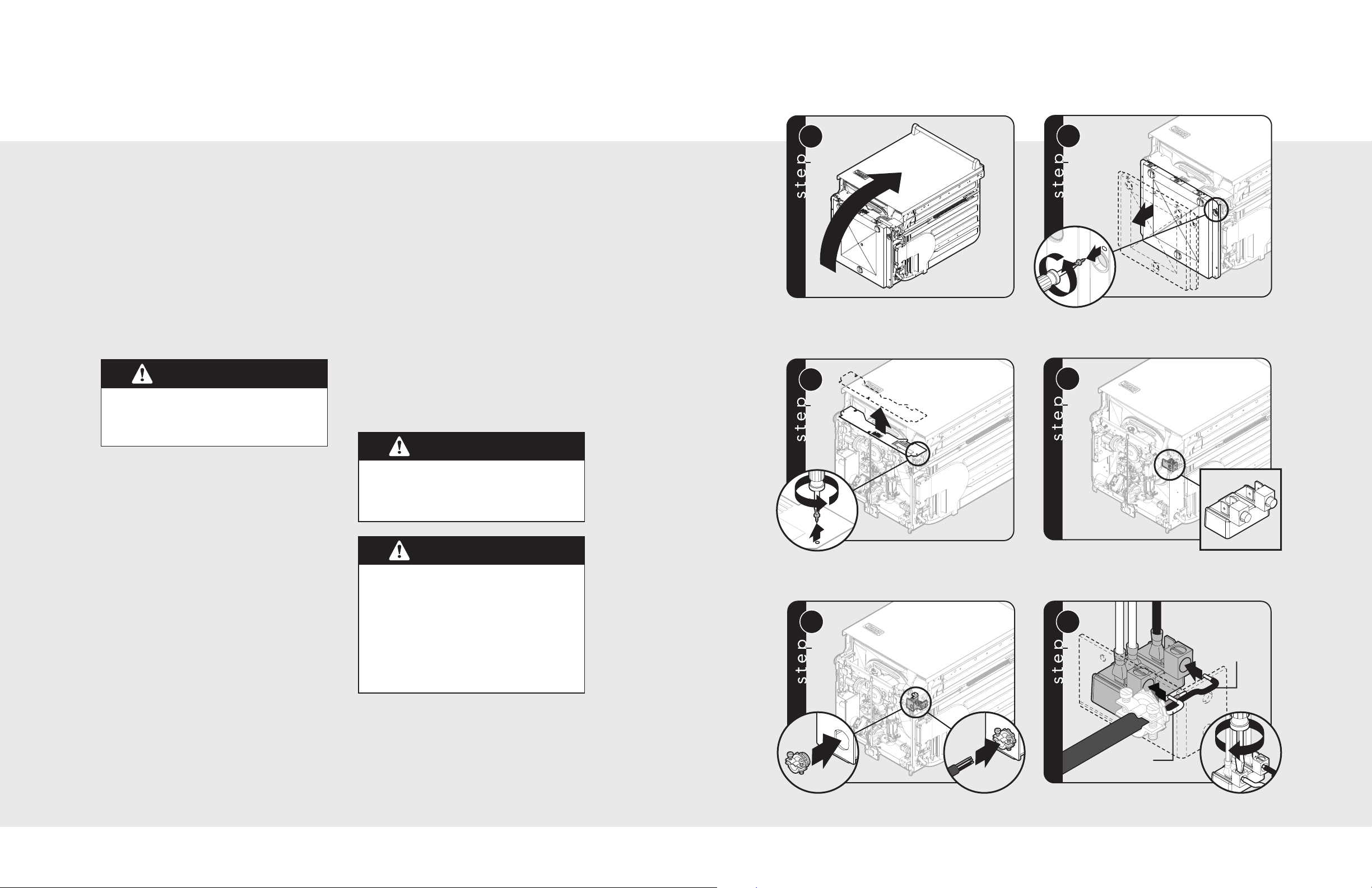
Hardwire Conduit Option (201 & 301 Models)
Grounding Instructions
This appliance must be grounded. In the
event of a malfunction or breakdown,
grounding will reduce the risk of electric
shock by providing a path of least resistance
for electric current. This appliance is
equipped with a cord having an equipmentgrounding conductor and a grounding plug.
The plug must be plugged into an
appropriate outlet that is installed and
grounded in accordance with all local codes
and ordinances.
Disconnect the electrical power supply and
place a tag at the disconnect switch
indicating that you are working on the
circuit.
Grounding Instructions if Hardwired:
This appliance must be connected to a
grounded metal, permanent wiring system;
or an equipment grounding conductor must
be run with the circuit conductors and
connected to the equipment – grounding
terminal or lead on the appliance.
• For a cord connected undercounter
dishwasher:
1. The power supply receptacle for the
appliance should be installed in a
cabinet or on a wall adjacent to the
under counter space in which the
appliance is to be installed;
2. There should be an opening through
the partition between the
compartments mentioned in Item (1),
that is large enough for the attachment
plug to pass through. The longest
dimension of the opening shall not be
more than 1-1/2” (38 mm).
3. The edges of the opening mentioned in
Item (2) should, if the partition is wood,
be smooth and rounded or, if the
partition is metal, be covered with the
grommet provided for this purpose by
the manufacturer; and
4. Care should be exercised, when the
appliance is installed or removed to
reduce the likelihood of damage to the
power supply cord.
• The dishwasher comes with a 3’9” (1.1 m)
electrical cord for 110-120 volts, 15/20
amp supply. This cord should be plugged
into the 110-120 volt outlet located under
the sink.
• If the cord is not long enough or if a hard
wire installation is needed, follow the
instructions in the “Hardwire” section.
Note: Access holes should be 2” square
(5.1 cm) with no sharp edges.
• In a hardwire installation, use only copper
supply conductors. The conductors should
have a minimum temperature rating of
194° F (90° C).
Be sure electrical power is turned off at
circuit breaker or fuse box before servicing
or installing unit. Do not use an extension
cord for this appliance.
Improper connection of the equipment –
grounding conductor can result in a risk of
electric shock. Check with a qualified
electrician or serviceman if you are in
doubt as to whether the appliance is
properly grounded. Do not modify the plug
provided with the appliance; if it will not fit
the outlet, have a proper outlet installed by
a qualified electrician.
12
Remove any loose items in the dishwasher and carefully
lay the dishwasher on its back. Note: Be careful not to
pinch hoses or power cord beneath dishwasher.
Remove front plate.
Attach UL approved 3/4” strain relief (not included) to
bottom of terminal box. Run wires through strain relief.
Remove bottom pan. Note: Rapid removal of the bottom pan will
cause damage to the moisture sensor. For installation and servicing,
slowly pull the bottom pan from the unit and disconnect the wire
from the moisture sensor, which is located in the center of the pan.
Remove factory installed power
cable from terminal block.
Connect wires to terminal block.
13
Page 8
5
1
2
1
1
6
2
Black
(Line)
White
(Neutral)
1
7
2
3
Green
(Ground)
2
8
1
x4
3
4
1
7
2
3
Green
(Ground)
2
8
1
x4
3
4
1
3
2
x4
2
1
3
3
x2
2
1
3
4
2
1
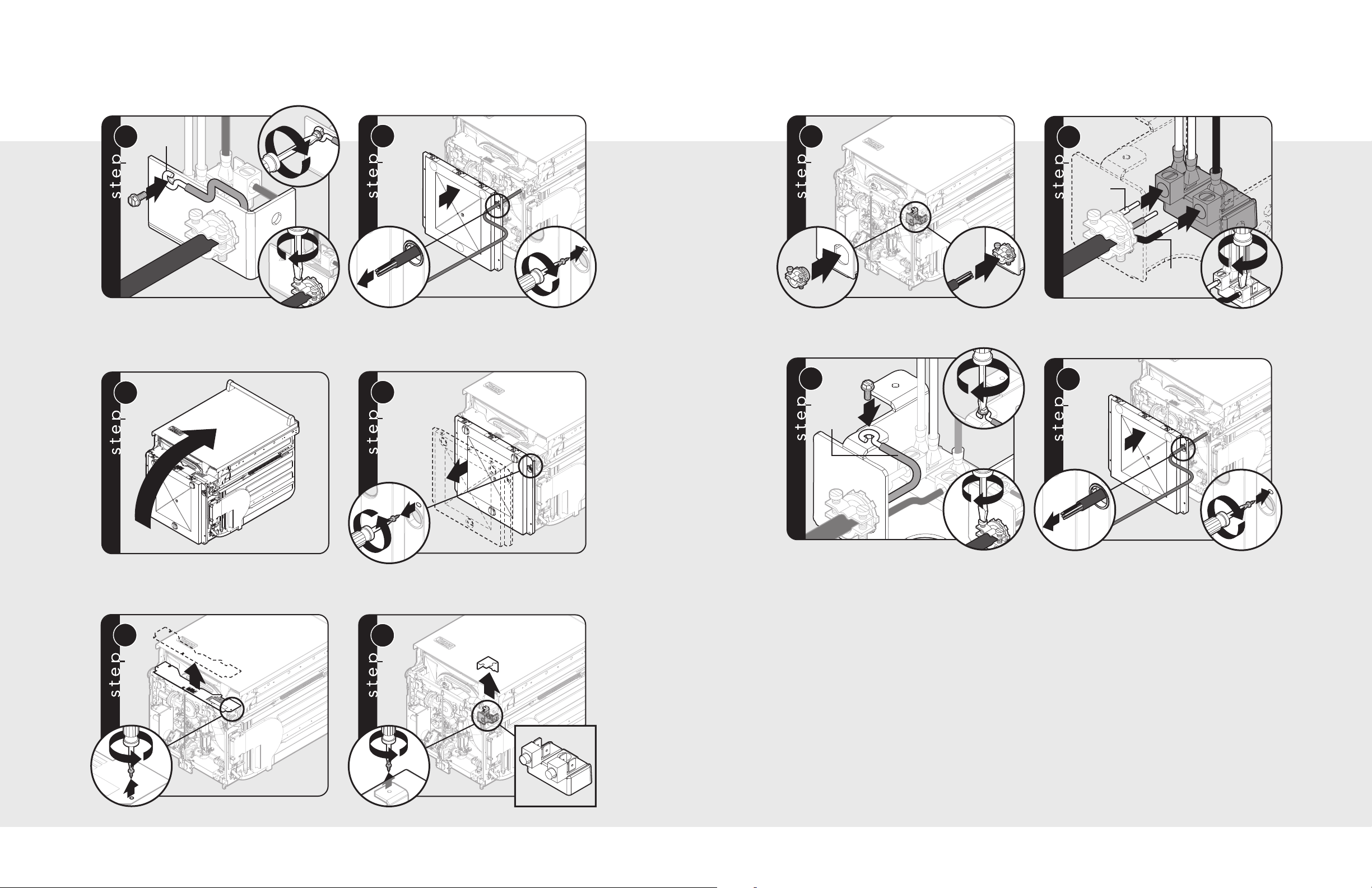
Hardwire Conduit Option (201 & 301 Models, cont.)
Hardwire Conduit Option (451 Models, cont.)
Connect ground wire. Tighten screws on strain relief.
NNoottee
: Reinstall front plate.
Run wire through grommet on bottom pan.
Hardwire Conduit Option (451 Models)
Remove any loose items in the dishwasher and carefully
lay the dishwasher on its back. Note: Be careful not to
pinch hoses or power cord beneath dishwasher.
Remove bottom pan. Note: Rapid removal of the bottom pan will
cause damage to the moisture sensor. For installation and servicing,
slowly pull the bottom pan from the unit and disconnect the wire from
the moisture sensor, which is located in the center of the pan.
Replace bottom pan.
Attach UL approved 3/4” strain relief (not included) to
bottom of terminal box. Run wires through strain relief.
Connect ground wire. Tighten screws on strain relief.
NNoottee
: Reinstall terminal block cover and front plate.
Connect wires to terminal block.
Run wire through grommet on bottom pan.
Replace bottom pan.
Remove front plate.
Remove terminal block cover. Remove factory installed
power cable from terminal block.
14
15
Page 9
1
1
2
1
2
2
3
Increase
tension
Decrease
tension
1
4
2
Note: For custom panel installation,
the door may require adjustment
to the preload of the counterbalance
springs. Follow these steps to
adjust the tension.
1a
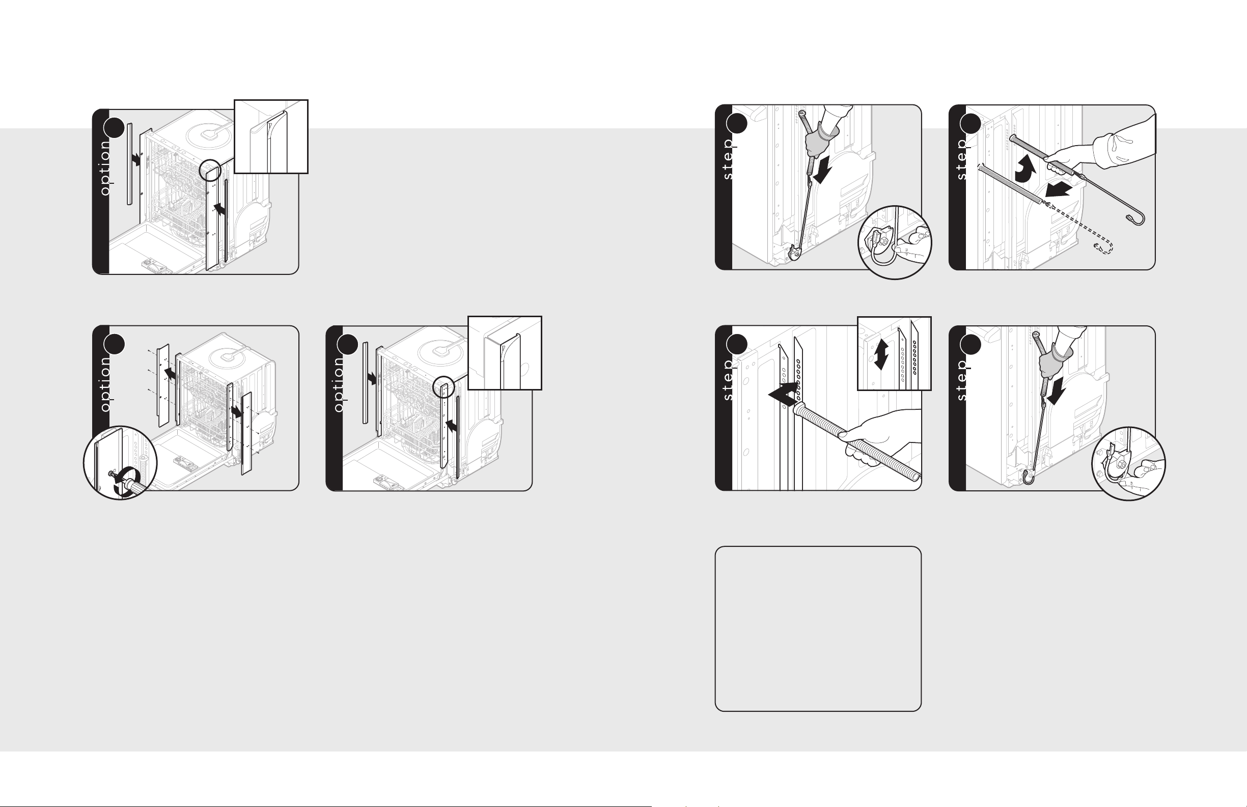
Trim Installation Options (451 Models)
2
2
1b
1
x6
2b
Counter Balance Spring Adjustment (if necessary)
Dishwasher ships with trim installed for flush install. If
needed, attach wiper gasket to dishwasher by pulling
protective film off adhesive back. Apply behind
hemmed edge of side trim.
To install dishwasher without trim, remove
the 6 screws (3 per side) and remove trim.
If needed, attach wiper gasket to dishwasher by pulling
protective film off adhesive back. Apply to leading
edge of dishwasher frame. Trim gasket to fit.
Disconnect cable from hook.
Set counter balance spring connector in appropriate
location.
Remove spring from dishwasher.
Reconnect cable to hook.
16
17
Page 10
2
1
6
D
O
W
N
U
P
7a
DO
W
N
U
P
DO
W
N
U
P
DO
W
N
U
P
DO
W
N
U
P
DOWN UP
Equal distance
7b
W
N
U
P
W
N
U
P
W
N
U
P
W
N
U
P
W
N
U
P
W
N
U
P
W
N
U
P
W
N
U
P
1
2
Equal distance
8
Installation
2
2
1
x4
3
4
1
2
1
2
3
1
1
4a
2
x2
1
1
4b
2
x2
5
Installation (cont.)
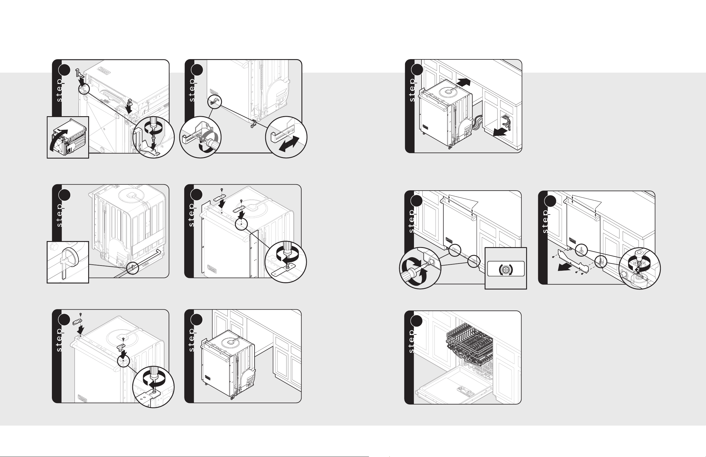
Carefully lay dishwasher on its back and attach the kick
plate brackets. Screws for the brackets will already be
in the base.
NNoottee
: Be careful not to pinch hoses or
power cord beneath dishwasher.
Using tie strap attached to dishwasher, band water line,
drain line, and power cord together.
To adjust the depth of the kick plate, loosen screws on
the bracket and position in the required depth. Tighten
screws and repeat for other side.
For installation with trim, attach brackets with two
screws (1 per bracket).
Slide unit into opening; be sure to feed water, electrical
and discharge lines into adjacent cabinet.
Leveling
For 301 & 451 models, place a level on handle, then
adjust to appropriate height. Left and right adjust side
to side and center adjusts front to back.
For 201 models, remove front panel to access the front
leveling legs. Leveling legs will be raised during
shipping. Adjust front leveling legs down using a 1/4
drive ratchet. When the adjustment nut is visible,
complete the lowering of the legs from the top. When
the legs are down, tighten the locking nut on the top
of the leg. To level center rear leg, see Step 7a.
For installation without trim, attach brackets with two
screws (1 per bracket).
Position unit in front of cutout.
18
To check level, front to back, pull the top rack half-way out of
unit. The rack should remain stationary and not move in or out.
Note: Leveling is important for optimal performance.
19
Page 11
12c
Air Gap
12d
A
ir Gap
13
14
9a
x2
3
1
2
x4
9b
x2
Minimum
20”
(50.8 cm)
from floor
10
1.0”
(2.5 cm)
Cut here for
3/4” (1.9 cm)
Cut here for
5/8” (1.6 cm)
11
12a
12b
Final Installation
Final Installation (cont.)
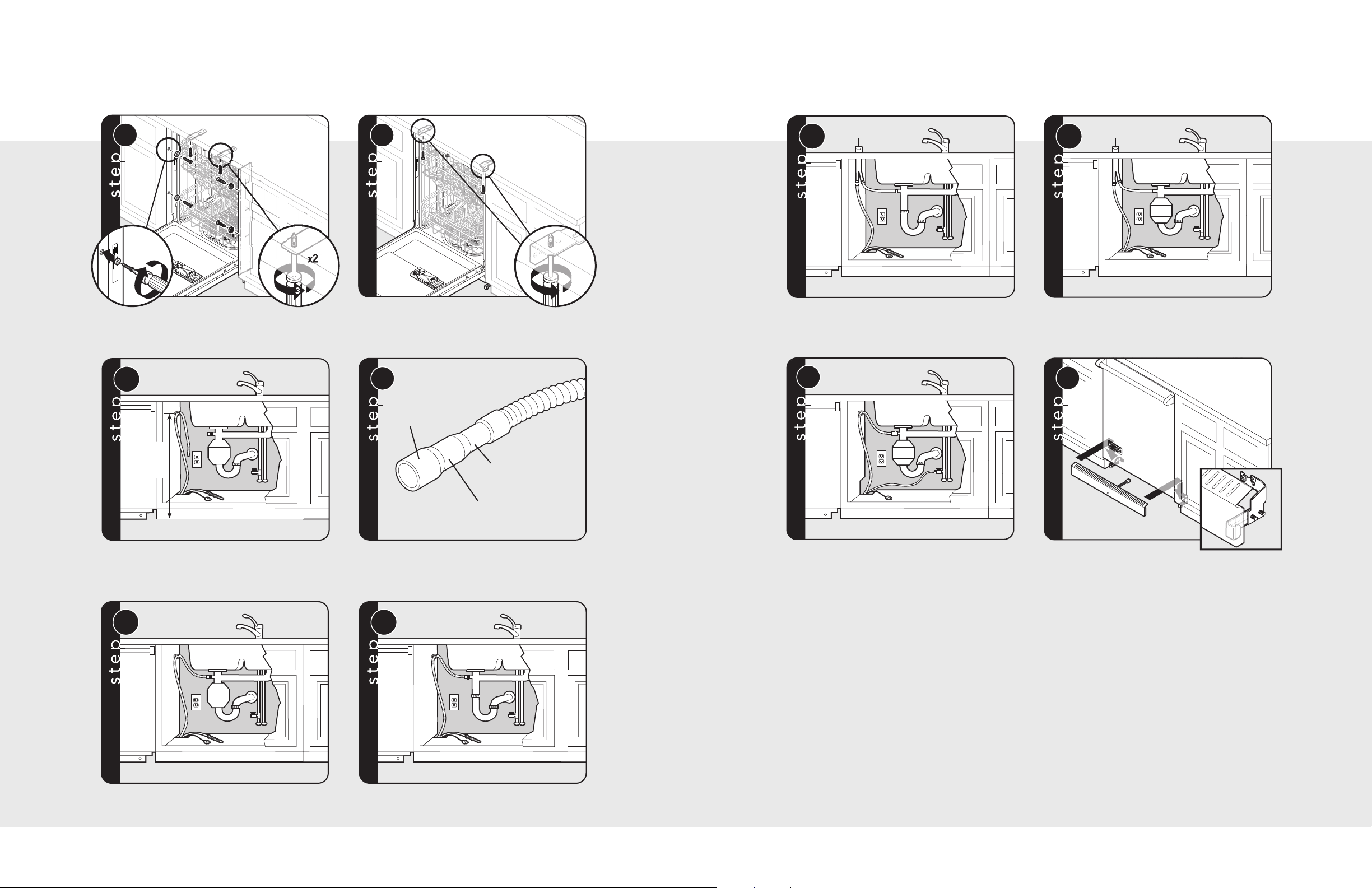
For installation with trim, secure dishwasher by
attaching provided mounting plugs and wood screws
through trim panels into cabinets. Attach screws
through top brackets into cabinets.
Install High Loop Clip, which is provided, a minimum of
20” (50.8 cm) from the floor. Refer to the Drain section
of "General Information" for proper installation
requirements.
For installation without trim, secure dishwasher by
attaching screws through top brackets into cabinets.
Identify discharge connection size; cut line to correct
size and connect. Clamp if necessary.
(Discharge with air gap)
Connect water line.
(Discharge with food waste disposer and air gap)
Plug LED light into dishwasher (select models only)
and install kick plate.
Note: DO NOT block the dry air exhausts (rectangular
slots on the access panel) with kick plate or base board.
Blocking the opening could reduce the dry performance
and cause unwanted condensation.
(Discharge with food waste disposer)
Note: Be sure to remove the knockout or plug from the
fitting of the disposer before connecting drain line.
20
(Standard discharge)
21
Page 12
POTS
PANS
CYCLES
NOR MAL
WAS H
LIGHT
CHINA
FAS T
WAS H
RINSE
HOLD
CLEAN
H
I TE MP
W
ASH
SANITIZED
TOP
WAS H
SANITIZED
155 F R INSE
DEL AY
S
TAR T
OPTIONS
Va ri-P res s ure Intelli-Was h
Quiet Clean S ystem
Airflo Gentle Dry
2
4
6
8
10
Performance Checklist
Service & Registration
Testing for Leaks
A qualified installer should carry out the following
checks:
Unit Reset
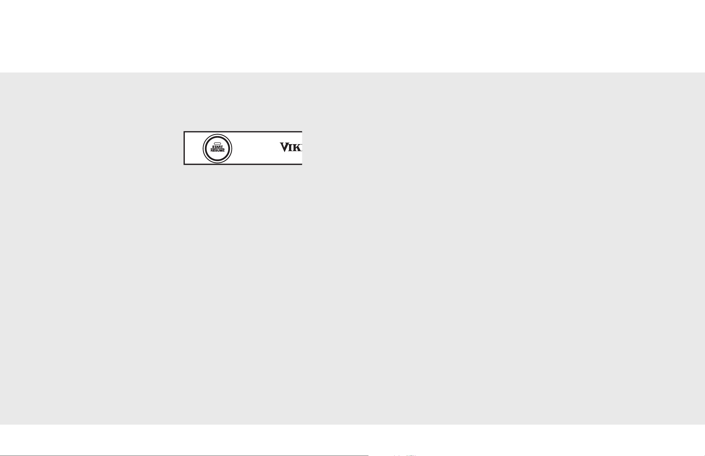
• If the unit should need to be reset for any
reason, push and hold the “START” button for
4 seconds.
h Remove packaging and parts.
h Turn on the water supply and check for leaks.
h Turn the power on at breaker/fuse box and
test the dishwasher operation by running a
rinse and hold cycle. (This should take about
12 minutes.)
h Turn off the electrical power and check for
leaks under the dishwasher.
h Make sure that no kinks have developed in
the drain lines.
Final Preparation
• Some stainless steel parts may have a plastic
protective wrap which must be peeled off.
Only authorized replacement parts may be used in performing service on the appliance. Do not
repair or replace any part of the appliance unless specifically recommended in the manual. All
servicing should be referred to a qualified technician.
Contact Viking Range Corporation, 1-888-VIKING1 (845-4641), for the nearest service parts
distributor in your area or write to:
VIKING RANGE CORPORATION
PREFERRED SERVICE
1803 Hwy 82W
Greenwood, Mississippi 38930 USA
The serial number and model number for your dishwasher are located on the identification plate mounted
on the bottom left side of the dishwasher door opening.
Record the following information indicated below. You will need it if service is ever required.
Model number ____________________________________________________________________________________
Serial number _____________________________________________________________________________________
Date of purchase __________________________________________________________________________________
22
Date installed ______________________________________________________________________________________
Dealer's name _____________________________________________________________________________________
Address ___________________________________________________________________________________________
These installation instructions should remain with the
dishwasher for future reference.
23
 Loading...