

Page 1
Page 1
Pb200i User Guide
For Sales & Service Contact
2650 E. 40th Ave. • Denver, CO 80205
Phone 303-320-4764 • Fax 303-322-7242
1-800-833-7958
www.geotechenv.com
April, 2018
Software V3.2 or later
Before operating the Pb200i, be sure to read this entire User’s Guide. We strongly recommend that you store this User’s Guide with the instrument in its carrying case.
Page 2

Page 2
Contents
Pb200i Features .......................................................................................................................................................... 3
Charging the Batteries ............................................................................................................................................... 5
Installing the Batteries ................................................................................................................................................ 5
Powering On and Initializing the Pb Application Software .................................................................................... 7
Taking a Measurement .............................................................................................................................................. 8
Testing the Accuracy and Precision of the Pb200i ................................................................................................ 9
Performing an Inspection with the Pb200i ............................................................................................................. 10
Using the Internal Read Through Adaper (IRTA) ................................................................................................. 12
Data Entry Fields....................................................................................................................................................... 13
Downloading Debug Data ........................................................................................................................................ 21
Using Wi-Fi Connectivity .......................................................................................................................................... 23
Enabling Bluetooth™ Connectivity ......................................................................................................................... 26
Creating an Administrator ........................................................................................................................................ 29
Changing passwords/user name ............................................................................................................................ 31
Creating a User/Supervisor ..................................................................................................................................... 32
Changing the Action Level in Action Level Mode ................................................................................................. 35
Extended Reading Mode ......................................................................................................................................... 37
Stop at Set Level ....................................................................................................................................................... 37
Fixed Time ................................................................................................................................................................. 38
Stop at Statistics ....................................................................................................................................................... 39
Additional Features ................................................................................................................................................... 40
Custom Exporting ................................................................................................................................................. 40
Camera ................................................................................................................................................................... 41
Radiation Safety: ....................................................................................................................................................... 43
Operating Conditions & Other Safety..................................................................................................................... 45
Radiation Dosimetry ................................................................................................................................................. 46
Leak Testing .............................................................................................................................................................. 47
Emergency Procedures ........................................................................................................................................... 49
Lost or Stolen Instrument ......................................................................................................................................... 49
Damaged Instrument ................................................................................................................................................ 49
Emergency Numbers ................................................................................................................................................ 50
Warranty ..................................................................................................................................................................... 51
Page 3
Page 3
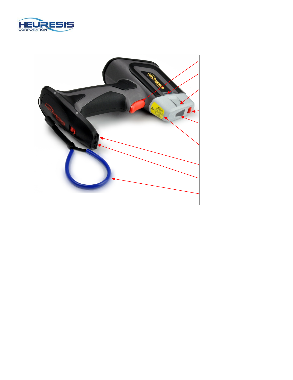
Trigger
Pb200i Features
Figure 1
LED indicator (warning lights)
Active Measurement Area
(for sample)
Proximity button
Snout protector label with
IRTA markings (if applicable)
Instrument label (includes
serial numbers)
Foot stabilizer
Camera
Lanyard
Page 4
Page 4
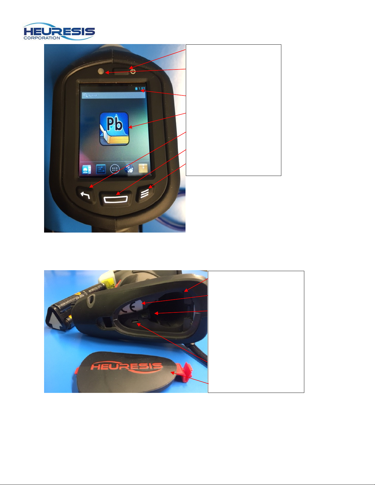
Power On/Off button
Battery door opening
Battery door
LED/Proximity button
indicator
Battery indicator
Pb200i App
Back (Return) button
Home button
Menu button
Figure 2
Figure 3
CE mark
Battery wedge
Caution: removing the
Battery wedge may cause
the battery pack not to fit
correctly.
Mini USB port
Page 5
Page 5
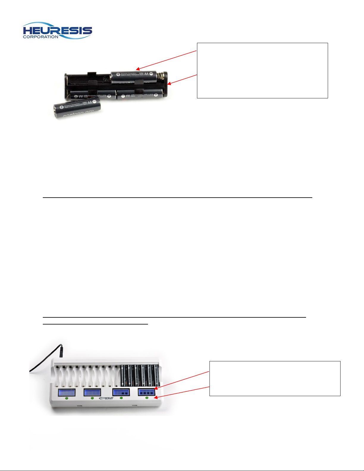
Rechargeable NiMH (Nickel-Metal
Charge indicator
Figure 5
Hydride) or disposable Lithium 6 x AA
cell battery holder
Figure 4
Charging the Batteries
The Pb200i requires 6 AA batteries. Only use rechargeable Nickel-Metal Hydride cells or disposable
Lithium Ion cells (we recommend Energizer Ultimate Lithium).
Caution: Do not use alkaline batteries, as they will not provide the proper power for the system.
1. Identify the positive and negative ends of the batteries and insert them into the smart charger.
Once the batteries are inserted correctly the LCD will turn on as indicated by the black bars in the
charge indicator.
2. The batteries are fully charged when you see 4 solid bars on the LCD display and the lights are
no longer blinking. Fully charging the batteries typically takes 5-6 hours. Cautio n: be sure that
all six batteries are fully charged. If one or more AA batteries are not fully charged, it will
shorten the useful life of the batter y pack .
3. Caution: We recommend using the “Refresh” button on the battery charger at least once every
two to three months. The refresh process typically takes 12 hours. There are four green refresh
buttons, one per each bank of four batteries.
4. Once the batteries are fully charged they are ready for use in the Pb200i. We recommend leaving
the charger plugged in, and the batteries inserted in the charger so that maximum charge is
available for use of the Pb200i. Do not leave batteries in the charger while charger is unplugged,
as they will discharge at an accellerated rate; rather, insert the batteries in the battery holders for
transport or storage.
Caution : Do not mix different manufactu re r’s batteries in the Pb200i battery holder. This may
cause a reduction in your battery life.
Installing the Batteries
LCD display refresh (green button)
Page 6
Page 6
Figure 6
Figure 7
Figure 9
Figure 10
Figure 11
Bottom; this end must be visible
Figure 8
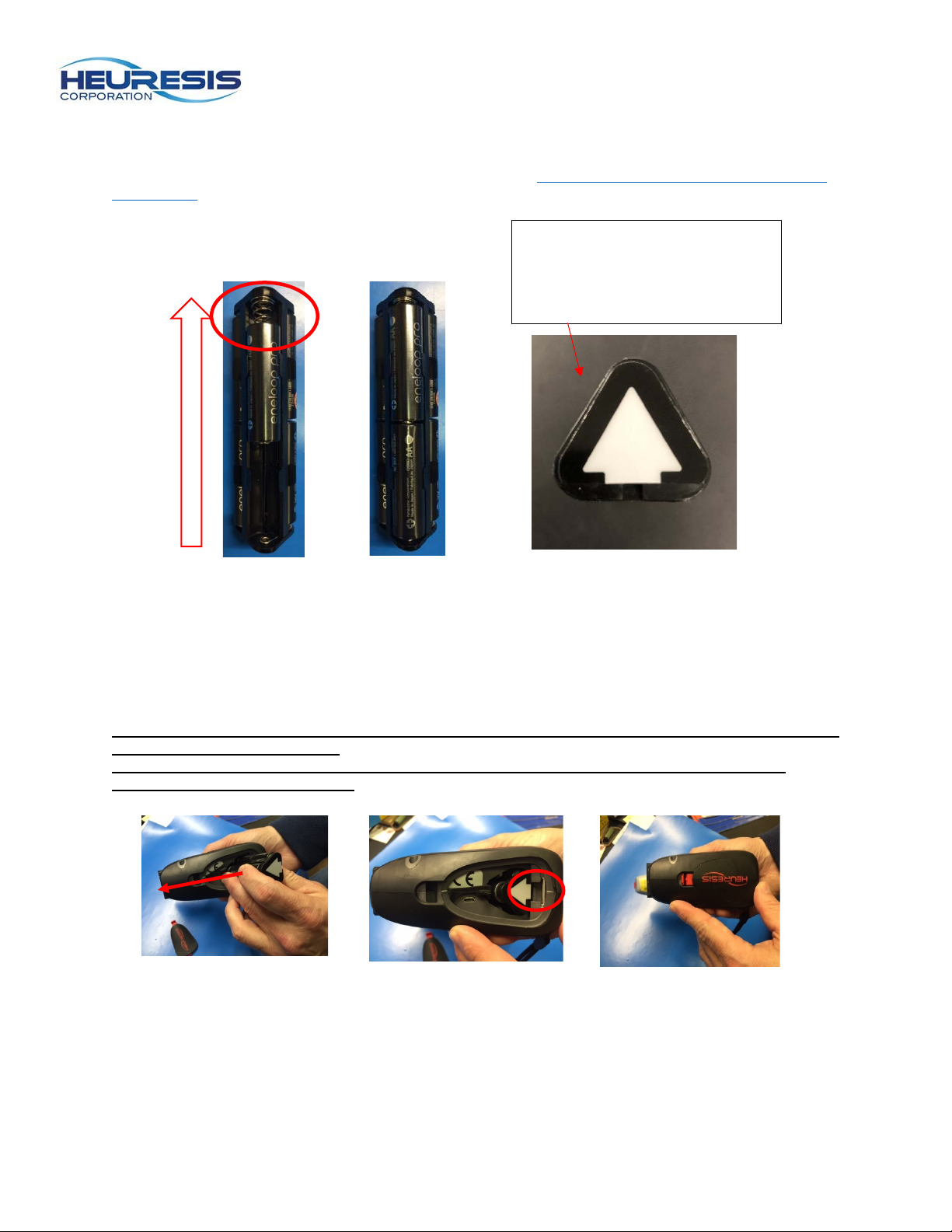
Insert the battery pack with the negative terminal facing the spring, two AA batteries per side, so that all
six chambers of the battery holder are filled (Fig. 6 and 7). Double check that batteries make complete
contact with each other and the springs; adjust as necessary.
the batteries.
Follow this link to watch a video tutorial on
when battery pack is inserted
into your Pb200i.
Remove the battery door on the bottom of the Pb200i. Slide the battery wedge to the side. Insert the
battery holder with the arrow facing the front of the instrument (Fig. 9). Apply slight upward force to seat
the battery holder properly; when fully inserted the battery pack should sit firmly against the battery ledge
(Fig. 10). Secure the battery holder in place with the b attery wedge. Replace the battery door (Fig. 11).
The latching mechanism will click when the battery pack is seated properly.
Caution: Inserting the battery holder with the incorrect orientation will not damage the Pb200i, but
the instrument will not turn on.
Caution: Use care when removing the battery wedge. If broken, your Pb200i will need to be
returned for non-warranty repair.
Page 7
Page 7
Figure 12
Figure 13
Figure 14
Figure 15
Powering On and Initializing the Pb Application Software
1) To power on the instrument, press and hold the Power ON/Off Button until the instrument turns
on.
Caution: The instrument will go to “sleep” after 10 minutes of inactivity. Press any button to
reactivate the instrument.
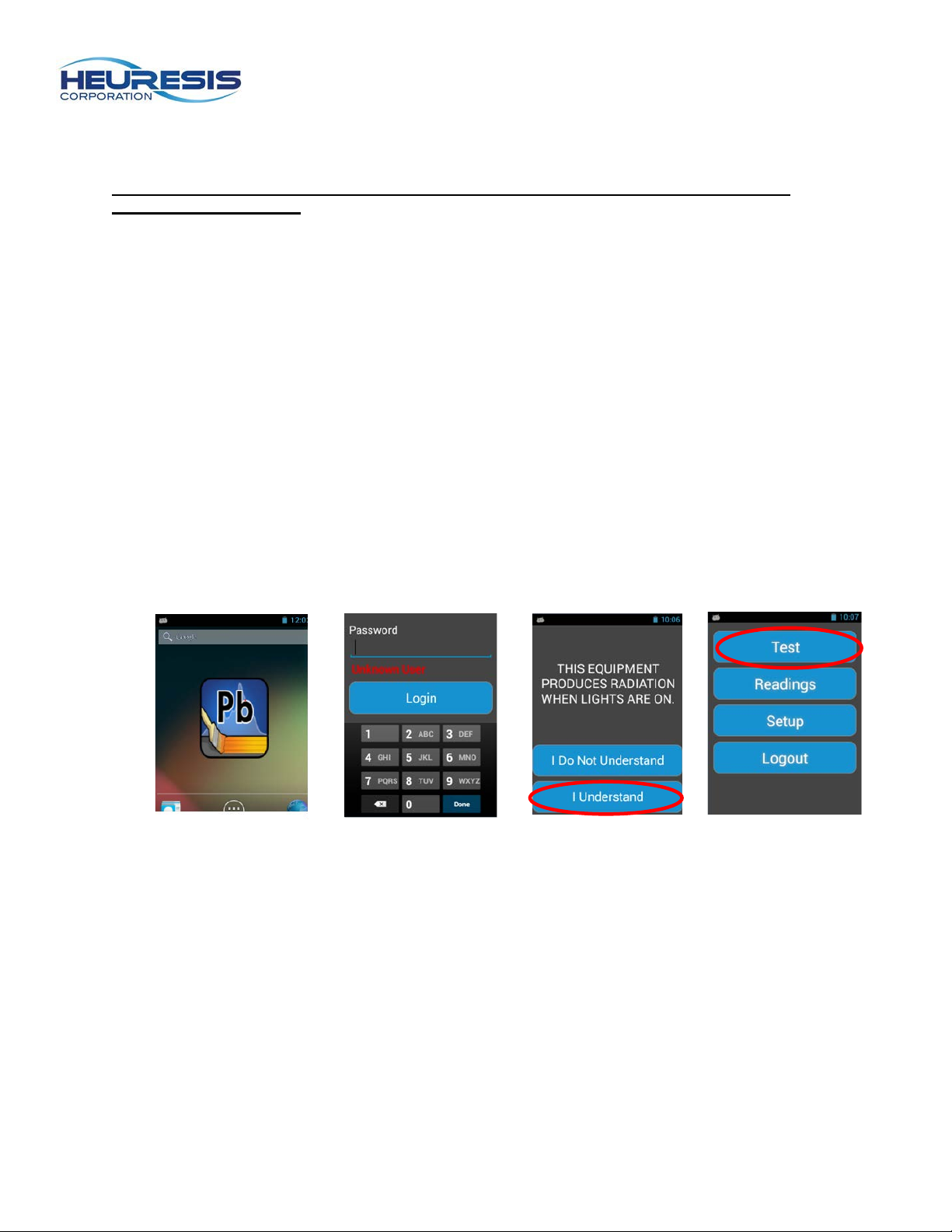
2) Once the Pb200i has completed its boot-up sequence, the LED will turn green and the home
screen will display an Android application showing the “Pb” icon (Fig. 12).
To access the application:
a. Touch the “Pb” icon on the home screen (Fig. 12).
b. On the next screen, enter the password assigned to you by your Compliance or Safety
Officer. Touch “Login” under the “Password” text to activate the keyboard (Fig. 13).
c. Review the Warning Screen and confirm that you understand that the instrument
produces ionizing radiation when the saf ety shutter is open and the warning lights are on
(Fig. 14). If you are not familiar with the radiation safety, please press “I Do Not
Understand” and read the Radiation Safety section in this User Guide before you return
to this screen. If and when you do understand that the instrument produces ionizing
radiation when the safety shutter is open and the warning lights are on, please select the
words “I understand” to proceed to the next screen.
Caution: If you do not fully understand the warn ings on the Warning Screen, please press the
Back button. Do not in proceed before you reread the Radiation Safety section in this User Guide
(see page 45).
d. On the next screen Select “Test” (Fig. 15).
Page 8
Page 8
Figure 16
Taking a Measurement
The Pb application is designed to open and close the safety shutter of the instrument, exposing the
sample in front of the Pb200i measurement window to x-rays and gamma-rays produced by the sealed
radioisotope source in the instrument. The safety shutter can only be opened by pulling the trigger of the
instrument while the proximity button at the top of snout of the Pb200i is fully depressed against a
surface.
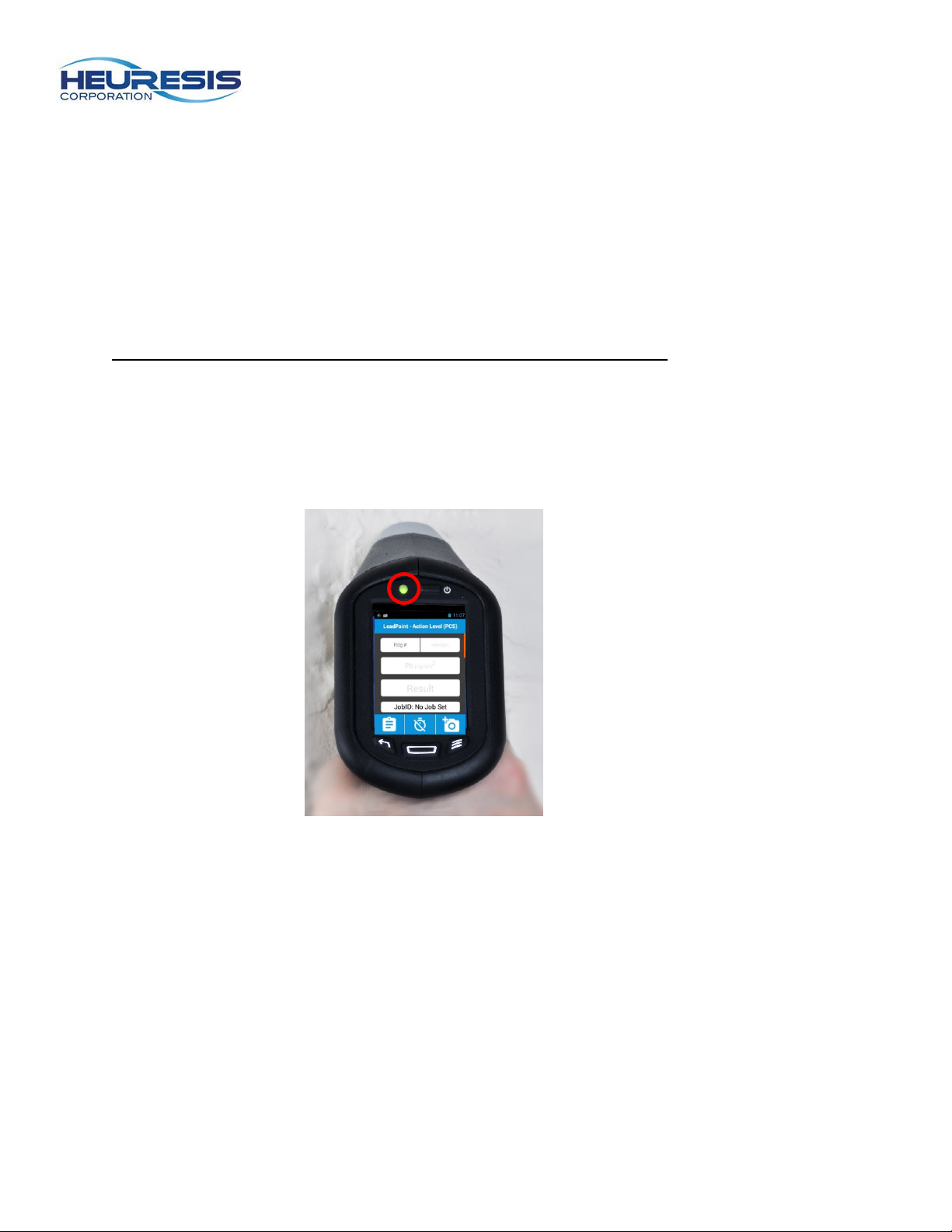
1. To depress the proximity button, place the front of the instrument’s snout flat against the
sample surface. The “Power indicator LED/Proximity button indicator” will turn green when
the proximity button is properly depressed (Fig. 16).
2. Pull the trigger.
Caution: the proximity button must be depressed before pulling the trigger.
When the Pb application is running on the Pb200i and the trigger is pulled with the proximity button
depressed, the shutter will open. The LEDs on the left and right side of the instrument will turn on and
emit red light. The red lights indicate that the shutter is open. If any of the conditions above are not met
during the measurement process, the shutter will close immediately and the red LEDs will shut off. Once
the shutter is open, it will remain open for a maximum of 5 minutes.
Page 9
Page 9
Figure 18
Figure 19
Figure 20
1.04 mg/cm2
Figure 17
Testing the Accuracy and Precision of the Pb200i
The Pb200i should be tested for Quality Control (QC) before each inspection, ever y 4 hours, and whe n the inspection is complete.
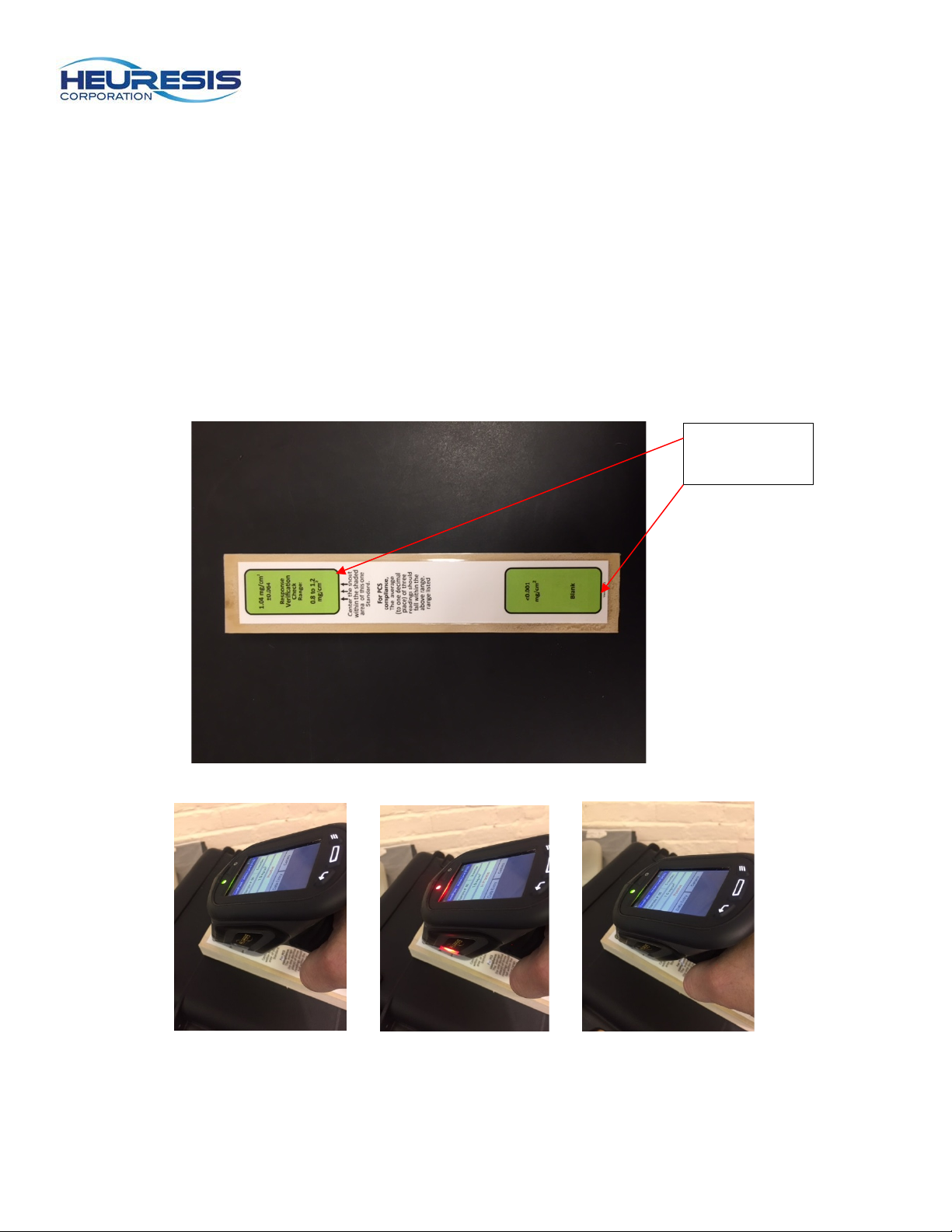
1. Start by placing the wooden reference block (Fig. 17) on top of the Pb200i case. Hold the device
with the proximity button against the wooden reference block, with the snout of the instrument
centered on the paint film nearest 1.0 mg/cm
hold the trigger, keeping the device’s snout in firm contact with the block while continuing to hold
the trigger (Fig. 19). The reading will automatically terminate (Fig. 20) when the device has
determined whether the sample is classified as Positive (when Pb≥1.0 mg/cm
(when Pb<1.0 mg/cm
2. Compare the result to the value on the reference block and make a note of the reading.
3. Complete the test 3 times, then average the readings. The average (rounded to 1 decimal place)
of the three readings must fall between 0.8 and 1.2 mg/cm
QC check in accordance with the Performance Characteristic Sheet (PCS).
2
).
2
. When the LED turns green (Fig. 18), squeeze and
2
), or Negative
2
(inclusive) for the Pb200i to pass its
Blank
Page 10
Page 10
Result
Action Level indicates “Positive”
determination could be made.
Measurement reading
seconds
Reading/sample
number
If your instrument is
Negative.
Figure 21
Figure 22
Performing an Inspection with the Pb200i
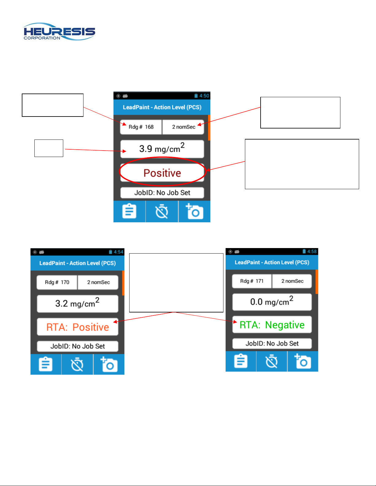
Pressing the trigger initiate s the measurement. As the reading is taken, you will see the results on the
screen change to reflect the measurement data (Fig. 21 and 22).
time in nominal
or “Negative” result. “NULL”
indicates the reading was
terminated before a
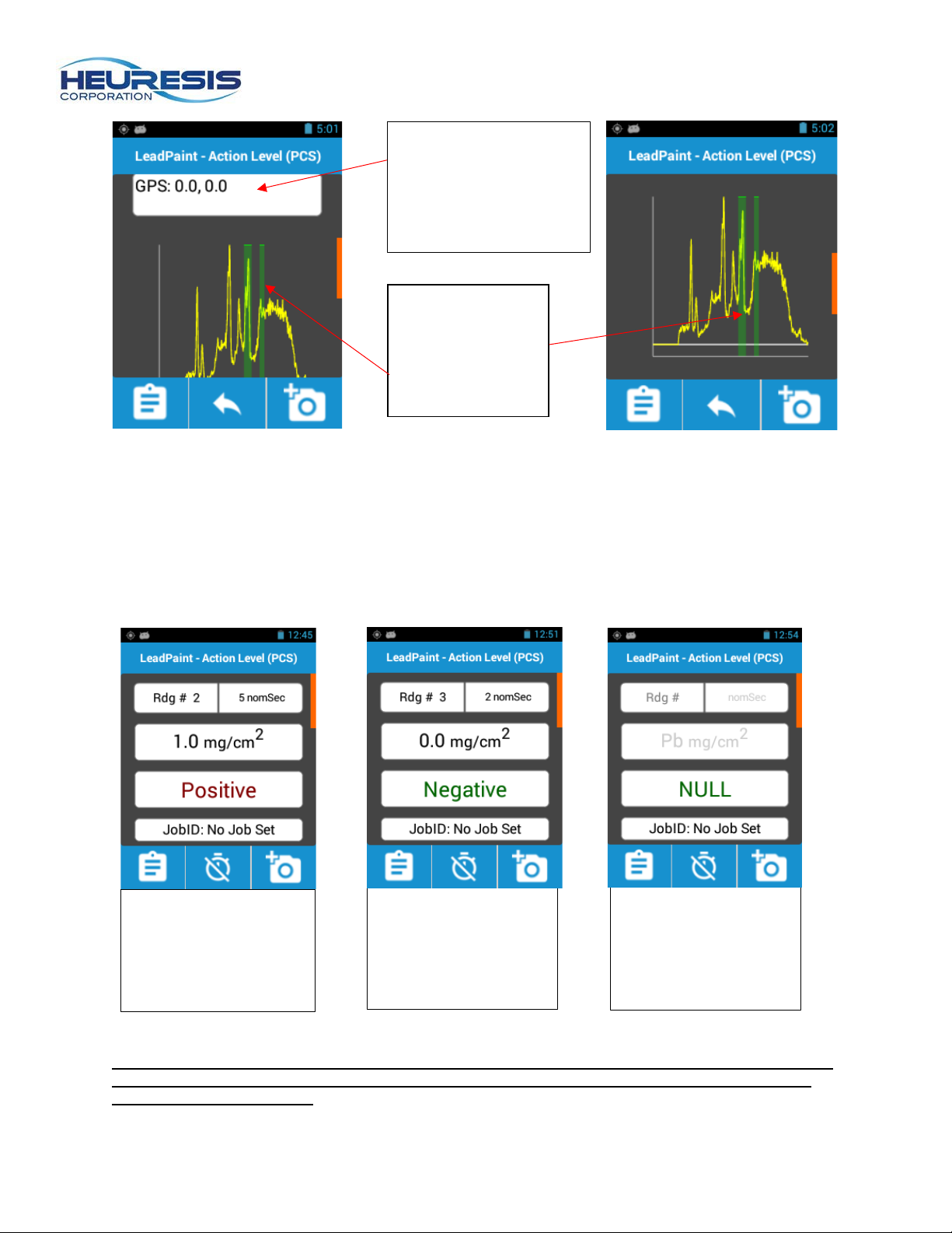
Once the reading is recorded, scrolling from the bottom up will allow the user to view the GPS
coordinates (Fig. 23) and spectrum of the reading taken (Fig. 24).
equipped with the internal
read through adaptor
(iRTA), it will display either
RTA: Positive or RTA:
Page 11
Page 11
Green vertical
GPS Coordinates
Figure 27
“Null” – Reading was
readings are not valid.
Figure 26
“Negative” – lead
Figure 25
“Positive” – lead
Figure 23
Figure 24
(shown as 0.0, 0.0 as
the Pb200i was not
connected to satellites
during the reading)
bars indicate lead
Kα and Kβ peaks
Scroll bar
Once the measurement is determined to be Positive or Negative, the shutter will close, the warning LEDs
will turn off and the result will be displayed and saved.
Typical measurement times in Action Level (PCS) Mode take 1 to 3 nominal seconds; the closer the
measured value is to the action level, the longer the testing time will be. The maximum measurement time
in Action Level mode is five nominal seconds without iRTA and ten nominal seconds with iRTA. The
results shown in the examples in Figure 25, 26, and 27 are based on an action level of 1.0 mg/cm
present. Result at or
above the selected
Action Level.
Caution: The Action Level can be changed on the Pb200i by a user with administrative rights, but
the Pb200i’s Performance Characteristic Sheet (PCS) only pertains to lead inspections with an
Action Level of 1.0 mg/cm2. [This is true for all XRF lead paint analyzers with a PCS.]
below selected Action
Level.
terminated before the
instrument had made a
Positive or Negative
determination. NULL
2
.
Page 12
Page 12
Figure 28
Figure 29
Figure 30
Figure 32
Figure 31
Using the Internal Read Through Adaper (IRTA)
For instruments equipped with the optional internal read through adapter (iRTA), this next section will
guide you on it’s proper use. Instruments equipped with an int er na l read through adapter will have a front
sticker as shown in Fig. 28, and a black snout; instruments without the iRTA will have a silver snout (Fig.
1).
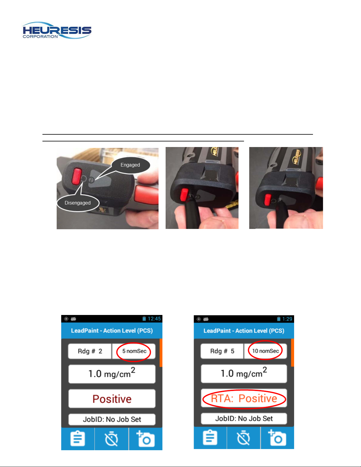
The iRTA has “on” and “off” positions that are set by using a magnetic stylus to slide it between positions
as seen in Fig. 29 and 30. In Fig. 29, the empty circle on the sticker denotes the “off” position. Fig. 30, the
filled circle with the letters “RT” denotes the “on” position.
Caution: The magnet on the stylus should always be sitting on the top of either circle in the “on”
or “off” position to ensure that the iRTA is fully engaged or disengaged.
Take a measurement in Action Level mode with the iRTA in the “off” (disengaged) position as seen in
Fig. 29. If there is lead in the sample which concentration falls w ith in +/- 20% of the action level, the unit
will take a 5 second measurement. (Fig. 31) If the reading is outside of +/- 20% of the action level, the
Pb200i will complete the measurement in 1-2 seconds.
Take a measurement in test mode with the IRTA in the “on” position as seen in Fig. 30. If there is surface
lead in the sample within +/- 20% of the action level, the unit will take a 10 second measurement. You will
see an indicator on the disp lay that the iRTA is present (engaged) as shown in Fig. 32. If the reading is
outside of +/- 20% of the action level, the Pb200i will complete the measurement in 1-2 seconds.
Page 13
Page 13
Figure 34
Figure 33
Data Entry Fields
HUD Chapter 7, Section IV. B. 3 requires that lead inspectors document their XRF reading locations,
including room (or room equivalent), side, and building components; additional requirements of Chapter 7
call for the recording of substrates, calibration check readings, and other details associated with the
inspection. Clients may ask for additional details, such as color, paint condition and cause (if the paint is
deteriorated), or other parameters.
The Data Entry function on the Pb200i is a powerful recording tool designed to help the inspector
expedite the documentation process, such that the inspector can become more efficient recording the
details required for their inspection work.
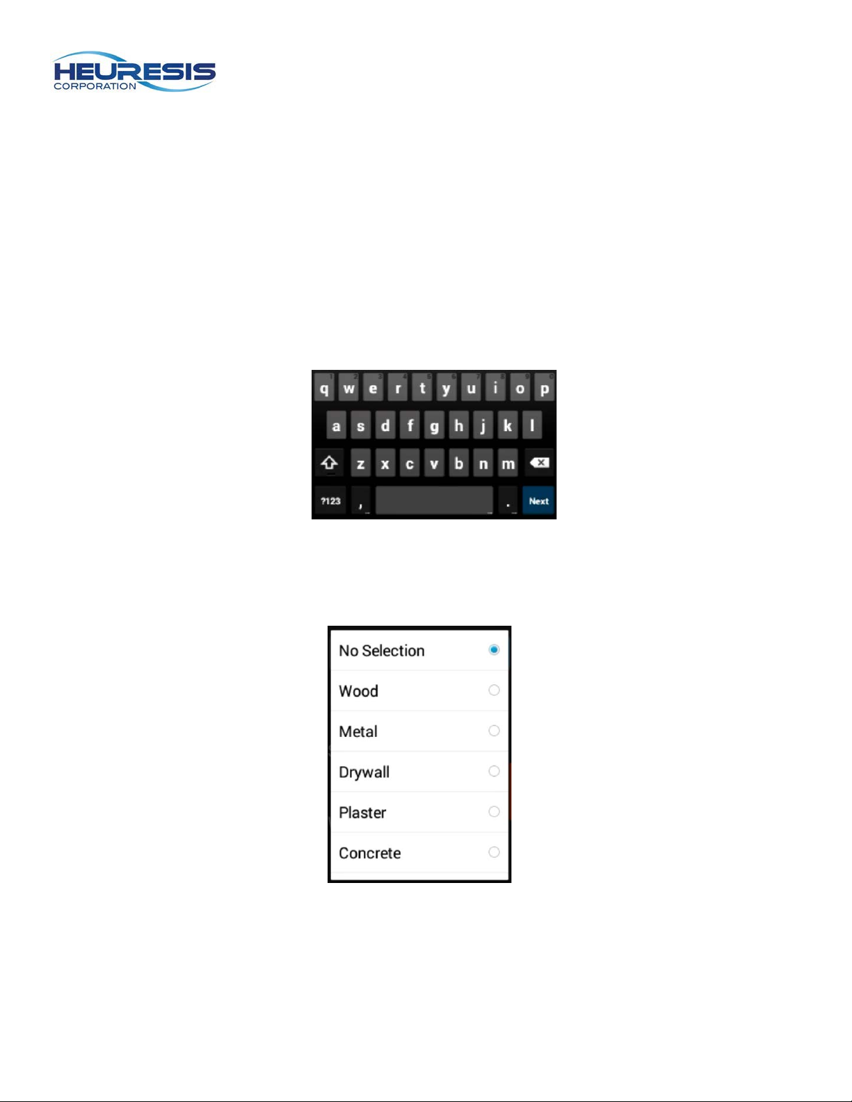
Data fields can be classified in one of three ways:
Alphanumeric: The inspector can enter inspection details using a virtual “qwerty” keyboard, as shown in
Fig. 33.
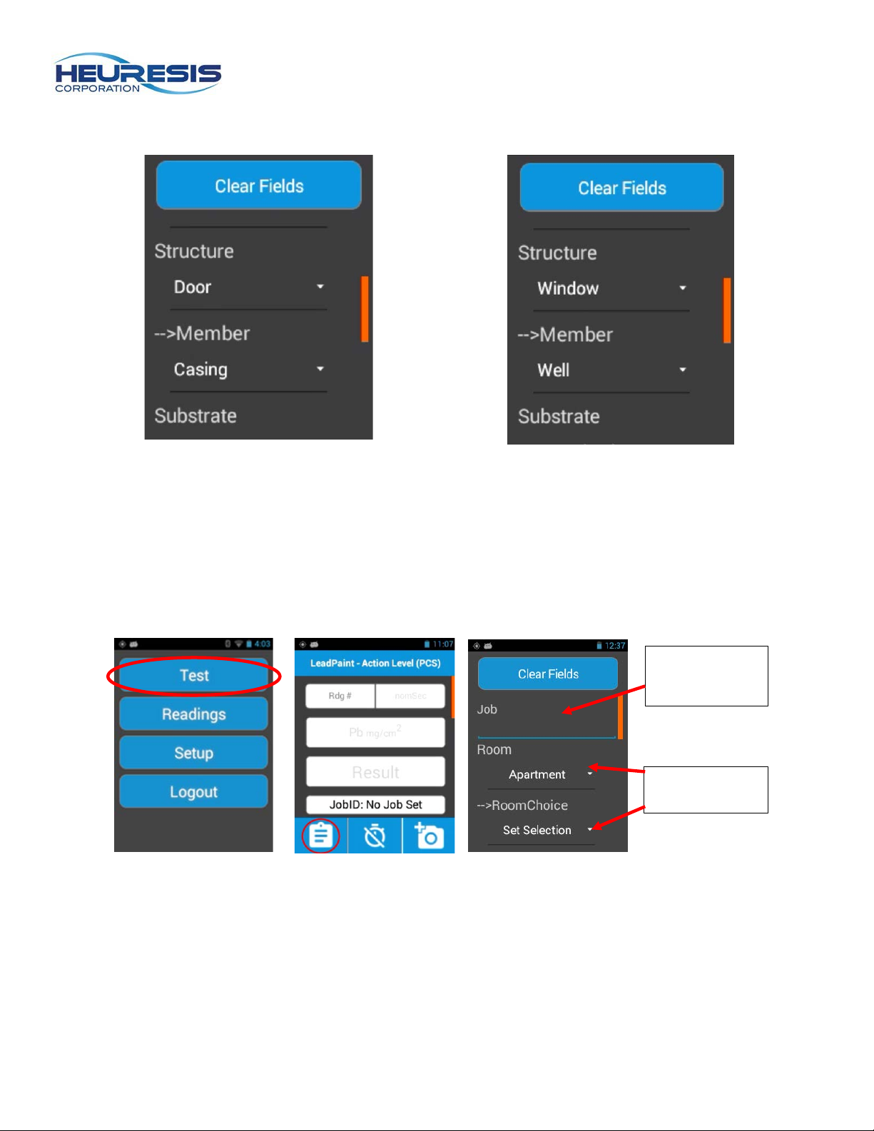
Standard Picklist: The inspector choses an entry from a single list of choices, as shown in Fig 34.
Page 14
Page 14
Alphanumeric
Figure 35
Figure 36
SmartFields™
SmartField™: A set of contingent data fields, where selection of a primary field returns a different set of
results for a secondary field (Fig. 35 and 36).
Your Pb200i is equipped with a default set of data entry fields.
The data entry fields are completely customizable for the Pb200i. Please see the HDMS User Guide,
software version 3.2 or later for additional details.
To use data entry, select Test (Fig. 37), then tap the clipboard icon (Fig. 38). Fig. 39 shows an
alphanumeric data entry field, and a SmartField.
field
Figure 37 Figure 38 Figure 39
Once you have selected/entered the appropriate data entry fields for your next measurement, you may
initiate the reading from the data entry screen; there is no need to return to the test screen (Fig. 38)
before proceeding.
Page 15
Page 15
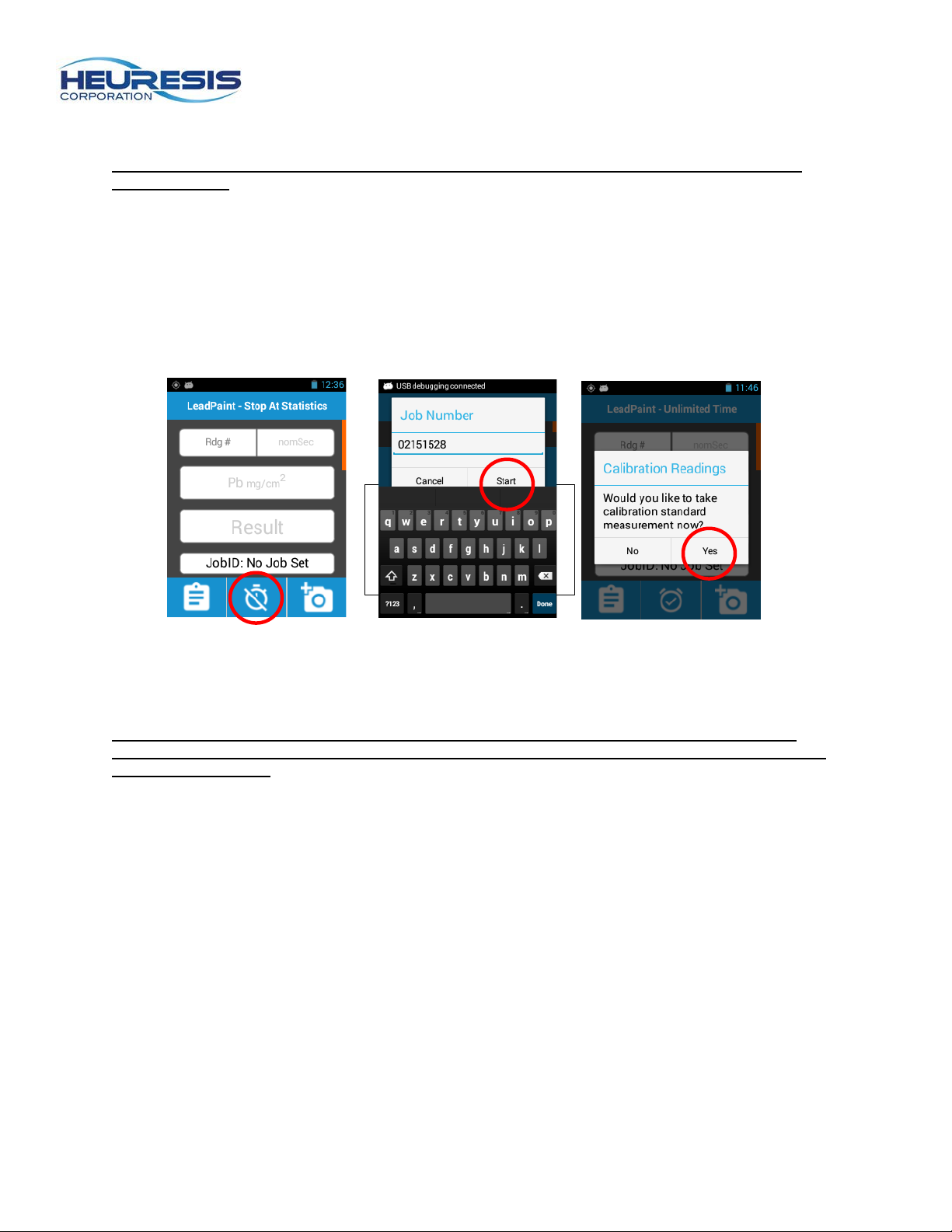
Select New Job
Perform three (3)
The Pb200i will
Figure 40 Figure 41 Figure 42
Creating a Job and Performing a Calibration Check
Caution: Make sure that the Action Level is set to 1.0 mg/cm2 before beginning the calibration
check readings.
Using Job Numbers is an effective way for inspectors to segregate their different lead inspections, helping
them to generate reports in less time, with less effort that previously possible with a handheld XRF
analyzer.
Begin by selecting the New Job icon (Fig. 40). Accept the date/time-based entry which autom atic al l y
populates in the Job Number field, or enter your own Job Number or inspection address, and select Start
(Fig. 41). Select “Yes” to have your Pb200i prompt you through the calibration check readings (Figure
42).
readings on the
lead 1.0 standard.
automatically calculate
the average of the three
readings.
Place the calibration test block on top of the black “Pelican” XRF case as shown in Fig. 17 for all
calibration check readings. Make sure the RTA is OFF (disengaged) for all calibration check readings.
Caution: Failure to properly position the Pb200i on it’s supplied calibration test block, and or
failure to place the test block on the black Pelican carrying case may cause the instrument to fail
the calibration check.
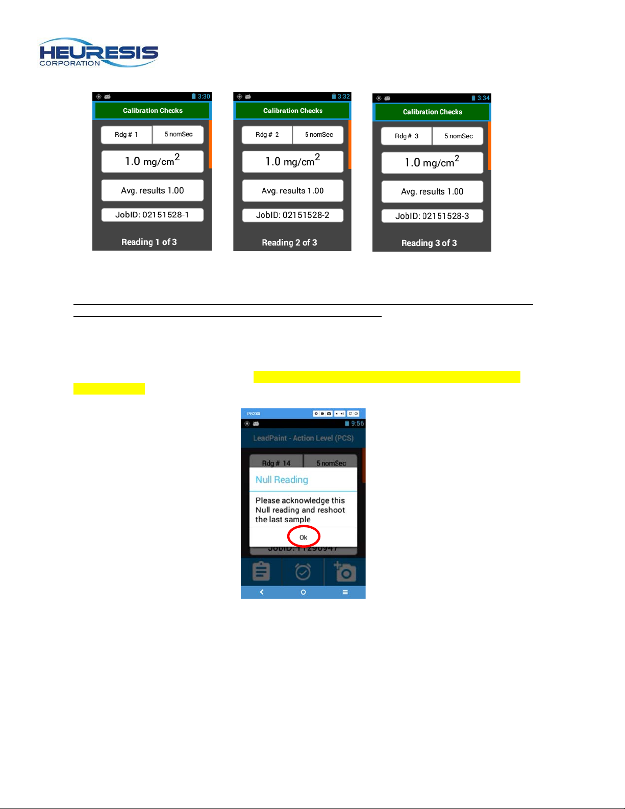
Perform three measurements on the reference sample closest to the 1.0 mg/cm
average of these three readings (rounded to one decimal place) falls between 0.8 and 1.2 mg/cm
Pb200i is considered “in control”. Note that the JobID increments to track the number of readings in the
job, as shown in Fig. 43-45. Repeat the process on the blank reference sample.
2
action level; if the
2
, yo ur
Page 16
Page 16
Figure 43
Figure 44
Figure 45
Figure 46
Note: While measurements on the blank are not required for compliance with the PCS, they are
necessary for workflow associated with the JobID fun ctionality.
Null Readings
Null readings, where the Pb200i did not complete it’s Positive/Negative determination must be
acknowledged on the display (Fig. 46). To disable this functionality, please see the section on Test
Screen Display.
Page 17
Page 17
Figure 47
Figure 48
Figure 49
Figure 50
Deleting Last Reading
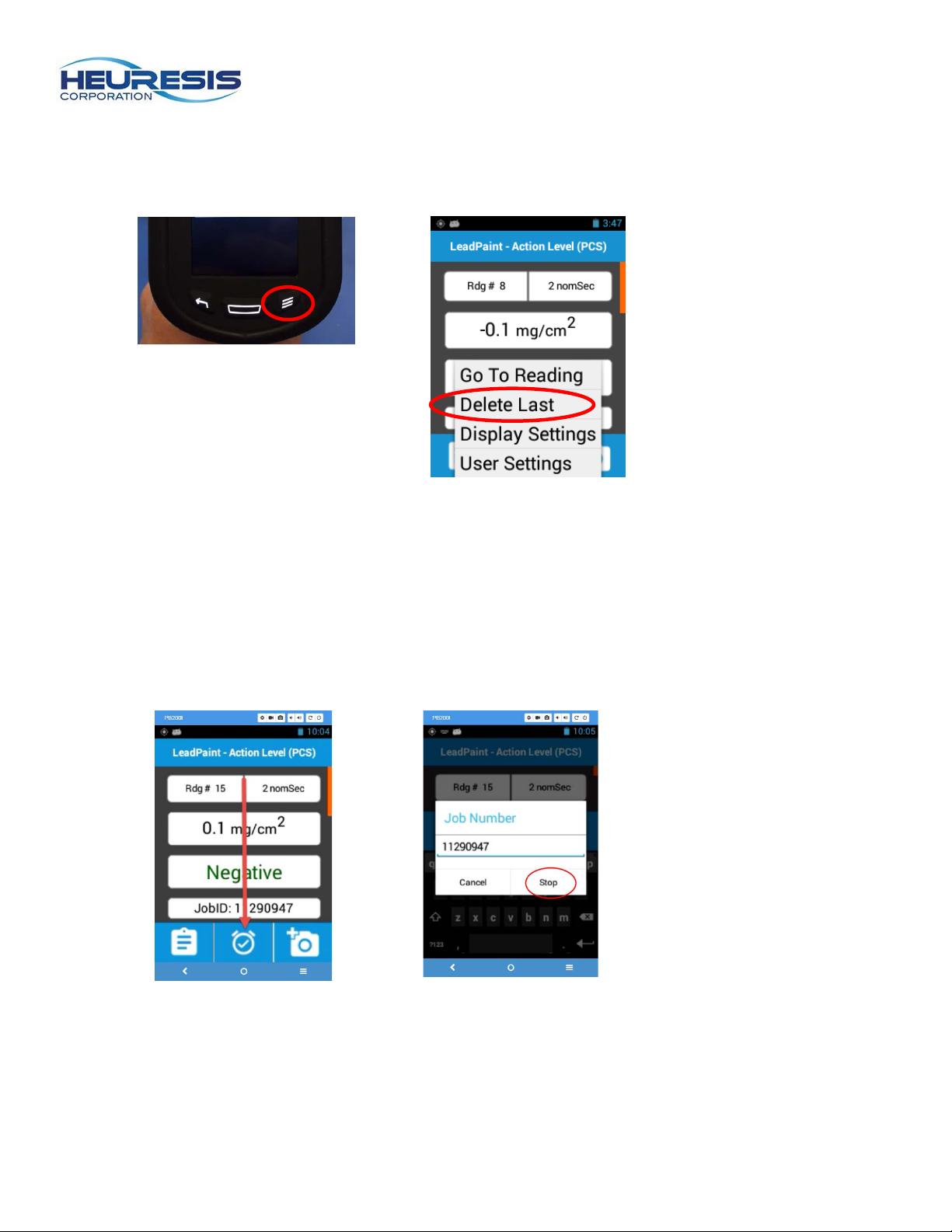
To delete the last reading, select the Menu button (Fig. 47) and “Delete Last” (Fig 48).
Stopping a Job
Select the “Job” icon to stop the current job (Fig. 49). Follow the Calibration Check prompts on the
display after stopping the job (Fig. 50) .
Page 18
Page 18
Figure 53
Figure 54
Figure 51
Figure 52
Retrieving Data
Your Pb200i is capable of providing you with your inspection data in two formats: a .CSV file, which may
be opened in Microsoft Excel® or other spreadsheet programs; and HDMS (Heuresis Data Management
Software), which stores the data in a tamperproof file format. To learn more about using HDMS, please
see the HDMS User Guide.
To retrieve data, begin at the “Main Screen” (Fig. 15). You may access the main screen from any other
screen on your Pb200i by pressing the Back (Return) button until you get to the Main Screen.
Caution: Always export data before connecting the Pb200i to your PC. If you connect your PC
prior to exporting readings, you may not retrieve the entire data set.
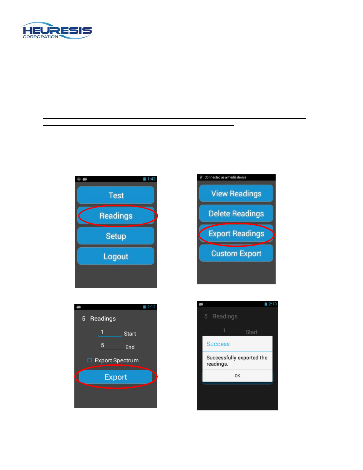
On the main menu, select “Readings” (Fig. 51) then “Export Readings (Fig. 52). Select the range of
readings you wish to include in the export (Fig. 53), and whether or not you wish to be able to graph the
x-ray spectrum from this range of readings. Select Export. To learn more about graphing the x-ray
spectrum for a reading, or range of readings, please view the help menu for your spreadsheet software.
Page 19
Page 19
Figure 55
Caution: Checking the Export Spectrum box will include two additional lines of data
associated with each reading. The Export Spectrum feature is turned off by default.
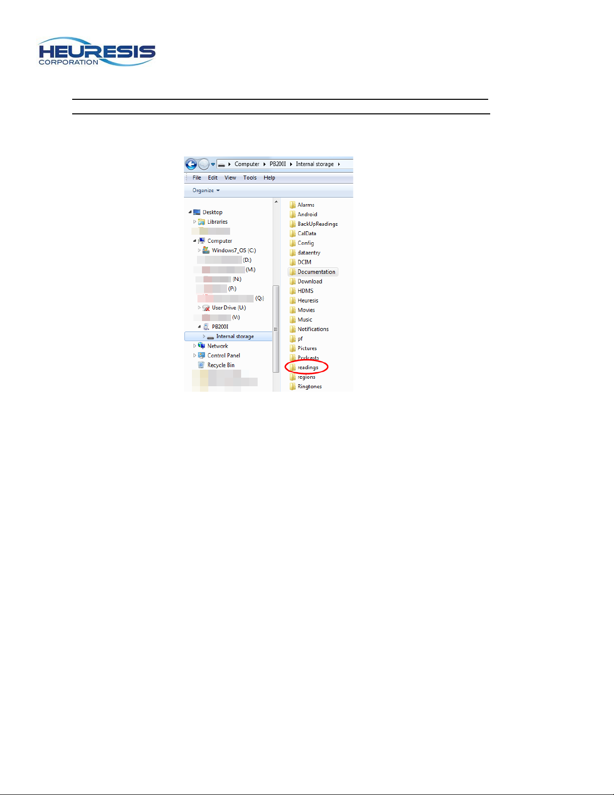
The data is “exported” to a “Readings” directory folder (Fig. 55).
Page 20
Page 20
Figure 56
Figure 57
Figure 58
Figure 59
Transferring Data
You can transfer data to your PC via the supplied mini USB cable.
Using the USB Cable
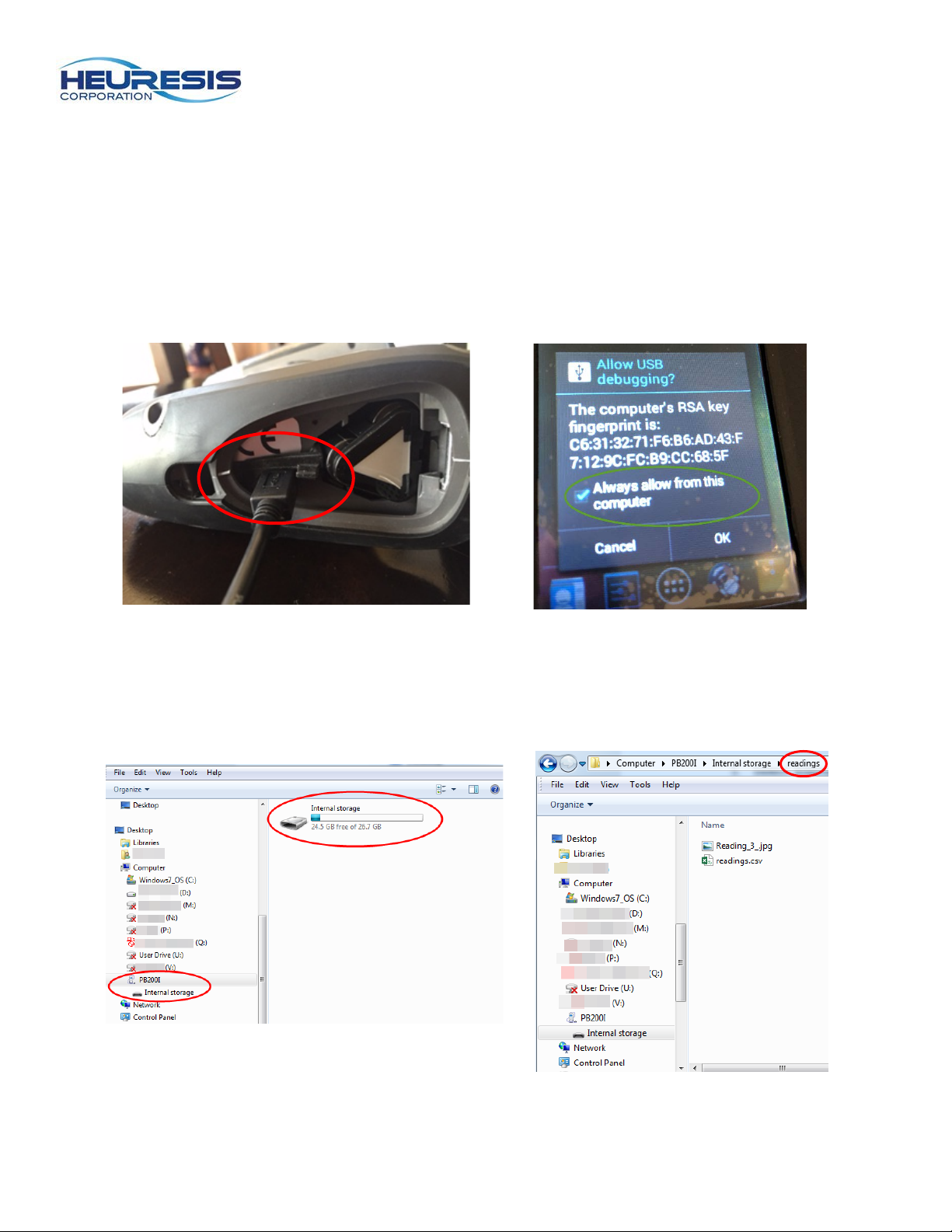
To use the mini USB cable, start by removing the battery door. Insert the USB cable, making sure the
battery wedge remains in place (Fig. 56). Be sure to use the cable supplied with your Pb200i.
Connect the USB cable to the PC. The driver will install automatically. You may also get a message on
your Pb200i that reads “Allow USB debugging?” the first time you connect to your PC (Fig. 57). Select
“Always allow from this computer” and then select “OK.” When connecting the Pb200i to a PC, it will
appear as though you’ve plugged in an external drive (Fig. 58). Select internal storage, then select the
“Readings” folder (Fig. 55).
Page 21
Page 21
Figure 60
Figure 61
Figure 62
Figure 63
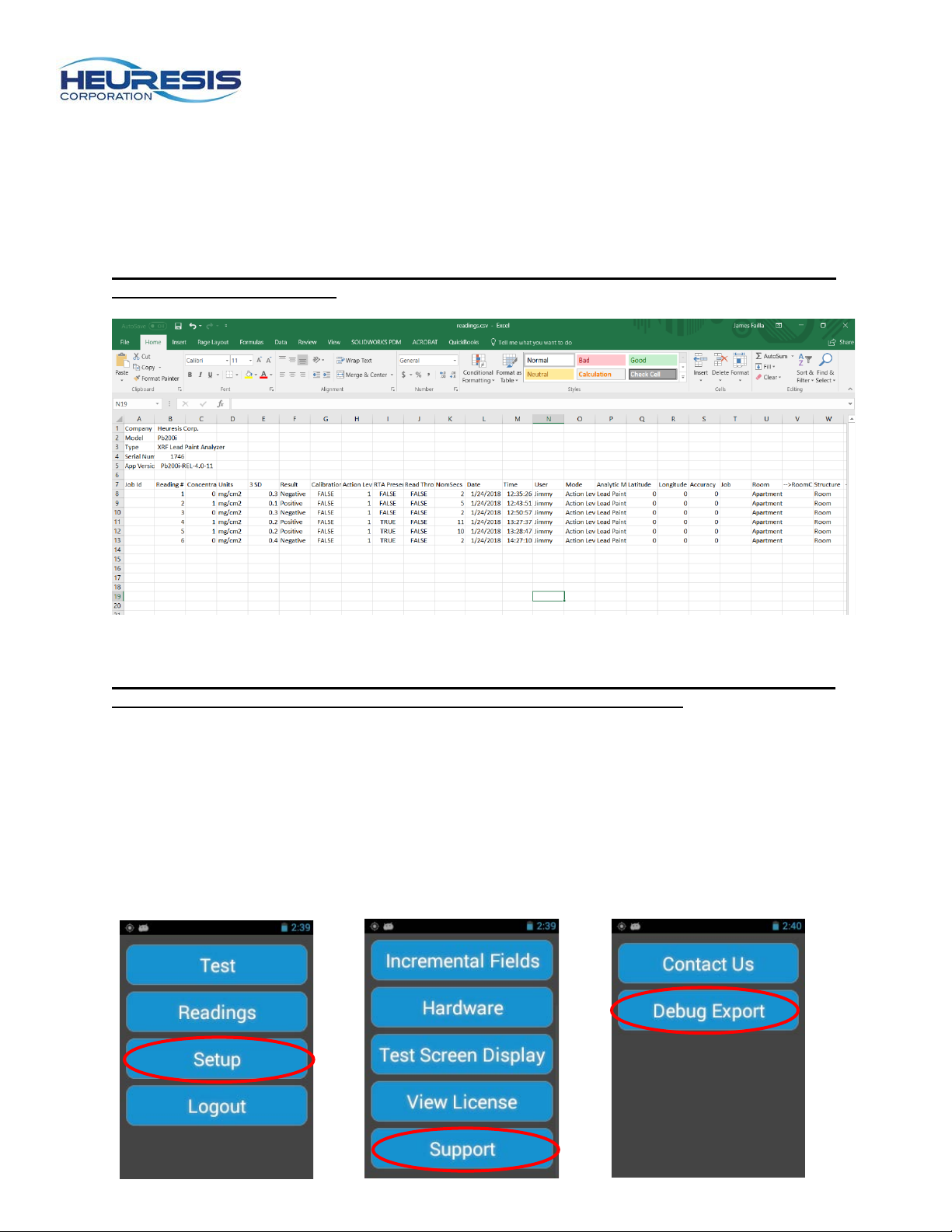
Once you select the readings file you will see a readings.csv file (Fig. 59), as well as image files for any
photos taken with your Pb200i that were ass ociate d w ith read in gs . The readings.csv file contains your
readings, while the image files are named to associate them with individual readings. The example shown
in Fig. 59 has a photo associated with reading 3. Copy the file(s) to your desktop (or other location on
your PC), and select the file(s) to open. Fig. 70 shows a .csv file that has been opened in Microsoft
Excel®.
Caution: Do not attempt to open the .csv or .jpg files on your Pb200i; copy them to your PC before
attempting to open these files.
Caution: Check to make sure that all of the data intended for export is included in the download. If
it is not, unplug the analyzer from the USB cable, and repeat the steps above.
You may also use Heuresis HDMS software to retrieve the readings from your Pb200i in a tamperproof
format; retrieve your previo us l y exporte d .csv file; customize the order and content of exported .csv files;
and to create reports. Please see the HDMS User Guide for instructions, located on the analyzer in the
“HDMS” folder.
Downloading Debug Data
In certain situations you may be asked by Heuresis Tech Support to download debug readings. This is generally used for troubleshooting purposes for the Pb200i. Select the following: Setup > Support> Debug Export. (Fig. 61 through 63).
Page 22
Page 22
Figure 65
Figure 64
Figure 66
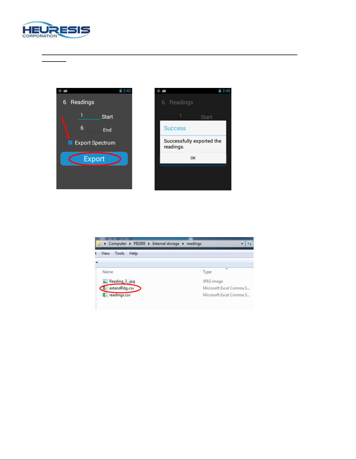
Caution: Ensure that the USB cable is NOT plugged in until readings have been successfully exported.
Leaving “Export Spectrum” checked, select “Export” (Fig. 64). Your Pb200i will tell you if it has successfully exported the readings (Fig. 65). Select OK.
To retrive the debug readings, repeat the process described in “Transferring the Data” to retrieve the
extendRdg.csv. The readings will be in the same “Readings” file location (Fig. 66).
Page 23
Page 23
Figure 67
Figure 68
Figure 69
Figure 70
Using Wi-Fi Connectivity
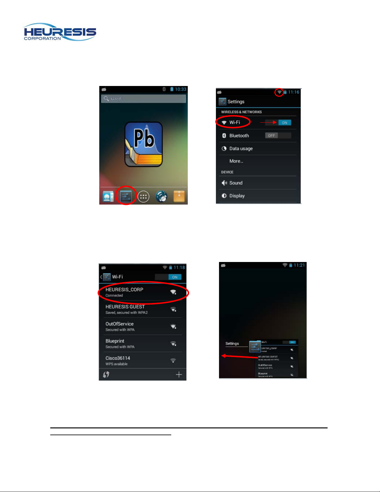
You can also use Wi-Fi to transfer your data via an FTP client. To enable Wi-Fi usage, select the
“Settings” icon (Fig. 67). Enable Wi-Fi by swiping right; the “Wi-Fi” icon will appear (Fig. 68).
After enabling Wi-Fi, tap on the word “Wi-Fi” as circled in Fig. 68. Find the desired network, select and
connect (Fig. 69). Enter any required Wi-Fi password to proceed.
Exit from Wi-Fi using the left arrow, then close the “settings” app by holding the center “Home” button
down until a list of open apps appears (Figure 70). Swipe left to close the Settings app.
Caution: Turning on Wi-Fi will decrease the battery life of the Pb200i. We recommend leaving
the Wi-Fi feature off when it is not in use.
Page 24
Page 24
Figure 71
Figure 72
Figure 73
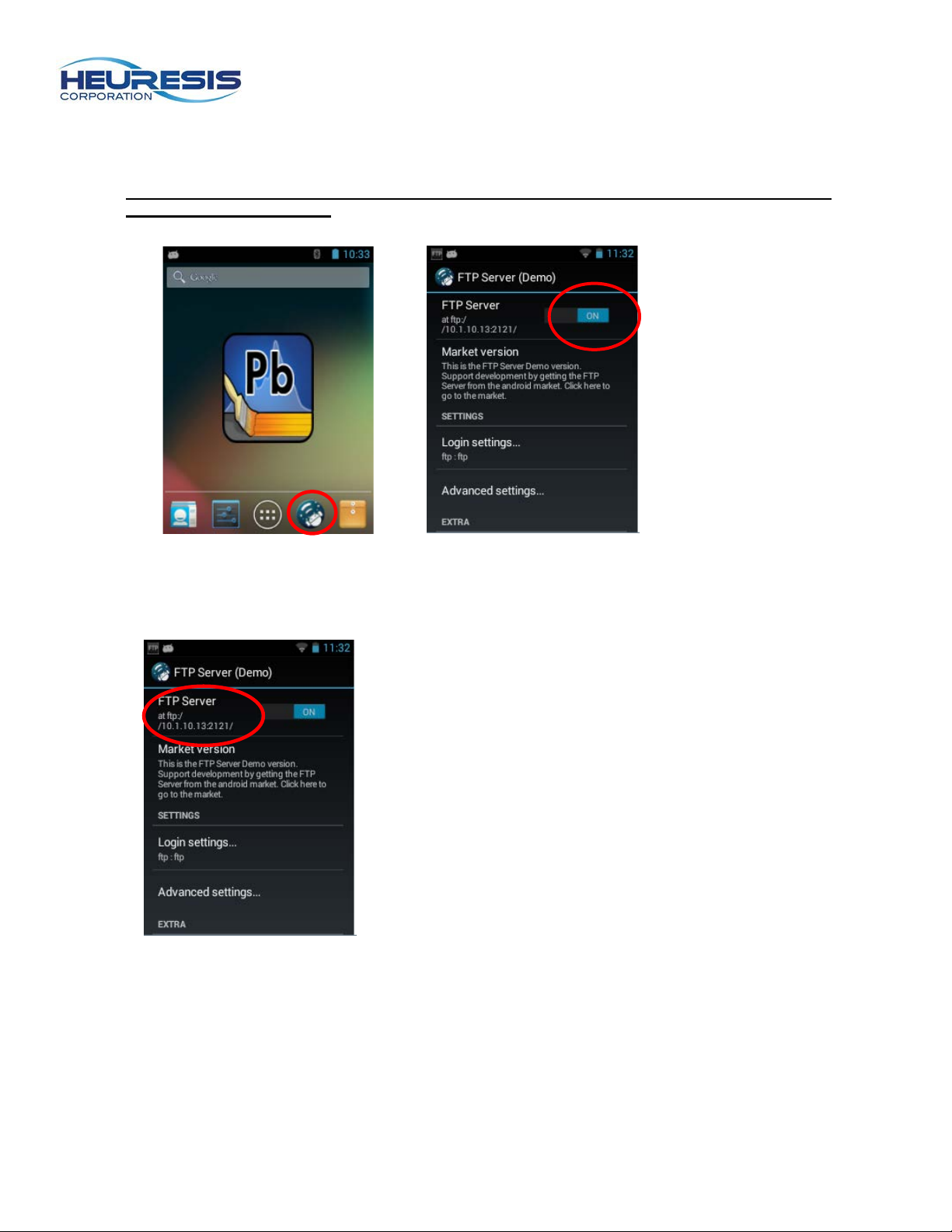
Select and open the FTP Server app (Fig. 71). To enable the FTP server, select the icon and swipe
from off to on (Fig. 72).
Caution: The FTP server feature will default to the “off” position for security reasons every time
the instrument is turned on.
Place the number which appears in the area circled in Fig. 73 in your web browser. The example shown
here is ftp://10.1.10.13:2121/
Page 25
Page 25
Figure 74
Figure 75
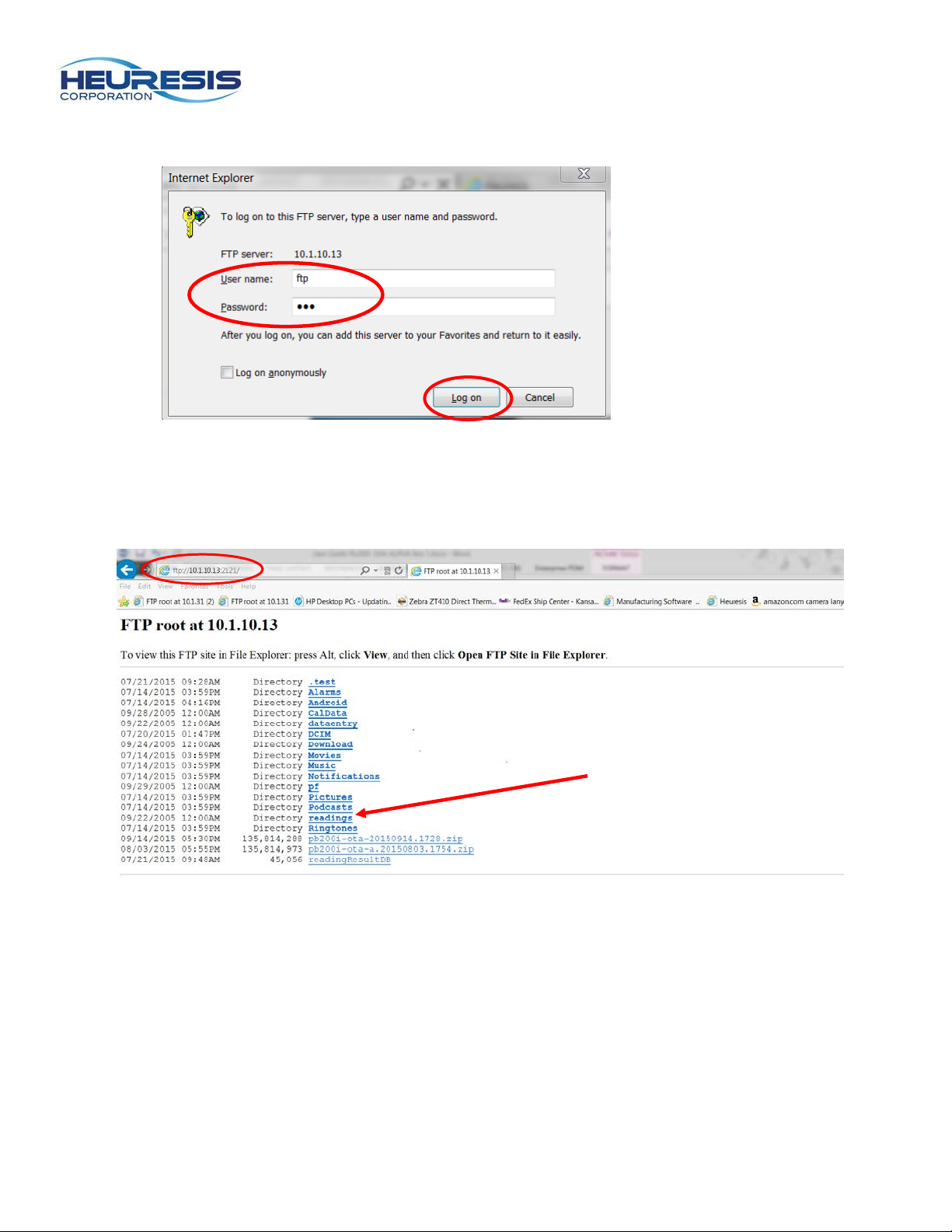
Your browser be prom pt you to enter a user name and password (Fig. 74). Enter “ftp” as the User name
and “ftp” as the Password. Select “Log on”.
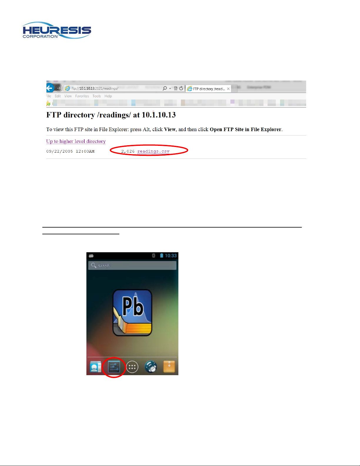
Your screen should display the file tree located on your Pb200i as shown in Fig. 75. Be sure to bookmark
this page in your browser. Select the “readings” folder.
Page 26
Page 26
Figure 76
Figure 77
At this next screen (Fig. 76) select “readings.csv” You will be prompted to save the readings in a location
of your choice (.csv file format). You may also retrieve any photos taken which are associated with the
exported readings.
Enabling Bluetooth™ Connectivity
The Pb200i is equipped with a Bluetooth™ radio. You can use this feature to pair the instrument to an
external keyboard or other Bluetooth™ device.
Caution: There are multiple Bluetooth™-equipped devices on the market, but they are not all
compatible with the Pb200i.
To enable Bluetooth™, select the “Settings” icon (Fig. 77).
Page 27
Page 27
Figure 78
Figure 79
Figure 80
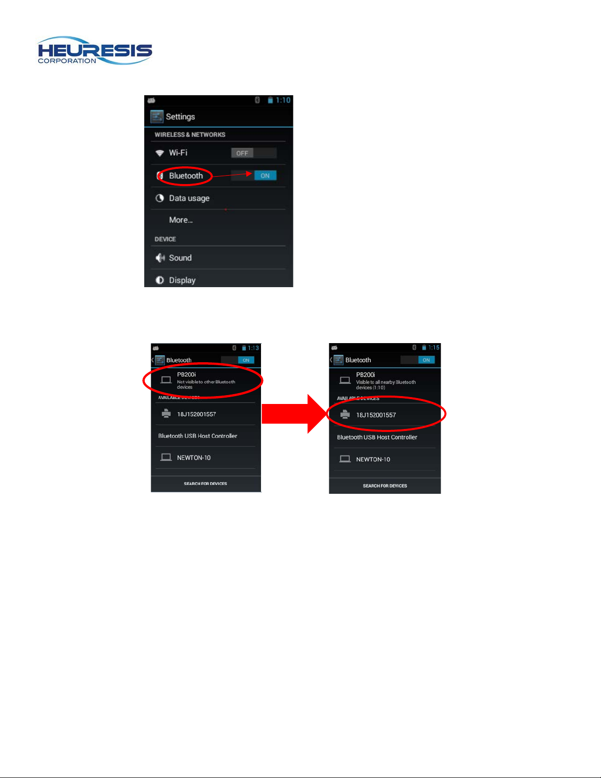
Enable Bluetooth by swiping right; click on “Bluetooth” (Fig. 78).
A list of available devices will populate on the screen; click on the Pb200i (Fig. 79). This makes the
instrument visible to other devices. Click on the desired device to pair it with your Pb200i (Fig. 80).
Page 28
Page 28
Figure 81
Figure 82
Figure 83
Figure 84
Turning On the GPS Receiver
The Pb200i is equipped with an onboard GPS receiver, which is set to “On” by default at the factory.
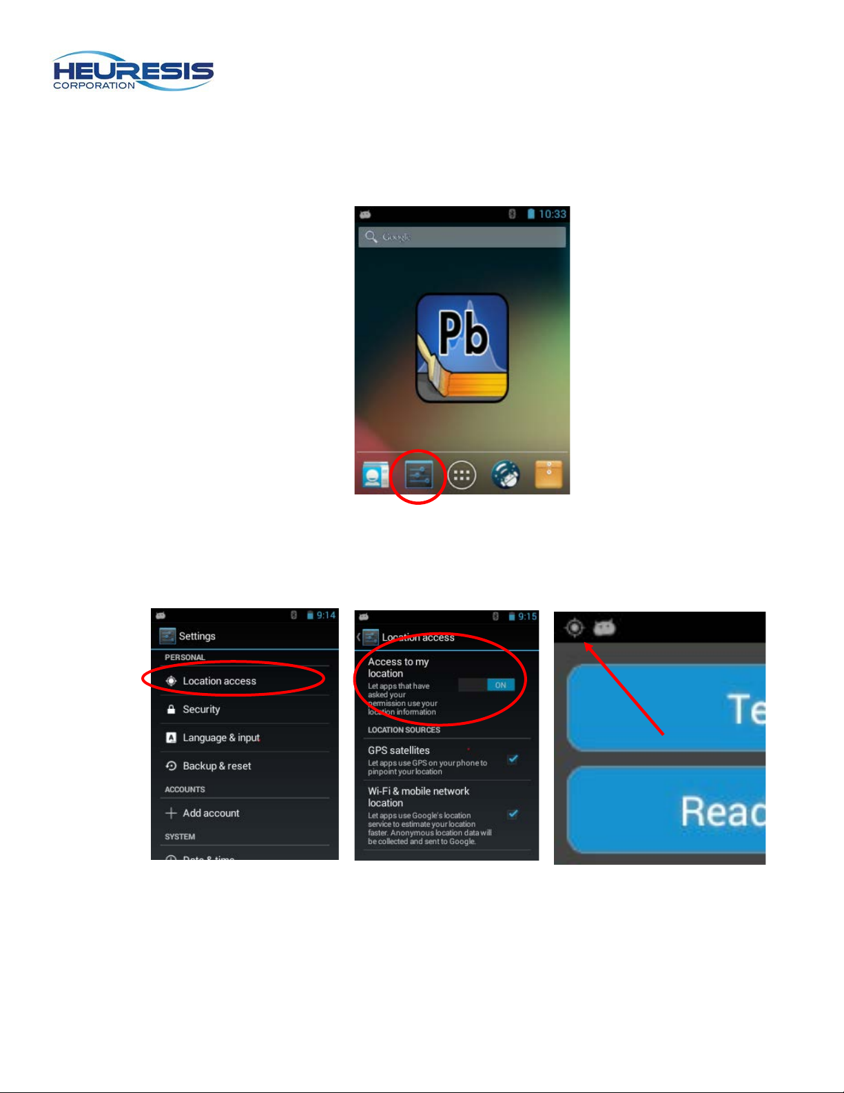
Follow these steps to turn on/off the GPS receiver. Select the “Settings” icon (Fig. 81).
Scroll down to “Location Access” (Fig. 82) and select. Slide “Access to my location” to “ON” (Fig. 83). The icon in shown in Figure 84 will appear when GPS is enabled.
Page 29
Page 29
Figure 85
Figure 86
Figure 87
Figure 88
371945
Figure 89
Figure 90
New name and
password
Figure 91
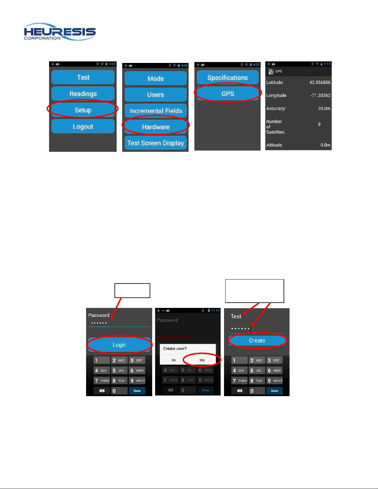
To check the status of your GPS, go to the following screens Setup>Hardware>GPS (Fig. 85-88).
Creating an Administrator
When first logging on to the Pb200i, you will need to create a username and password. Start by using the
factory default password: 371945.
You will be prompted to create the first user. This person will be the device administrator, and can
administer rights to other users as needed. This person should be a high-level em ployee, responsible for
the instrument, such as the radiation safety officer (RSO).
Login using the default password. When prompted to “create user?” select yes. Enter the text for your
new password. Contn ue b y loging in using the new password. (Fig. 89 to 91).
Caution: User names must be a minimum of four characters. Passwords must be a minimum of six
characters.
Page 30
Page 30
Figure 92
Figure 93
Figure 94
Figure 95
Figure 96
Figure 97
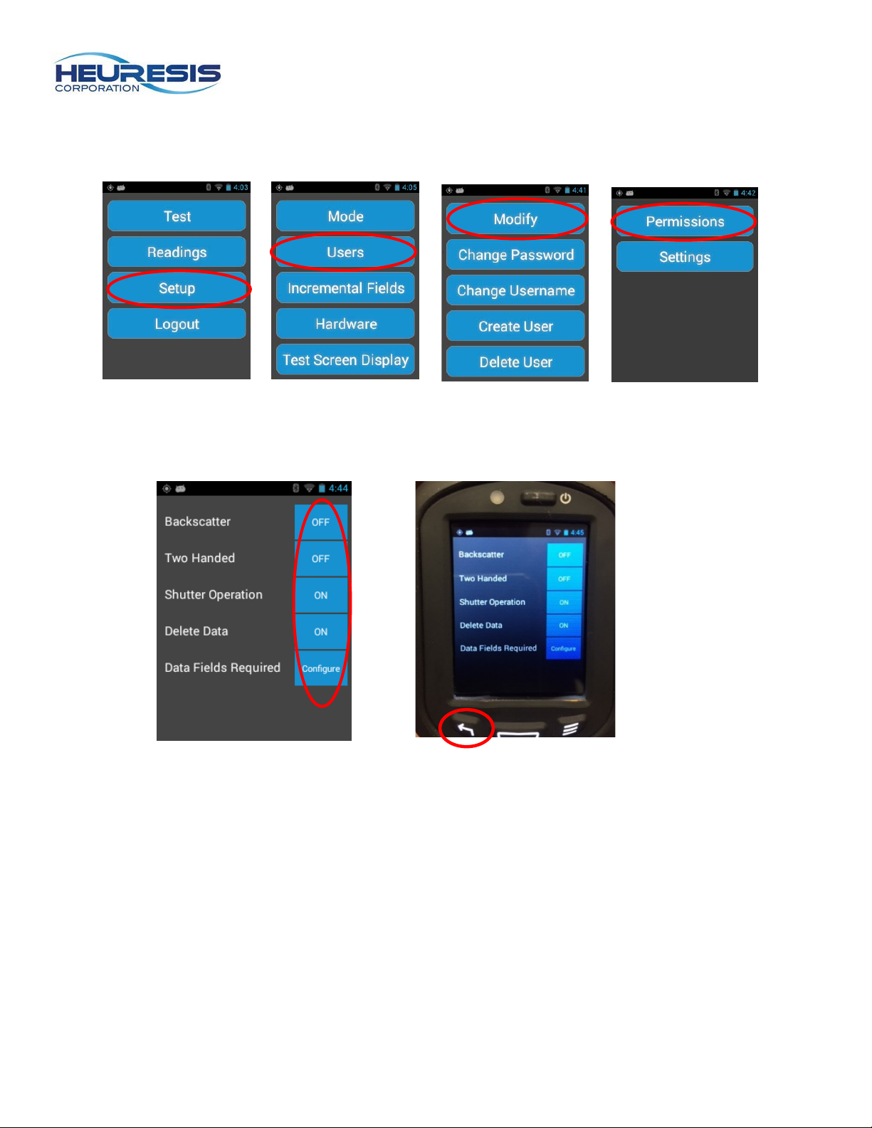
To view the rights of the administrator, return to the main menu. Select setup, followed by users, then modify and finally settings. (Figures 92 to 95)
As an administrator or Su p ervisor , you can turn ON/OFF any of the available options. To save, select the
back arrow on the analyzer and exit the menu (Fig. 96 and 97).
For more information on Permissions and Settings, please see Appendix A.
Page 31
Page 31
Figure 98
Figure 99
Figure 100
Figure 101
Figure 102
Changing passwords/user name
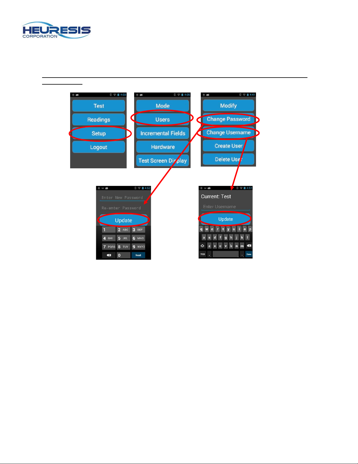
Follow these steps to change your password or user name. From the main menu select Setup>Users> Change Password (or Change Username) (Fig. 98 to 100). Select “Update.”
Caution: User names must be at least four characters long, and passwords must be at least six numbers long.
Page 32
Page 32
Figure 103
Figure 104
Figure 105
Figure 106
Figure 107
Creating a User/Supervisor
Creating another User or Superv is or ID on the Pb200i lets you easily identify who was using the
instrument for an inspection, and/or restrict certain functions of the instrument on a user-by-user basis to
reduce potential for error, such as a User accidentally deleting stored readings.
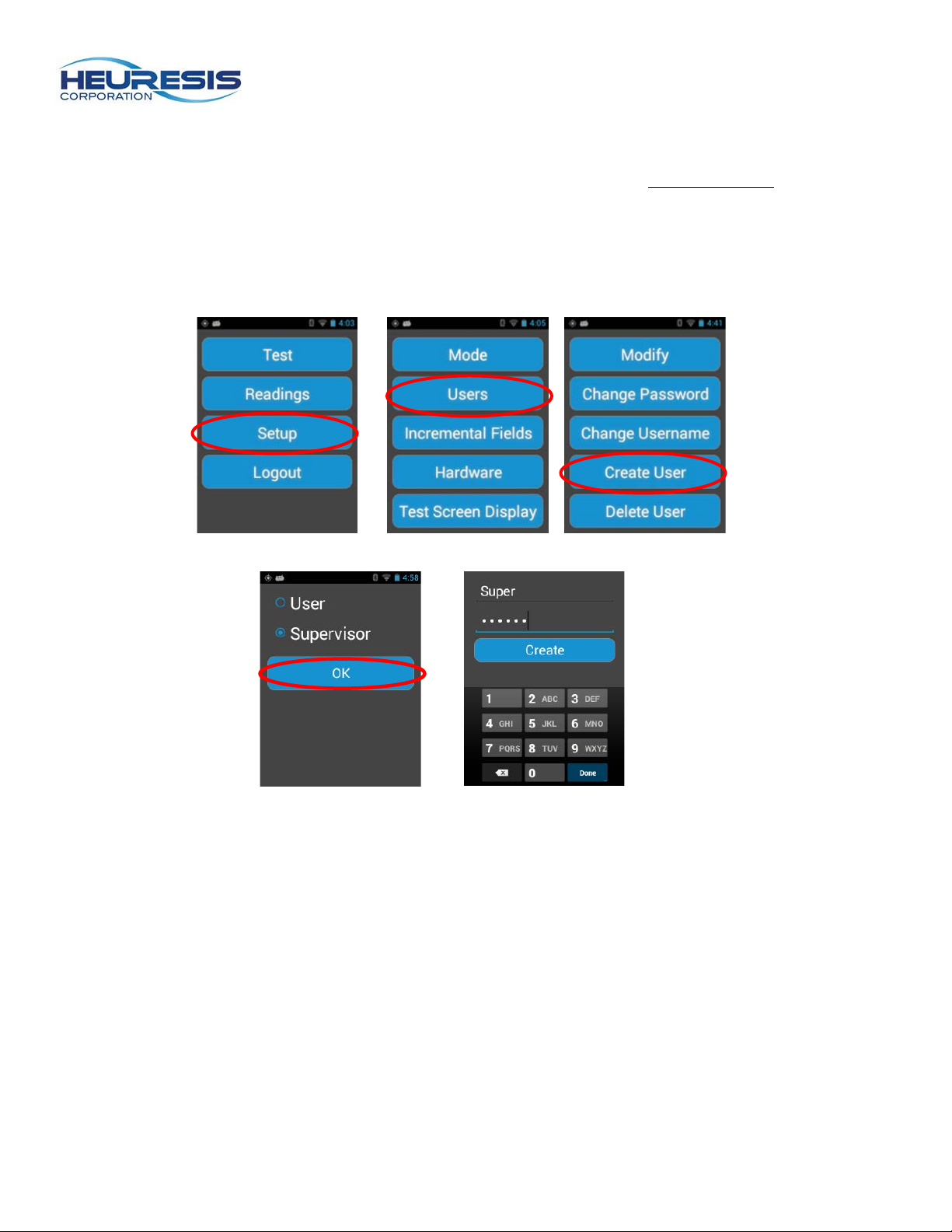
To create a Supervisor ID on the Pb200i, start at the Main Men u. Se lect Setup>Users>Create User.
Select “Supervisor” and create a new password (Fig. 103 to 107).
Caution: Only an administrator can set up these rights.
(Figures 64 to 68)
Page 33
Page 33
Figure 108
Figure 109
Figure 110
Figure 10
Figure 112
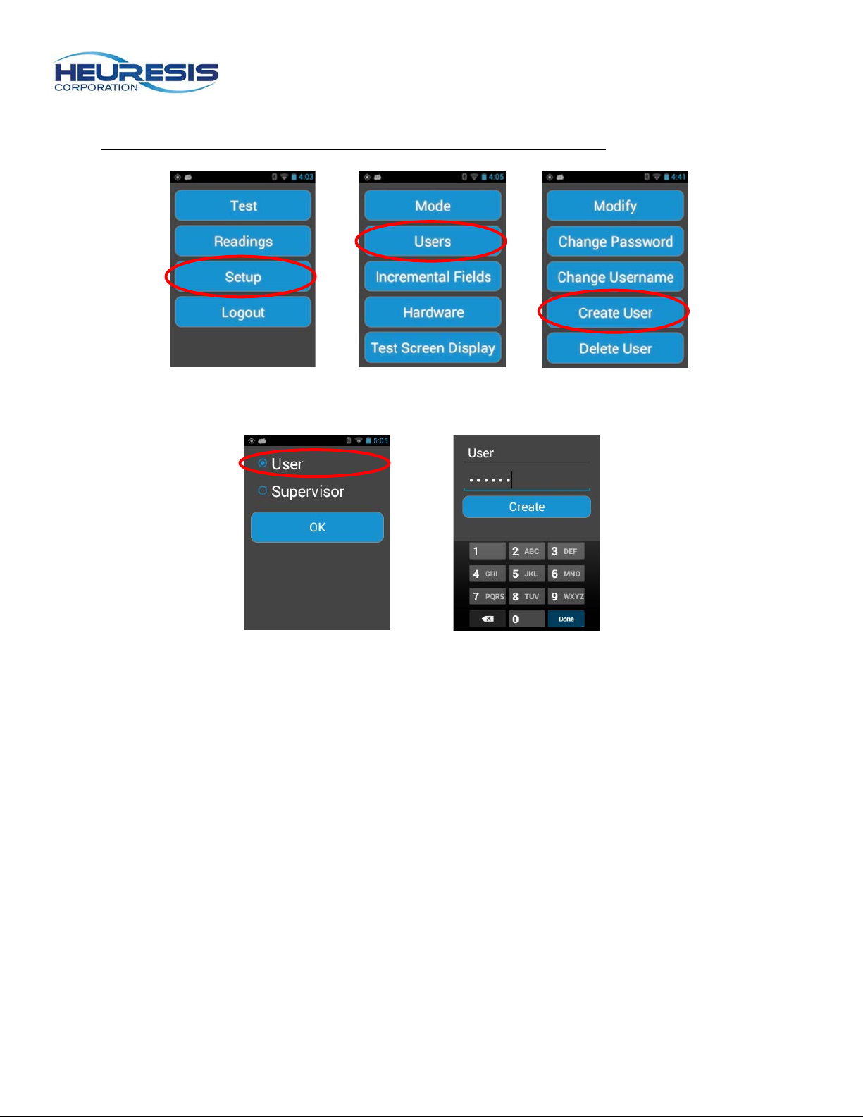
To create a user ID on the Pb200i, start at the main menu. Select Setup>Users>Create User. Select
“User” and create a new password.
Caution: Only an administrator can set up the se rig hts (Figures 108 to 112).
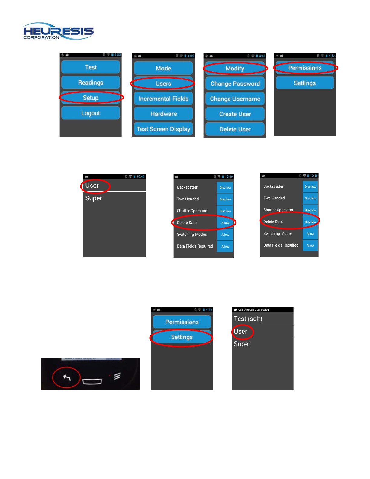
Modifying Permissions
An administrator can modify the permissions for themselves, a Supervisor, or a User. A Supervisor can
only modify the permissions for a User.
The example shown here illustrates the administrator revoking the default permission to delete data for a
user’s ID.
Start at the main menu. Select Setup> Users>Modify>Permissions. (Fig. 113 to 116) Select the user and
change “Allow” to “Disallow” (Fig. 117 to 119). The factory default settings are shown in Figure 118.
Page 34
Page 34
Figure 113
Figure 114
Figure 115
Figure 116
Figure 117
Figure 118
Figure 119
Figure 120
Figure 121
Figure 122
Back out using the Back button (Fig. 120) to save, then go to “Settings” and select “User” (Fig. 120 to
121).
Page 35
Page 35
Figure 123
Figure 124
Figure 125
Figure 126
Figure 127
Figure 128
Figure 129
Figure 130
Figure 131
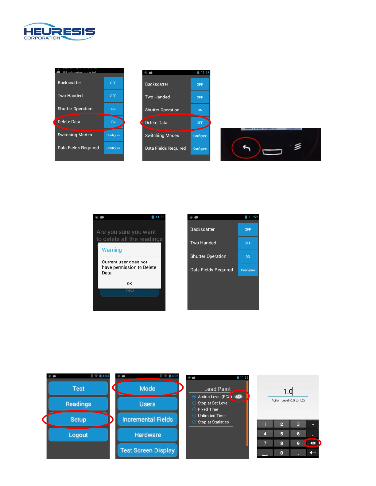
Turn the “Delete Data” toggle to the “OFF” position and back out with the Back button (Fig. 123 to 125).
In the example shown here, when the user logs in, if they try to delete data, they will see the error
message shown (Fig. 126). If they went to their settings, the choice to “Delete Data” is no longer available
(Fig. 127).
Changing the Action Level in Action Level Mode
In some instances, the user will want to change the action level to accommodate a Pb threshold other
than the default of 1.0 mg/cm
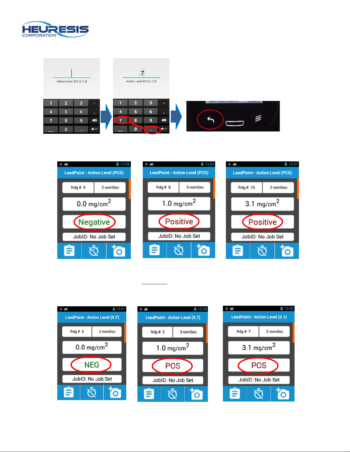
Setup>Mode>Action Level Mode , tap the gear icon and input the number (Fig. 128 to 133). Press the
Back button (Fig. 134).
2
. In order to change the action level, start at the main menu, select
Page 36
Page 36
Figure 132
Figure 133
Figure 134
Figure 135
Figure 136
Figure 137
Figure 138
Figure 139
Figure 110
When the action level is set to 1.0 mg/cm2, the instrument will display results as shown in Fig. 135 to 137.
When the action level is set to anything other than 1.0 m g/cm2, the instrument will display “NEG” (for
negative) and “POS” for positive. In this example, the action level has been set to .7 mg/cm2 (Fig. 99 to
101).
Figure 99 Figure 100 Figure 101
Page 37
Page 37
Figure 141
Figure 142
Figure 143
Extended Reading Mode
Extended reading mode is used for occupational inspection work where the quantification of lower levels
of lead may be required. This usually entails longer reading times for the instrument. Extended Reading
Mode is broken down into four “sub” modes for the user: Stop at Set Level, Fixed Time, Unlimited Time,
and Stop at Statistics.
Stop at Set Level
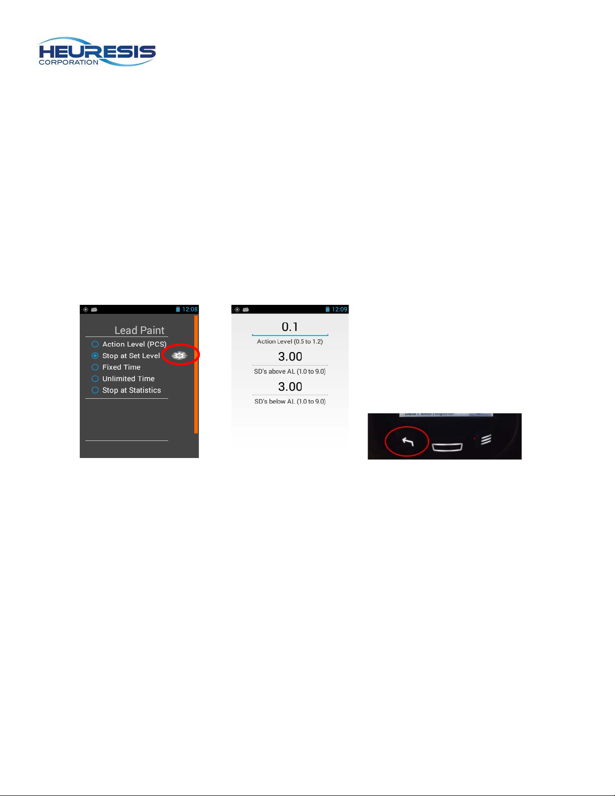
Stop at Set Level mode allows the user to set up the instrument with three variables: action level, number
of standard deviations above the action level, and number of standard deviations below the action level.
Once these user-determined thresholds have been reached, the instrument will stop acquiring data, close
the safety shutter, and display a result. This mode may be useful for customers performing commercial,
industrial, and/or institut ional Pb inspec t ion work, where they are looking for the Pb200i to terminate the
measurement once customer-determined statistical confindence has been achieved.
To setup this mode, start at the main menu. Select Setup>Mode>Stop at Set Level (Fig. 141), set the
action level, SD’s above, and SD’s below (Fig. 142), and select the Back button (Fig. 143).
Page 38
Page 38
Figure 144
Figure 145
Figure 146
Figure 147
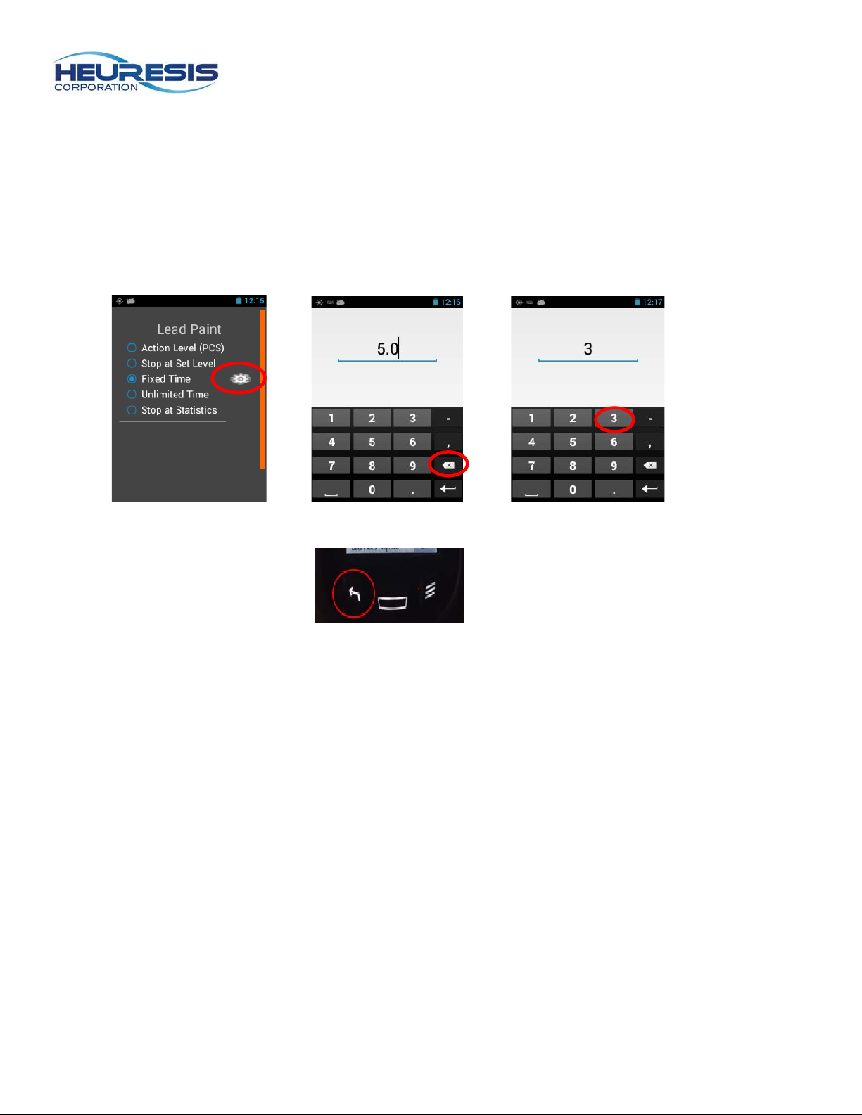
Fixed Time
Fixed Time mode allows the user to set a maximum time the instrument will take a reading with the trigger
depressed. Once the instrument reaches this set time, it will stop acquiring data, close the safety shutter,
and display a result. The value of time that can be entered is in real time seconds, up to a maximum of
300 seconds (5 minutes). This mode is often employed when users are following a strict standard
operating procedure (SOP) that prescribes the length of each reading that must be taken on a given
project.
To setup this mode, start at the main menu. Select Setup>Mode>Fixed Time. Enter the desired time limit
in seconds (Fig. 144 to 146), then select the Back button (Fig. 147).
Page 39
Page 39
Figure 148
Figure 129
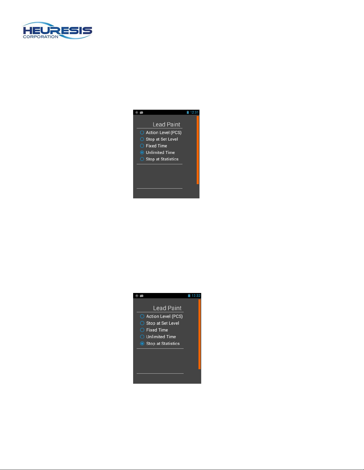
Unlimited Time
Unlimited Time mode allows the user to simply pull the trigger until they are satisfied with the result for a
given reading up to a maximum reading time of 300 nominal (source) seconds (5 minutes). Releasing the
trigger will prompt the instrument to close the safety shutter and display a result.
To setup the Unlimited Time mode, start at the main menu. Select Setup >Mode>Unlimited Time (Fig.
148). Select the Back button.
Stop at Statistics
Stop at Statistics mode automatically terminates the measurement when there is no statistical advantage
to sampling for additional time. This may be beneficial to customers looking for low levels of Pb in
commercial, industrial, and/or institutional insp ec tio n wor k.
To setup this mode, start at the Main Menu. Select Setup > Mode> Stop at Statistics (Fig. 149). Select
the Back button.
Page 40
Page 40
Figure 130
Figure 151
Figure 152
Figure 153
Figure 154
Additional Features
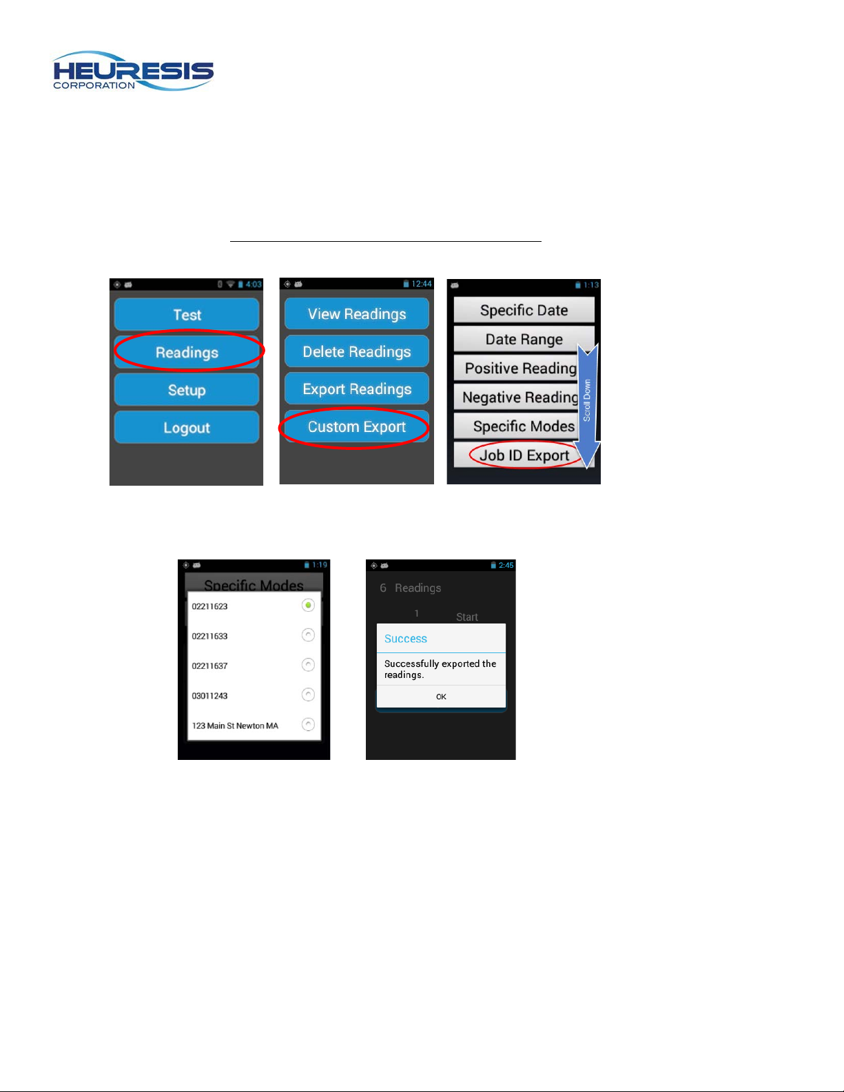
Custom Exporting
The Pb200i allows you to customize the content of exported CSV files. You may select any of the options
shown in Fig. 152 by following the prompts. Use of the JobID field permits you to export readings on a
job-by-job basis (see Creating a Job and Performing a Calibration Check for more information on using
the JobID field).
Page 41
Page 41
Figure 159
Swipe left or
test screen
Figure 155
Figure 156
Figure 157
Figure 158
Figure 160
Figure 141
Camera
The Pb200i’s built-in camera is located in the foot of the instrument (see Fig. 1). The camera is operated
using the Pb200i application on the instrument.
Caution: Do not use the android camera application that is on the analyzer.
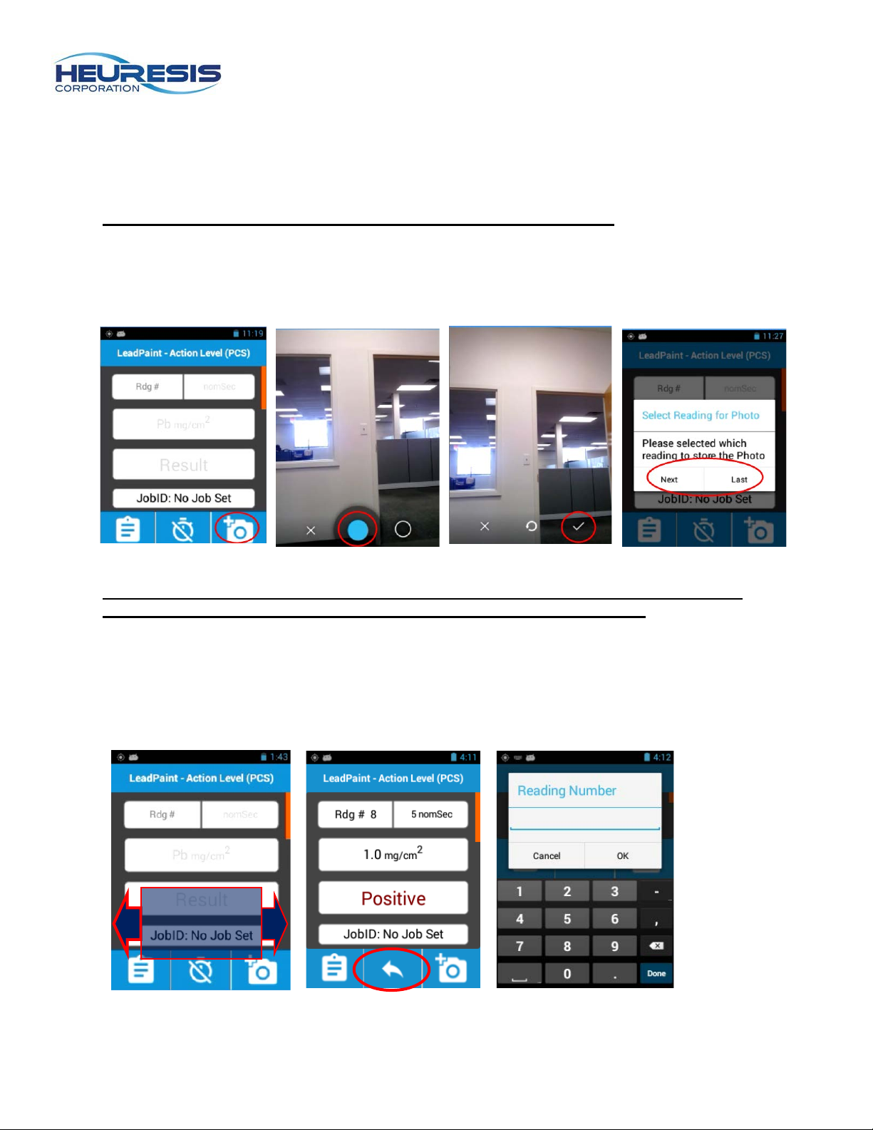
To use the camera, select the camera icon (Fig. 155). Select the blue dot (Fig. 156) to take the picture,
the “X” to exit the camera, or the white circle to adjust camera settings. Select the checkmark to store the
photo (Fig. 157), the circle with arrow to retake the photo, or the “X” to exit the camera. Once you have
stored the photo, select whether you want it associated with the next or the last XRF reading (Fig. 158).
Note: Please refer to the section on Exporting Readings and the HDMS User Guide for
more information on retrieving photos captured during your inspections.
Swipe to View Readings from Test Screen
You may swipe left or right from the "Ready to Test" screen to view readings (F ig. 159). You may also use
the search function to go to any desired reading (Fig. 160 and 161). Press the Back button on the
analyzer to return to the “Test” screen ( Fig. 133) .
right from
Page 42
Page 42
Figure 162
Figure 163
Figure 164
Figure 165
Figure 166
Test Screen Display Functionality
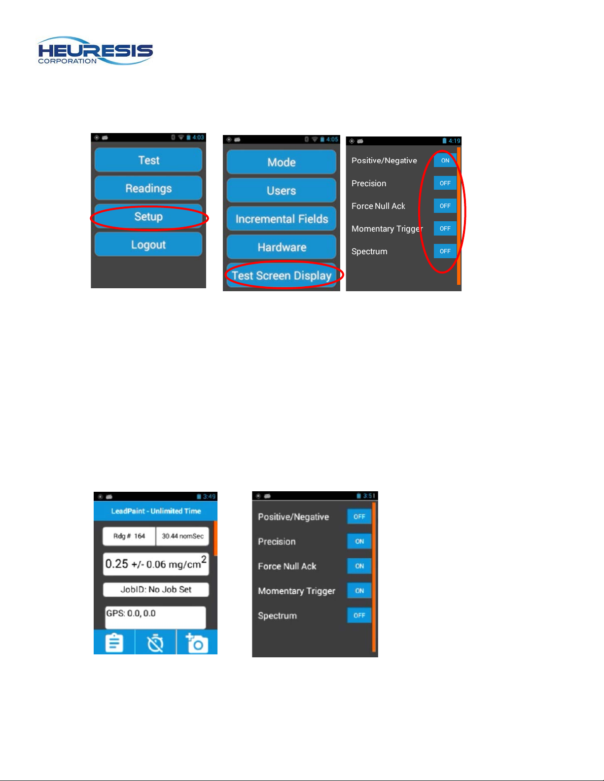
The user may tailor the test screen with any number of combinations, selectable by on/off toggles. From
the Main Menu, go to Setup>Test Screen Display (Fig. 162 to 163).
Individual settings are shown in Fig. 164. Positive/Negative permits you to turn off a Positive/Negative
result when compared to a threshold value of lead in paint. It may be useful to you to turn off
Positive/Negative for commercial/industrial lead inspection work, where one is typically looking for
accurate measurements for a lower level of lead. The factory default for this setting is “ON.”
Precision displays/hides the two-sigma (95% confidence). It is often turned “ON” in combination with
Positive/Negative “OFF”. The factory default for this setting is “OFF.” We don’t recommend turning it
“ON” in conjunction with Positive/Negative set to “ON” as Action Level mode already takes into account
the Pb200i’s two-sigma confidence as to whether the result is positive or negative when compared to an
2
action level of 1.0 mg/cm
.
An example of the Test Screen Display set for commercial/industrial lead inspection work, along with the
associated display settings are shown in Fig. 165 and 166.
Page 43

Page 43
Radiation Safety:
Every Heuresis Pb200i Lead Analyzer is des ig ne d to be saf e as possib le. As with an y device that
produces ionizing radiation, you should follow basic radiation protection precautions to ensure the
maximum safety for you and those around you.
The Heuresis Pb200i is approved for a 370 MB1 (10 mCi)
is supplied to customers with a 185 MBq (5 mCi) source. The radioactive material is contained in a sealed
capsule (referred to as a “sealed source capsule”). The capsule is fully contained by the shutter
mechanism and cannot be accidentally (or deliberately) removed from the device without disassembling
the instrument.
The sealed source capsule is located in the instrument’s snout. When the shutter is open, gamma rays
and x-rays from the source are emitted in the forward direction from the front of the device.
There are two controls that need to be activated before the shutter will open. First, the proximity sensor
at the front of the snout must be depressed. To do this, press the front of the instrument against the
surface to be measured. Second, the trigger on the handle must
the reading. Releasi ng the tr igger or lifting the snout of the instrument from the sample so that the
proximity sensor is not fully depressed will stop a reading in progress.
In a Action Level Mode where the measurement stops automatically, the shutter will automatically close
when the reading is complete.
Caution: The proximity switch must be pressed before the trigger is pressed, or the shutt er will not open.
The shutter of the device will automatically close when a reading is complete, even if you continue to ho ld
the instrument against the sample. The large majority of the instrument readings will take less than two
seconds.
The Pb200i is designed so you cannot accidently open the shutter. The instrument requires a password
to operate the shutter. Be sure to release the trigger before you remove the instrument from the surface
being tested. If you accidentally keep the trigger depressed when you lift the instrument, the shutter will
close automatically, as the proximity switch will not be activated.
The shutter should only be opened when the instrument is placed against the sample. Do not hold the
sample to be measured, or any body parts, in the path of the primary x-ray beam. When measuring a
surface such as a wall or door, make sure no one is located within 1m (approximately 36”) on the direct
opposite side of the surface being measured.
During testing, a strong beam of radiation (gamma-rays and x-rays) is continuously emitted through the
aluminum faceplate at the front of the Pb200i. Some radiation is produced at the top, sides, and bottom of
the snout of the instrument. There is also negligible radiation where your hand holds the instrument.
Warning: Always treat radiation with respect. Do not put your hand on the front end of the Pb200i
while taking a measurement. Never point the Pb200i at yourself or anyone else when the shutter is
open.
Caution: When testing the exterior of a window from the inside of a room, avoid standing in the
path of the Pb200i's radiation beam. The beam emits upwards from the front of the instrument.
57
Co sealed radioisotope; typically, the device
be pressed. Opening the shutter starts
Page 44

Page 44
Typical dose rates (5 milliCurie [185 MBq] source)
with the shutter closed,
in milliREM/hr.,
are as follows:
5 cm 30 cm 100 cm
Left 0.75 0.03 <0.01
Right 0.48 0.025 <0.01
Top 0.25 0.025 <0.01
Bottom 0.55 0.025 <0.01
Front 1.0 0.035 <0.01
Rear 0.05 0.015 <0.01
Typical dose rates (5 milliCuries [185 MBq] source)
with the shutter open,
taking a reading on wood,
in milliREM/hr.,
are as follows:
5 cm 30 cm 100 cm
Left 1.3 0.045 <0.01
Right 1.7 0.06 <0.01
Top 1.9 0.055 0.015
Bottom 0.70 0.04 <0.01
Rear 0.20 0.025 <0.01
Page 45

Page 45
Operating Conditions & Other Safety
Please follow these operating conditions when using the Heuresis Pb200i:
• Your organization’s radiation safety officer (RSO) should set up and assign the passwords for
users who are permitted to take measurements. Safety options for users can be mandated and
assigned by the RSO.
To take a reading with the Pb200i, the instrument must be held against a surface. [The shutter will not
open unless the proximity switch is activated. The shutter will close as soon as the Heuresis Pb200i is no
longer pressed against a surface. The shutter will close at the end of each reading.]
- The shutter should be open only during a measurement.
- The shutter should be open only when the instrument is in use, taking a measurement.
• Never point the Pb200i at yourself or anyone else when the shutter is open. Remember, the
radiation can penetrate doors, walls, etc. No one should stand within 1m (approximately 36”) of
the wall opposite the measurement location.
• The Heuresis Pb200i clearly indicates any time the shutter is open with red warning lights at the
top and sides of the instrument. Always observe the status of the warning lights.
• Always transport the device in accordance with the regulations of the jurisdiction in which you are
located. Always transport the device in the hard plastic case supplied with the instrument. This
case can be transported in a cardboard and foam over pack for additional protection. Be sure to
use all transportation labels required by the regulatory jurisdiction(s) wher e you are travel ling.
For more information consult the Heuresis DOT training presentation.
• Only those trained and authorized to use the Pb200i should operate the device. The Heuresis
Pb200i must be under the control of an authorized user and stored in an authorized and secure
location at all times.
• When removing the instrument from its storage location, it is critical to maintain a log of dates and
times removed and returned, location of use, and the name of the authorized user in possession
of the instrument. Include a comments section for noting any issues related to the instrument or
its use.
• The holster for the instrument contains shielding for emergency situations. If you suspect a
problem with the instrument, such as the shutter staying open, place the instrument firmly in its
holster. This ensures safe handling and protection against inadvertent exposure to radiation.
Page 46

Page 46
Radiation Dosimetry
Radiation dosimetry is worn to monitor radiation levels. It should be worn when required by your
regulatory jurisdiction, company safety policy, or RSO. Typically several rounds of dosimetry are used,
along with exposure time and use estimates to determine whether dosimetry should be discontinued. If
no dosimetry is used, a written justification must be kept on file.
Dosimetry can be obtained for companies such as:
Radiation Detection Company
3527 Snead Drive
Georgetown, TX 78626
Landauer Corporate Office
2 Science Road
Glenwood, IL 60425-1586
Dosimeters can be worn on a finger with a ring badge or on the body using a whole-body badge. Your
organization should have an established dosimetry program to determine the required use and type of
dosimeters. Always follow the instructions provided by the vendor when using dosimetry badges.
Dosimeters should be returned to the vendor for analysis.
Dosimetry badges are changed on either a monthly or quarterly basis. The correct option depends on the
dose received. If dosimetry is used, most users require a quarterly change – but this also depends on
whether the user is receiving a dose from another source.
Electronic dosimeters can also be used to electronically display the dose. Electronic devices are sold by
companies such as:
Canberra Industries, Inc.
800 Research Parkway
Meriden, CT 06450
Whatever method you select, be sure to maintain the proper records as mandated by your local
regulatory agency. Be sure to check for the time required in your juristiction. Some regulators require that
records are kept until the license is terminated, and then transferred to the regulatory agency.
Page 47

Page 47
Leak Testing
A leak test must be performed at least every 12 months on the Heuresis Pb200i, as specified in the
Registry of Radioactive Sealed Sources and Devices, Safety Evaluation of Device, No: MA-1397-D-101B. Certain regulatory jurisdictions, especially States requiring a Specific License, may require leak tests
every six months.
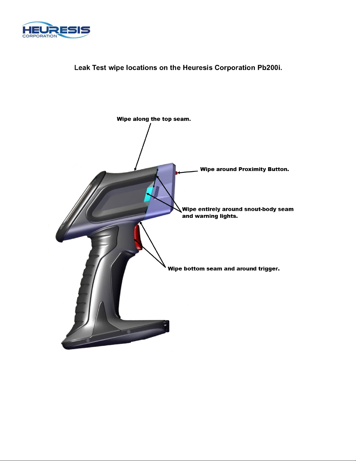
The leak test kit is provided by the laboratory that performs the leak test analysis. A leak test involves
wiping the seams of the front of the instrument to assess whether radioactive material has leaked from
the sealed source (extremely unlikely) and contaminated the outside of the instrument (Figure 111)
State radiation control programs maintain lists of approved leak test laboratories.
Two options include:
Valley Safety Services Associates
330 Old Enfield Rd.
Belchertown, MA 01007
Troxler Electronic Laboratories, Inc.
3008 Cornwallis Road
P.O. Box 12057
Research Triangle Park, NC 27709
A copy of the leak test results must be kept on file at your primary location of storage. It is also useful to
keep a copy of the leak test results with the instrument, as this may be required or desired in certain
transport situations. Heuresis recommends keeping a copy of the leak test results inside the instrument
transport case at all times.
It is important to maintain all leak test reports, even after expiration. Regulations vary on how long test
results should be maintained, but Heuresis recommends keeping leak test results for a minimum of two
years. Be sure to check your regulations to ensure compliance.
If the leak test expires on an instrument, the device must be taken out of use and placed in its secure
storage location. The instrument must be clearly marked as unusable until a valid leak test is conducted.
The instrument must have a valid leak test for transportation.
Conducting the Leak Test
Following the instructions of the leak test kit, wipe the areas shown in Fig. 137.
Page 48
Page 48
Figure 167
Page 49

Page 49
Emergency Procedures
CAUTION: This page contains important information that should be available to the Pb200i user AT ALL
TIMES.
Lost or Stolen Instrument
If this instrument is lost or stolen, notify your Radiation Safety Officer (RSO) or the equivalent responsible
individual at your organization. The RSO must notify the local radiation regulatory authority and the local
police. In addition, please notify Heuresis of the loss.
Damaged Instrument
Minor damage:
If the instrument is intact but the case is cracked, the shutter mechanism has failed, or the warning lights
stay lit when the shutter should be closed, do the following:
1. Place the instrument securely in its protective shielded holster. This should eliminate any external
hazard from radiation.
2. Place the instrument and holster securely in the instrument’s carrying case.
3. Notify your organization’s RSO.
4. Contact Heuresis for help and instructions.
Major damage:
If the instrument is not intact (i.e., the snout of the instrument is broken open, crushed, melted, etc.), do
the following:
1. Do not touch or move the instrument.
2. Establish a 10’ (2m) control area around the damaged instrument.
3. Do not leave the area unattended.
4. Approach the instrument only with a radiation survey meter capable of measuring in the millirem
range. Make sure you have proper training to perform this operation.
5. Contact your organization’s RSO or equivalent individual.
6. Contact hazardous materials response operations in your area for assistance, if required.
7. Regulations vary by state, each branch of the military, and on property under exclusive federal
jurisdiction.
8. Contact the local radiation regulatory authority and the local police.
9. Contact Heuresis immediately for help and instructions.
10. Conduct a contamination survey in the event of major damage.
Caution: A broken instrument does not necessarily indicate radioactive contamination from the event.
While there may be radiation emitting from the instrument, the radioactive material may still be sealed in
the source capsule.
Page 50

Page 50
Emergency Numbers
Please fill out the following fields in case of emergency:
Regulatory authorit y____________________ ___ ___ _ ____ ___ ___ __ __________
Your organization’s RSO _____ ___ ___ ________________ ___ ___ __ ___ ___ ___ _
Additional company contact(s)____________________________________
Storage location______ ___ ____ ___ ___ __ ___ _________________ __ ___ __
City police____________________________________________________
State police________________________________________________________
Fire department________________________________________
Heuresis emergency contact: Ken Martin 1-617-751-8286 (call or message any time)
You should also know the contact information for the police and fire departments where you are using the
instrument.
Police____________________________
Fire____________________________
Other contacts:
_____________________________________ __________________________
_____________________________________ __________________________
Your organization contact information (in case the Pb200i is lost and somebody finds it and is trying to
return it to you):
Caution: these contacts should be kept on the operator’s person and with the instrument.
If you encounter any issues or have questions related to the safe operation of the device, call the
Heuresis Radiation Safety Officer, Ken Martin, 1-617-751-8286 or email [email protected]
.
Page 51

Page 51
Warranty
Seller warrants that the Products will operate or perform substantially in conformance with Seller's published
specifications and be free from defects in material and workmanship, when subjected to normal, proper and
intended usage by properly trained personnel, for the period of time set forth in the product documentation,
published specifications or package inserts. If a period of time is not specified in Seller’s product
documentation, published specifications or package inserts, the warranty period shall be one (1) year from the
date of shipment to Buyer in the country of purchase. Any part replaced on an instrument, covered by the
original factory warranty, will be warranted for the remainder of the instrument’s factory warranty. Seller agrees
during the Warranty Period, to repair or replace, at Seller's option, defective Products so as to cause the same
to operate in substantial conformance with said published specifications; provided that Buyer shall (a) promptly
notify Seller in writing upon the discovery of any defect, which notice shall include the product model and serial
number (if applicable) and details of the warranty claim; and (b) after Seller’s review, Seller will provide Buyer
with service data and/or a Return Material Authorization (“RMA”), which may include biohazard or other
Radiation safety decontamination procedures and other product-specific handling instructions, then, if
applicable, Buyer may return the defective Products to Seller with all costs prepaid by Buyer. Replacement
parts may be new or refurbished, at the election of Seller, the warranty of these parts expire with the instrument
warranty. All replaced parts shall become the property of Seller. Shipment to Buyer of repaired or replacement
Products shall be made in accordance with the Delivery provisions of the Seller’s Terms and Conditions of
Sale. Accessories and Consumables are expressly excluded from this warranty.
Notwithstanding the foregoing, Products supplied by Seller that are obtained by Seller from an original
manufacturer or third party supplier are not warranted by Seller, but Seller agrees to assign to Buyer any
warranty rights in such Product that Seller may have from the original manufacturer or third party supplier, to
the extent such assignment is allowed by such original manufacturer or third party supplier.
In no event shall Seller have any obligation to make repairs, replacements or corrections required, in whole or
in part, as the result of (i) normal wear and tear, (ii) accident, disaster or event of force majeure, (iii) misuse,
fault or negligence of or by Buyer, (iv) use of the Products in a manner for which they were not designed, (v)
causes external to the Products such as, but not limited to, power failure or electrical power surges, (vi)
improper storage and handling of the Products, (vii) use of the Products in combination with equipment or
software not supplied by Seller, (viii) Moderately heavy or excessive impact against any object, including but
not limited to floors, walls, furniture, sample or other objects, (ix) Excessive water, moisture or condensing
humidity that breaches the instrument seals, (x) Excessive or extreme ambient or direct temperature or (xi)
Heavy vibrations directly to the instrument for extended periods of time. If Seller determines that Products for
which Buyer has requested warranty services are not covered by the warranty hereunder, Buyer shall pay or
reimburse Seller for all costs of investigating and responding to such request at Seller's then prevailing time
and materials rates. If Seller provides repair services or replacement parts that are not covered by this
warranty, Buyer shall pay Seller therefore at Seller's then prevailing time and materials rates.
ANY INSTALLATION, MAINTENANCE, REPAIR, SERVICE, RELOCATION OR ALTERATION TO OR OF, OR
OTHER TAMPERING WITH, THE PRODUCTS PERFORMED BY ANY PERSON OR ENTITY OTHER THAN
SELLER WITHOUT SELLER'S PRIOR WRITTEN APPROVAL, OR ANY USE OF REPLACEMENT PARTS
NOT SUPPLIED BY SELLER, SHALL IMMEDIATELY VOID AND CANCEL ALL WARRANTIES WITH
RESPECT TO THE AFFECTED PRODUCTS.
THE OBLIGATIONS CREATED BY THIS WARRANTY STATEMENT TO REPAIR OR REPLACE A
DEFECTIVE PRODUCT SHALL BE THE SOLE REMEDY OF BUYER IN THE EVENT OF A DEFECTIVE
PRODUCT. EXCEPT AS EXPRESSLY PROVIDED IN THIS WARRANTY STATEMENT, SELLER
DISCLAIMS ALL OTHER WARRANTIES, WHETHER EXPRESS OR IMPLIED, ORAL OR WRITTEN, WITH
RESPECT TO THE PRODUCTS AND INCLUDING WITHOUT LIMITATION ALL IMPLIED WARRANTIES OF
MERCHANTABILITY OR FITNESS FOR ANY PARTICULAR PURPOSE. SELLER DOES NOT WARRANT
THAT THE PRODUCTS ARE ERROR-FREE OR WILL ACCOMPLISH ANY PARTICULAR RESULT.
Specific warranties of common accessories:
Battery charger and battery packs are warrantied for twelve (12) months
Standard instrument accessories are warrantied for twelve (12) months
Parts or spare parts sold, installed or supplied outside of the product warranty period are warrantied for
twelve (6) months
Page 52

Page 52
Appendix A
Permissions and Settings
The Permissions and Settings on the Pbi200 are used to allow users the ability to use and set the
functions on the instrument.
Permissions are given to the User by an Administrator or a Supervisor for various functions. These
functions are those that control certain radiation safety features (such as shutter operation) or the
handling of data (such as the ability to erase data).
Settings on the Pb200i can be set by the User, Supervisor, or Administrator. Certain settings require
permission from the Administrator or the Supervisor to change.
Use of Permissions and Settings
• The permissions are controlled by the Administrator and/or the Supervisor. The is accomplished
through the Password system.
• In the most basic configuration, the Administrator (set up in the initial use of the instrument) would
configure a User and set the Permissions for that User. The Administrator can also set up the
initial settings on the instrument. This allows each user to have the initial settings be consistent
with all users. Unless restricted by permissions set by the Administrator, the User can change
the settings.
• A less basic configuration allows the Administrator to add a Supervisor level above the User. The
Supervisor can set permissions for the User. In this configuration, the Supervisor permissions
override the Administrator permissions.
• The User cannot change permissions. The User can change settings that are not restricted by
the permissions given. The exception to this is that the User can always change a setting to a
more restrictive option for the setting. For example, if a User is not given permission to delete
data then they cannot change that setting. If, however, they are given permission to delete data,
they can change the setting so that they cannot delete data (and change it back from there).
All permissions and settings are saved and continue with the next use of the instrument, for that User.
 Loading...